Table of Contents
Advertisement
Advertisement
Table of Contents

Related Manuals for Bang & Olufsen BeoVision 4-85


Summary of Contents for Bang & Olufsen BeoVision 4-85
- Page 1 BeoVision 4-85 Installationguide for BeoVision 4-85, Floor Stand Version 1.1...
-
Page 2: Contents Introduction
- Precautions - Assembly and installation of Floor Stand - Mechanical specifications for BeoVision 4-85, Floor Stand. Important ! Since both the plasma panel and the stand are sizeable dimensions, it is strongly recommended to read the warning and precautions section carefully. -
Page 3: Warning / Precautions
Edges of the items The shape of BeoVision 4-85 and the floor stand may be considered as potential risks when they are free hanging items. Be aware of their positions when they are free hanging in the active working area during the installation, to avoid getting injured. -
Page 4: Installation Overview
Installation overview Installation overview Introduction Apart from the Floor Stand, the basic set-up of BeoVision 4-85 includes the following items: Warning/Precautions - BeoVision 4-85 PDP (Plasma Display Panel) incl. IR, ACM and shielding frames - BeoSystem 3 - BeoLab 10... - Page 5 Hw = ≤ 18 cm (height of wheels) The weight of BeoVision 4-85 is approx. 145 kg and approx. 260 kg for the Floor Stand. It is recommended to use a crane which is approved to handle loads up to 350 kg at L = 135 cm for Floor Stand installations (155 cm for wall bracket installations).
-
Page 6: Installation, Floor Stand
Installation, Floor Stand Installation, Floor Stand The elements in the Floor Stand installation consists of Floor Stand assembly ( ➀ ) and TV placement ( ➁ ➀ To ensure a smooth installation it is recommended to follow a structured procedure. Please follow the suggested procedure below: - Place the Floor Stand in its packaging. -
Page 7: Removal Of Floor Stand Packaging
Installation, Floor Stand Removal of Floor Stand packaging When the product is placed in its packaging the next step is to remove the packaging parts. Follow the procedure below: >>> > Unlock all clips in the packaging as shown and >... -
Page 8: Assembly Of Floor Stand
Installation, Floor Stand >>> > Place the floor stand plate on the top of the two bars as shown. Assure that the assembly area under the fortification points for the legs is sufficient. > Fasten the frame of the floor stand to the crane with a suitable lashing belt. -
Page 9: Placement Of Floor Stand
Installation, Floor Stand > Before the Floor Stand placement is completed, connect the wire safely from the stand plate to the wire from the stand leg (shown here). Pull gently at the wire on the top of the tube before lowering the stand legs. >... -
Page 10: Alignment Of Stand Feets / Removal Of Safety Bolts
Installation, Floor Stand Alignment of stand feets > Adjust the eight feet under the stand plate to align the level of the floor. Make sure that all of the eight feet are in contact with the floor. It is very important that this alignment is performed correctly. Otherwise the stability will not be sufficient for the tilt and turn functions. -
Page 11: Installation, Tv
Placement of TV in packaging The purpose of this step is to place the BeoVision 4-85 in its packaging in an appropriate place. The aim is to obtain as less movement of the TV as possible, which is a great advantage when moving large objects. -
Page 12: Removal Of Tv Packaging
Installation, TV Removal of TV packaging When the product is placed in its packaging the next step is to remove the packaging parts. Follow the procedure below: > Remove the securing belts > Remove the top packaging > Remove the front packaging >... -
Page 13: Removal Of Tv From Packaging
Installation, TV Removal of TV from packaging The TV is now free-standing and ready for transport. When the TV is removed and free from the packaging the plates and the EMC gaskets must be installed. Follow the procedure below (depending of the crane type the procedure may vary): >... -
Page 14: Replacing Stand Hooks On Tv
Installation, TV Replacing stand hooks on TV The next step is to remove the stand hooks (as delivered from factory). This is necessary to be able to attach the TV to the Floor Stand. Follow the procedure below: (x2) (x2) (x2) 14 mm 10 mm... -
Page 15: Installing The Tv On The Floor Stand
Installing the TV on the Floor Stand Installing the TV on the Floor Stand The TV is now ready to be installed on the Floor Stand. Move the crane with the TV to the Floor Stand. > Move the position of the TV and align to fit the four eyebolts to the mounting holes on the Floor Stand (see below). ! It is recommended to have at least one person steering the crane and two persons steering the TV to prevent damaging the product. -
Page 16: Installing Shielding Frames
Installing shielding frames Installing shielding frames Install the four shielding frames (MDF supplied with the TV) in the following order: Shielding frame >>> ! It is important that tongued and grooved fits perfectly. > Shielding frame top. > Shielding frame bottom. Screws Shielding frame >>>... -
Page 17: Connection Of Cables To The Tv
Connection of cables to the TV / Horizontal TV adjustment Connection of cables to the TV Connect the cables from the cable chain to the connectors on the TV: Control/Camera module: > HDMI cable - to BS3 > RS232 cable - to BS3 >... -
Page 18: Assembly Of Cabinet Parts
Assembly of cabinet parts Assembly of cabinet parts Survey of mounted back covers: Cabinet 1 (TV) Cabinet 2 (Stand) Cabinet 3 (Speaker) Mains inlet Safety bolt / Safety bolt / inspection hatches inspection hatches Cabinet 3 ➁ ➁ ➀ >>> Left Right >... - Page 19 Assembly of cabinet parts Cabinet 2 > Lead the cable bundle (from the Floor Stand and the TV) through the cable hole in the Stand cabinet. Eccentric screw > Turn the eccentric adjustment screw clock-/counterclockwise to move the position of the knob in horizontal/vertical direction. The aim is to obtain that ‘A’...
-
Page 20: Connection Of Beovision 4-85 / Beosystem 3
For installation on the Japanese market see page > Connect the two mains cables from the stand to the mains (wall plug) and switch on BeoVision 4-85 by pressing TV (await the product to start up). Disconnect the product from the mains The next step is to attach BeoLab 10 to the speaker bracket. -
Page 21: Installing Beolab 10
Installing BeoLab 10 Installing BeoLab 10 Mount the center speaker (BeoLab 10) to the Floor Stand. 5mm (x4) > Mount the speaker bracket for BeoLab 10 onto the speaker plate on the > Mount the Power Link cable and the mains cable from the Floor Stand the four supplied screws ‘... -
Page 22: Setting-Up Pdp Settings
- Locate the label on the back side of the TV and write down the printed values: Bsys3 Enter values in to Panel/PW adjust menu WPR = - Switch on BeoVision 4-85 by pressing TV and await the product to WPG = WPB = start up. BRIOF CONOF65= RCT = GCT = - Enter Service Menu by pressing: MENU 00 GO/OK. -
Page 23: Installation On The Japanese Market
Installation on the Japanese market Installation on the Japanese market On the Japanese market, it is necessary to increase the mains voltage from 200 volt to 220 volt. This is done to ensure sufficient voltage to the Actuator Control Unit. Installation overview Schematic diagram for transformer Autotransformer... -
Page 24: Technical Specifications
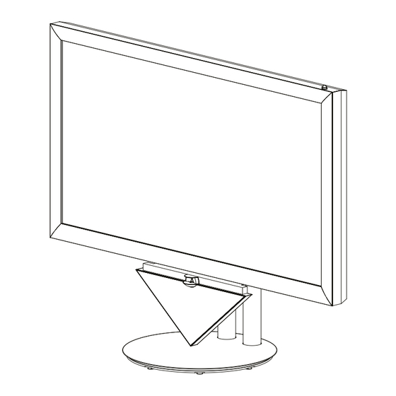
Technical specifications Technical specifications Size Weight (H x W x D) Item Item size Packing size Item Item weight Packaging weight Total weight Monitor 124.4 + 3.2 (IR eye) x 205.2 x 12.1 cm 153.5 x 223.5 x 80 cm Monitor 144 kg 89 kg... - Page 25 Technical specifications Outer dimensions Product view Front view...
- Page 26 Technical specifications Back view Left side view...
- Page 27 Technical specifications Top view Rotation view...
-
Page 28: Table Of Contents
Connection of BeoVision 4-85 / BeoSystem 3 Assembly of cabinet parts .............. 18 Connection of BeoVision 4-85 / BeoSystem 3 ....... 20 Installing BeoLab 10 Connect the product to the mains ..........20 Disconnect the product from the mains ........20 Setting-up PDP settings Installing BeoLab 10 ...............
Need help?
Do you have a question about the BeoVision 4-85 and is the answer not in the manual?
Questions and answers