Table of Contents
Advertisement
Quick Links
Advertisement
Table of Contents

Related Manuals for iLive ILBV94+1


Summary of Contents for iLive ILBV94+1
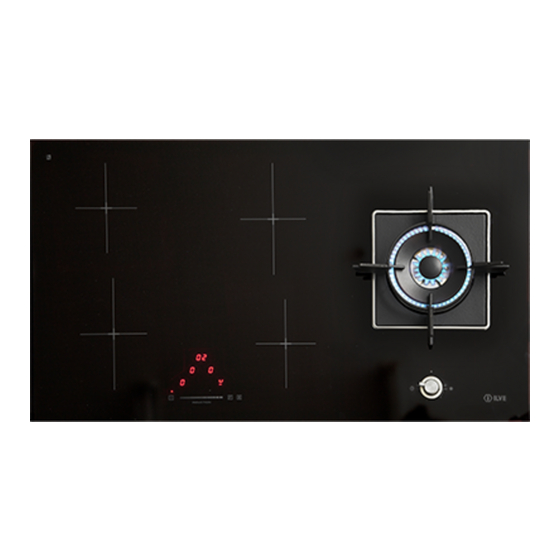
- Page 1 INSTRUCTION MANUAL GAS/INDUCTION COOKTOPS MODELS ILBV94+1 and ILWV94+1...
- Page 2 OPEN 24 ILVE ACCESSORIES ONLINE SHOP...
- Page 3 Dear customer, We thank you and congratulate you on your For service and spare parts, please choice. call the relevant number listed on This carefully designed product, the back page of this manual. manufactured with the highest quality materials, has been carefully tested to satisfy all your cooking demands.
-
Page 4: Installation
User instructions Installation All the operations concerned with the installation (electrical and gas connections, adaptation to type of gas, necessary adjustments, etc.) must be carried out by qualified technicians, in terms with the standards in force. For specific instructions, kindly read the part reserved for the installation technician. - Page 5 Important On floors with thermoelectric protection do not keep the ignite button pushed for more than 15 seconds. If the burner has not ignited after 15 seconds, open the door of the room and wait at least one minute before making a further attempt. Warning: If the surface is cracked, switch off the appliance to avoid the possibility of Ø...
- Page 6 Induction Heating by induction is the most efficient form of cooking available. The heat is generated by an electromagnetic field, directly on the bottom of the pan or pot used. The surface which is free from contact remains virtually cold. When the cooking time is up and the container is removed, there is no residual heat.
-
Page 7: Operating Principle
Operating principle This is based on the electromagnetic properties of most cooking containers. The electronic circuit governs the operation of the coil (inductor), creating a magnetic field. The heat is transmitted by the container to the food. Te cooking process takes place as follows: - minimum dispersion (high performance);... -
Page 8: Pan Detection
First of all, position the pan in the chosen cooking area. The absence of the pan display means the system cannot start. Pan detection A certainty which distinguishes the knowledgeable use of technology in favour of the consumer. After use, switch off the hob element by its control and do not rely on the pan detector. Danger of fire: Do not store items on the cooking surface CAUTION: The cooking process has to be supervised. - Page 9 1 ON/OFF 7B Display Timer 2 + Slider Area 8 Pause indicator light 3 - Slider Area 9 Timer indicator lights 4 Power Booster (P) 10 Cooking area decimal point...
- Page 10 “H” instead of “=”. The lower right corner of all cooking point displays flash at one-second intervals to indicate that no cooking areas has been selected at the time. After switching ON the electric control remains activated for 20 seconds. If no cooking zone or timer selection follows within this period of time, the electronic control automatically switches back into the stand-by mode.
- Page 11 Wattage settings The output of the cooking zones can be set in 9 steps which are indicated by figures “1” to “9” by means of seven-segment LED displays. touch control heat intensity weak gentle slow medium strong bright A: INDUCTION COOKING ZONE ø160 LEVEL 9 = 1400W ABOUT MINIMUM START THRESHOLD 700W B: INDUCTION COOKING ZONE ø200 LEVEL 9 = 2300 W ABOUT MINIMUM START THRESHOLD 1200W...
- Page 12 Automatic heat-up function When the automatic heat-up function is activated the wattage of the cooking zone is at 100% for a certain heat-up time which is dependent on the setting selected (continuous). At the end of the heat-up time the electronic control switches back to the preselected simmering setting.
- Page 13 • The ON/OFF time of the relays • After switching OFF the cooking zone the respective display shows “H” until the assigned cooling zone temperature is mathematically in an uncritical level. (< 60°C). Automatic switch-off (limited operating time) Maximum operating time is defined for each hob zone. The maximum operating time depends on the selected cooking level (see table).
- Page 14 Unlocking for cooking The front right hob zone display (FR) and the special Power Booster (P) must be simultaneously pressed to unlock and prepare the Touch Control unit. The symbol [L] indicating LOCKED disappears from the display. The displays of all the hob zones display [0], together with a flashing dot.
- Page 15 Setting a timer value – Adjustment by means of the slider area. – The adjustment of the first digit usually occurs first, followed by the adjustment of the second digit. – Within 10 seconds after setting the second digit, the value might reset (the dot on the timer display and when there is a specific timer for a hob zone the assigned LED flashing).
- Page 16 Programming of the specific hob zone timer The power-on of the Touch Control enables the timer setting for dedicated hob zones. – If you activate a cooking area (cooking area level > 0) and then select the timer display (within 10 seconds), you can assign a value of the timer to the cooking area as a function of switching off the cooking area.
- Page 17 switches off after 2 hours). PAUSE Activation of the pause function When at least one hob zone is functioning, the heating elements can be deactivated by pressing the Pause key. The pause display has priority. The timers that have already been programmed (also for the independent timer) are stopped and do not function during the pause time.
-
Page 18: Maintenance
during the 3 seconds delay time of reduced power. Note: If there is even a slight crack in the cooking surface, immediately disconnect the power. Maintenance First of all remove stray food bits and grease drops from the cooking surface with the special scraper. -
Page 19: Installation Instructions
Installation instructions Installation This appliance shall be installed only by authorised persons and in accordance with the manufacturer's installation instructions, local gas fitting regulations, municipal building codes, electrical wiring regulations, AS/NZS 5601 - Gas Installations and any other statutory regulations. These instructions are aimed at qualified fitters as a guide to installation, adjustment and maintenance in compliance with the laws and standards in force. - Page 20 POSITION OF SEALANT IN THE POSIZIONE GUARNIZIONE SIGILLANTE SEMIFILOTOP VERSION NELLA VERSIONE SEMIFILOTOP Fig. 10...
- Page 21 Gas connection (Fig. 11) Connect the appliance to the gas cylinder or to the installation according to the prescribed standards in force, and ensure beforehand, that the appliance matches the type of gas available. Other wise, see ”Adaptation to various types of gas”. Further more, check that the feed pressure fall swithin the values described on the table: ”User chacteristics”.
-
Page 22: Electrical Connection
Fig. 13 Before Leaving Check all connections for gas leaks with soap and water. DO NOT use a naked flame for detecting leaks. Ignite the burner to ensure correct operation of gas valve, burner and ignition. Turn gas tap to low flame position and observe stability of the flame. When satisfied with the hotplate, please instruct the user on the correct method of operation. - Page 23 50 MIN. aria - air - air - Luft - aire - lucht - ar induzione - induction - induction - Induktion 100 cm MIN. - inducción - inductie - indução ZONA FORNO O ARMADIETTO OVEN ZONE OR CUPBOARD ZONE FOUR OU PLACARD OFENBEREICH ODER SCHRANK ZONA HORNO O ARMARIO OVENRUIMTE OF KASTJE...
- Page 24 Error code description Possible causes Error recovery The cooking zone can It’s not an error, the user A suitably pan must be be configured if a static is in the serivice menu. placed on the relevant “C” is shown. cooking zone. The cooking zone will be The user is in the Wait for the sysmbol...
- Page 25 Error code description Possible causes Error recovery Unsuitable pot, e.g. Pot creates on the 1. the error is lost of the magnetic module an improper automaticly cancelled characteristics because operating point which after 8s and the cooking of temperature in the can destroy devices, zone can be used bottom.
- Page 26 EUROLINX LIMITED WARRANTY Eurolinx Pty Limited A.B.N. 50 001 473 347 (a) damage through misuse (including failure to Office: 48-50 Moore Street, Leichhardt N.S.W 2040 maintain, service or use with proper care), neglect, Post: Locked Bag 3000, Annandale, N.S.W 2038 accident or ordinary wear and tear (including P: 1300 694 583 deterioration of parts and accessories and glass...
- Page 27 EUROLINX LIMITED WARRANTY 6. Claiming under the Warranty You are entitled to a replacement or refund for a major Customers will bear the cost of claiming under this failure and for compensation for any other reasonably Warranty unless Eurolinx determines the expenses are foreseeable loss or damage.
Need help?
Do you have a question about the ILBV94+1 and is the answer not in the manual?
Questions and answers