
Related Manuals for Bolton Tools BT1324


Summary of Contents for Bolton Tools BT1324
- Page 1 OWNER’S MANUAL MODEL:BT1324&BT1330 PRECISION METAL LATHE ASSEMBLY AND OPERATING INFORMATION...
-
Page 2: Table Of Contents
INDEX General Safety Instructions Page 2 Features Specifications Page 3 Illustrated Features Page 4 Lifting Installation Page 5 6 Lubrication Positions Page 7 8 Operating Controls Page 9 Threading Chart Page 10 Grounding Instructions Page 11 Parts Diagram- Lathe Head Page 12 Parts Listing- Lathe HEAD Parts Diagram-Tailstock... -
Page 3: General Safety Instructions
GENERAL SAFETY INSTRUCTIONS EXTREME CAUTION SHOULD BE USED IN OPEATION ALL POWER TOOLS.KNOW YOUR POWER TOOL, BE FAMILIAR WITH ITS OPEARTION.READ THE OWNER’S MANUAL AND PRACTICE SAFE USAGE PROCEDURES AT ALL TIMES. CONNECT ONLY your machine to the matched and specified power source. - Page 4 Excellence. By following the instructions and procedures laid out in this owner’s manual, you will receive years of excellent service and satisfaction. The BT1324&BT1330 is a professional tool and like all power tools, proper care and safety procedures should be adhered Features and Specifications Max.
- Page 5 Spindle Taper MT.5# Max Lateral Stroke over tool post 160mm Max Longitudinal stroke over tool post Metric Thread kinds on processing Inch Thread kinds on processing Metric thread pitch on processing 0.5~4 mm Inch thread pitch on processing 9-40 1/N” Longitudinal–feed on spindle tool post 0.135~1.80mm/r Max.
-
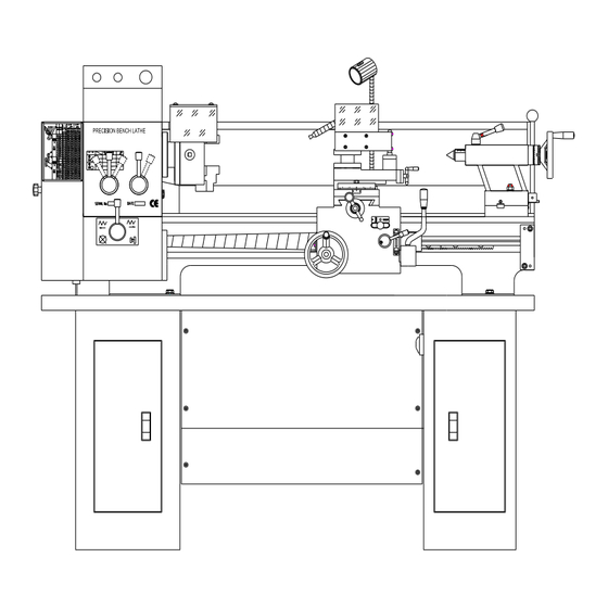
Page 6: Illustrated Features
Steady Rest Follow Rest Face Plate 3 Jaw Chuck Stands with oil tray Splash Guard Illustrated Features Fig 1.Driving system drawing 1. Input Pulley 2. Gear Change... - Page 7 3. Gear Change 4. Gear Change 5. Gear Change 6. Gear 7. Gear 8. Gear 9. Gear 10. Gear 11. Spindle Gear 12. Gear 13. Tool Post Lead Screw 14. Tool Post Nut 15. Tail Stock Lead Screw 16. Tool Post Nut 17.
- Page 8 26. Gear 27. Gear 28. Gear 29. Gear 30. Gear 31. Gear 32. Gear 33. Gear 34. Gear 35. Motor Pulley 36. Gear 37. Gear 38. Gear 39. Gear Lifting&Installation It is recommended that this machine is lifted by the use of a crane or hoisting mechanism as it is very heavy.
- Page 9 Fig 2. Lifting drawing Lifting&Installation cont Please refer to figure 3 when installing this machine. As this lathe is for the most part pre-assembled at the factory, there is not a great deal of assembly for the end user. Line up the four bolt holes with the stand and carefully place the lathe on the stand.
- Page 10 Fig 3. Installation drawing. After installation, be sure to clean the antiseptic coat (used to preserve and protect during shipping) off the guide carriage, tail stock, change gear and pulley with a clean cloth and non-corrosive cleaner. Lubrication Positions...
- Page 11 Fig 4. Lubrication positions drawing. Please refer to the Lubrication chart on the following page in order to properly lubricate and maintain your Lathe. Proper lubrication of any tools, especially Metal Lathes should not be ignored.
- Page 12 Lubrication Positions Cont. Attached List 1: Lubrication Positions Li Attached List 1;Lubrication Positions Li Item Located part Lubrication Lubrication Position Located part Lubrication Oil Methods Period Gears. bush bearing Left trestle Gun oiling Machine oil 0ne year Spindle bearing Lathe head Greasing Grease 1/year...
-
Page 13: Operating Controls
Fig5.Llectrical System Drawing Operating Controls REFER TO THE DIAGRAM BELOW FOR THE BT1324&BT1330 operation controls. - Page 14 Fig 6.Operation Parts Fig. 1. Power source-plug 2. Transmission Box Cover 3. Forward/Reverse Switch for lead screw-Middle position is Neutral 4. Shift Knob-Gear change 6. Shift Knob-Gear change 7. Stop button 8. Chuck 9. Longitudinal-Feed hand wheel 10. Small Carriage Cross Feed hand wheel...
-
Page 15: Threading Chart
11. Tool Post Swivel Nut 12. Tool Post feed hand wheel 13. Auto Feed for Tool Post-Left, Right, Neutral 14. Tool Carriage hand wheel 15. Carriage Auto-Feed Switch 16. START Forward/Reverse Switch 17. Pump Switch 18. Handle Lock for tailstock center 19. -
Page 16: Grounding Instructions
Threading Cutting threads can be performed by the manual use of the change gears and handle 4&5(refer to Operating Controls) Grounding Instructions In the event of a malfunction or breakdown, grounding provides the path of least resistance for electrical current and reduces the risk of electrical shock. - Page 17 not fit the electrical outlet, have the proper outlet installed by a qualified licensed electrician. IMPROPER CONNECTION equipment grounding conductor can result in risk of electrical shock. The conductor wire with the green insulation (with or without yellow stripes) is the equipment-grounding conductor.
- Page 18 SPINDLE BOX V710 GB/T1171-1986 V-belt type 680 皮带 M16*1.5 GB/T812-1988 Spanner nut 圆螺母 16 GB/T858-1988 Lock washer for circular nut 止动垫圈 BT1324&BT1330-02-031 Spindle pulley 皮带轮 30 GB/T894.1-1986 Circlips for shaft-type A 轴用挡圈 6206/P6 GB/T276-1994 Taper roller oearing 深沟球轴承 M5*16 GB/T77-1985 Hexagon socket head screw 内六角螺栓...
- Page 19 6 GB/T7940.4-1995 Oil cup 油杯 11 GB/T894.1-1986 Circlips for shaft-type A 轴用挡圈 BT1324&BT1330-02-040 coller 挡圈 BT1324&BT1330-02-039 Change Gear 挂轮 C BT1324&BT1330-02-042 Sleeve spacer 隔套 D A5*36 GB/T1096-1994 Plain parallel key 平键 BT1324&BT1330-02-041 Sleeve 衬套 B BT1324&BT1330-02-038 Change Gear 挂轮 B BT1324&BT1330-02-043...
- Page 20 BT1324&BT1330-02-044 Output shaft 输出轴 A5*60 GB/T1096-1994 Plain parallel key 平键 BT1324&BT1330-02-045 Gear 齿轮 BT1324&BT1330-02-046 Gear 齿轮 BT1324&BT1330-02-048 Gear 齿轮 BT1324&BT1330-02-049 Sleeve spacer 隔套 E BT1324&BT1330-02-023 Sleeve 压盖 B BT1324&BT1330-02-032 Sleeve 压盖 C BT1324&BT1330-02-011 Sleeve spacer 隔套 A A5*22 GB/T1096-1994 Plain parallel key 平键...
- Page 21 6 GB/T7940.4-1995 Oil cup 油杯 BT1324&BT1330-03-012 Apron body 箱体 8*40 GB/T118-1986 Taper pins 内螺纹锥销 M8*100 GB/T70-1985 Hexagon socket head screw 内六角螺钉 AM8*25JB/T7271.3-1994 Handle sleeve B-plastic 手柄套 BT1324&BT1330-04-019 Handle seat 手柄杆 BT1324&BT1330-03-027 Right shifting fork 拨叉 BT1324&BT1330-03-028 shaft 拨叉轴 BT1324&BT1330-03-001 Base 拨叉座...
- Page 22 Base 轴承座 M5*12 GB/T70-1985 Hexagon socket head screw 内六角螺钉 M14*1.5 GB/T810-1988 Spanner nut 圆螺母 BT1324&BT1330-03-016 Sleeve 护套 BT1324&BT1330-03-003 Sleeve 挡圈 C BT1324&BT1330-附 01-011 Gear 齿轮 BT1324&BT1330-03-002 Sleeve spacer 轴套 5*10 GB/T1096-1994 键 BT1324&BT1330-03-026 Change gear plate 挂轮架 BT1324&BT1330-03-008 Sleeve 连接座...
- Page 23 M6*12 GB/T77-1985 Hexagon socket head screw 内六角螺钉 BT1324&BT1330-02T01-002 偏心套 BT1324&BT1330-02T01-001 开关杆 BT1324&BT1330-02T01-004 连接板 5 GB/T96-1985 Plain washers 平垫圈 M5*12 GB/T818-1985 十字盘头螺钉 BT1324&BT1330-02T01-003 挡板 BT1324&BT1330-01-014 挡屑板 M6*10 GB/T77-1985 Hexagon socket head screw 内六角螺钉 10 GB/T96-1985 Plain washers 平垫圈 M10*50 GB Hexagon head screw 六角螺栓...
- Page 24 M6*8 GB/T77-1985 Hexagon socket head screw 内六角螺钉 M8*30 GB/T77-1985 Hexagon socket head screw 内六角螺钉 BT1324&BT1330-05-003 Chock 镶条 BT1324&BT1330-05-005 Shield 护罩 BT1324&BT1330-05-002 Middle carriage 上拖板 6 GB/T7940.4-1995 Oil cup 油杯 M6*12 GB/T77-1985 Hexagon socket head screw 内六角螺钉 BT1324&BT1330-05-009 Washer 套 M6*20 GB1779-1985 Set screws with cone point 内六角锥端紧定螺钉...
- Page 25 BT1324&BT1330-05-007 Chock 镶块 BT1324&BT1330-05-001 Carriage 大拖板 4*16 GB/T1096-1994 Plain parallel key 平键 4*16 GB/T1096-1994 Plain parallel key 平键 BT1324&BT1330-05-010 Cross feed screw rod 横向丝杠 BT1324&BT1330-05-013 Gear 齿轮 6 GB/T7940.4-1995 Oil cup 油杯 BT1324&BT1330-05-014 Cross feed screw seat 丝杠座 M6*60 GB/T77-1985 Hexagon socket head screw 内六角螺钉...
- Page 26 M10 GB923-1988 Domed cap nuts 盖形螺母 10 GB/T923-1976 Spring washer 弹性垫圈 JB/T7270.4-1994 Sleeve 套 B12*125 JB/T7273.3-1994 Hand wheel 手轮 BT1324&BT1330-04-022 Sleeve 刻度环芯套 BT1324&BT1330-04-021 Spring lamination 簧片 BT1324&BT1330-04-020 Dial 刻度环 M4*20 GB70-85 Hexagon socket head screw 内六角螺钉 BT1324&BT1330-04-023 Flange sleeve 手轮座...
- Page 27 BT1324&BT1330-04-025 Worm shaft 蜗杆 GB/T301-1995 Thrust ball bearing 推力球轴承 51106 BT1324&BT1330-04-010 Worm shaft 蜗杆轴座 M5*12 GB/T70-1985 Hexagon socket head screw 内六角螺钉 30 GB/T858-1988 Lock washer 圆螺母用止动垫圈 M30*1.5 GB/T810-1988 Round nut 圆螺母 M30*1.5 BT1324&BT1330-01-010 Safe shield 丝杠护板(左) M5*10 GB/T70-1985 Hexagon socket head screw 内六角螺钉...
- Page 28 M4*12 GB/T68-1985 Screw 十字沉头螺钉 BT1324&BT1330-04-017 Sleeve 开合轴座 4*28 GB/T1096-1994 Dlain parallel 键 BT1324&BT1330-04-024 Gear shaft 手轮轴 GB/T7940.4-1995 Oil cup 油杯 8 BT1324&BT1330-04-012 Sleeve 齿轴套 内六角锥端紧定螺钉 M5*10 GB/T78-1985 Screw M5*10 BT1324&BT1330-04-001 Apron body 箱体 TAILSTOCK Rooling Center 死顶针 BT1324&BT1330-06-002 Tailstock center sleeve 尾架套筒...
- Page 29 6 GB/T7940.4-1995 Oil cup 油杯 BT1324&BT1330-06A-007 Tailstock 尾架壳体 内六角紧定螺 M10*40 GB/T77-1985 Set screws with cone point 钉 BT1324&BT1330-06-003 Tailstock screw stem 尾架丝杠 BT1324&BT1330-06-011 挡销 4*28 GB/T1096-1994 Plain parallel key 平键 8*25 GB/T117-1986 Taper pins 圆锥销 BT1324&BT1330-06-001 Shaft 偏心轴 6 GB/T7940.4-1995 Oil cup 油杯...
- Page 30 STAND Water pipe 回水管 BT1324&BT1330-07-005 集水盘 M5*8 GB/T819-1985 Screw 十字盘头螺钉 BT1324&BT1330-01-016 油盘 BT1324&BT1330-07-002 Right stand 右底座 Pump switch 水泵转换开关 M5*8 GB/T819-1985 Screw 十字盘头螺钉 锁舌 Door lock 门锁 BT1324&BT1330-07-006 电器安全罩 Water pipe 出水管 BT1324&BT1330-07-007 水泵接管...
- Page 31 Pump 水泵 M5*20 GB/T819-1985 Screw 十字盘头螺钉 M5 GB/T41-1985 螺母 BT1324&BT1330-07-008 Water box 水箱 M6*15 GB/T819-1985 Screw 十字盘头螺钉 BT1324&BT1330-07-003 连接板 M6*10 GB/T819-1985 Screw 十字盘头螺钉 BT1324&BT1330-07-004 连接条 M6 GB/T41-1985 Hexagon thin nuts 螺母 BT1324&BT1330-07-001 Left stand 左底座 A8*30 GB/T1096-1994 Plain parallel key 平键...
- Page 32 Taper pins 弹性销 M5*8 GB/T819-1985 Screw 十字盘头螺钉 BT1324&BT1330-01-019 Safe box 电器安全罩 BT1324&BT1330-01-005 Shaft 销轴 BT1324&BT1330-01-003 Door-knob 锁紧块 BT1324&BT1330-01-001/002 Compound box 车头护罩 Thread table 挂轮表标牌 2.5*5 GB/T827-1986 Rivet 铝铆钉 BT1324&BT1330-03-008 Sleeve 连接座 M5*12 GB/T70-85 Hexagon socket head screw 内六角螺钉 BT1324&BT1330-03-025 Screw 支承螺钉...
- Page 33 DESCRIPTION BT1324&BT1330 8*40 JB/T7274.4-1994 Start-grip knob 星形把手 3*18 GB/T879-1986 Taper pins 弹性销 BT1324&BT1330-01T01-008 Adjusting bolt 调整螺杆 BT1324&BT1330-01T02-002 Sleeve 芯套 M6*8 GB/T77-2000 Screw 平端紧定螺钉 M6 GB/T41-2000 六角螺母 BT1324&BT1330-01T01-004 Screw 轴位螺钉 M6*16 GB/T79-2000 Screw 圆柱端紧定螺钉 BT1324&BT1330-01T01-001 Stand 底座 M12*70 GB/T5780-2000 Screw 六角螺拴...
- Page 34 5*25 GB/T119-2000 Pins 圆柱销 BT1324&BT1330-01T01-002 shaft 锁紧杆 BT1324&BT1330-01T01-003 锁紧螺母 BT1324&BT1330-01T01-005 Cover 上盖 BT1324&BT1330-01T01-006 Bracket 衬垫 BT1324&BT1330-01T01-009 Sleeve 定位套 8*40 JB/T7274.4-1994 Start-grip knob 星形把手 3*18 GB/T879-1986 Taper pins 弹性销 BT1324&BT1330-01T01-009 Bush 定位套 BT1324&BT1330-01T02-003 Adjusting bolt 调整螺杆 BT1324&BT1330-01T01-006 Bracket 衬垫 BT1324&BT1330-01T02-002 Sleeve 芯套...
- Page 35 BT1324&BT1330-01T02-001 Follow rest 跟刀架 Parts Listing-Lathe Handle Parts NO. Description M6*12 GB/T70.1-2000 Hexagon socket head screw BT1324&BT1330-08-003A Block BT1324&BT1330-08-004A Collar M2.5*16 GB/T818-2000 Crossrecessed pan head screws BT1324&BT1330-08-005A M5*30 GB/T70.1-2000 Hexagon socket head screw A5*12 GB/T117-1986 Taper pins BT1324&BT1330-08-001A Shaft BT1324&BT1330-08-008A...
- Page 36 M6 GB/T41-1985 Hexagon nuts M6*16 GB/T79-2000 Screw BT1324&BT1330-08-009A Collar M8*10 GB/T77-2000 Screw 0.8*5*16 GB/T2089-1985 Spring 6.5 GB/T308-1989 Steel ball BT1324&BT1330-08-002A Handle seat 0.8*6*20 GB/T2089-1985 Spring BM10*50 GB/T4141.14-1994 Knob M6*12 GB/T70.1-2000 Hexagon socket head screw BT1324&BT1330-08-007A Bracket BT1324&BT1330-08-006A Collar M6*30 GB/T79-2000...
- Page 37 WARRANTY Warrants every product to be free from defects in materials and agrees to correct such defects where applicable. This warranty covers two years for part and 90 days for labour (unless specified otherwise), to the original purchaser from the date of purchase but does not apply to malfunctions. arising directly or indirectly from misuse, abuse, improper installation or assembly, negligence, accidents, repairs or alterations or lack of maintenance.
Need help?
Do you have a question about the BT1324 and is the answer not in the manual?
Questions and answers