Advertisement
Quick Links
Advertisement

Related Manuals for Bolton Tools BT1340G/1


Summary of Contents for Bolton Tools BT1340G/1
- Page 1 BT1340G/1 BENCH LATHE OPERATION MANUAL...
- Page 2 1. GENERAL SAFETY RULES FOR POWER TOOLS DO NOT ATTEMPT TO OPERATE UNTIL YOU HAVE READ THOROUGHLY AND UNDERSTAND COMPLETELY ALL INSTRUCTIONS, RULES, ETC. CONTAINED IN THIS MANUAL FAILURE TO COMPLY CAN RESULT IN ACCIDENTS INVOLVING FIRE, ELECTRIC SHOCK OR SERIOUS PERSONAL INJURY.
- Page 3 1.2.9 WEAR PROPER APPAREL No loose clothing. Gloves, neckties, rings bracelets, or jewelry to get caught in moving parts. Nonslip footwear is recommended . Wear protective hair covering to contain ling hair. 1.2.10 ALWAYS USE SAFETY GLASSES Also use face or dust mask if cutting operation is dusty. Everyday eyeglasses only have impact –...
- Page 4 Feed work into a blade or cutter against the direction of rotation of the blade or cutter only . 1.2.20 NEVER LEAVE TOOL RUNNING UNATTENDED. TURN POWER OFF. Don’t Leave tool until it comes to a complete stop. The operation of any power tool can result in foreign objects being thrown into the eyes, which can result in severe eye damage .
-
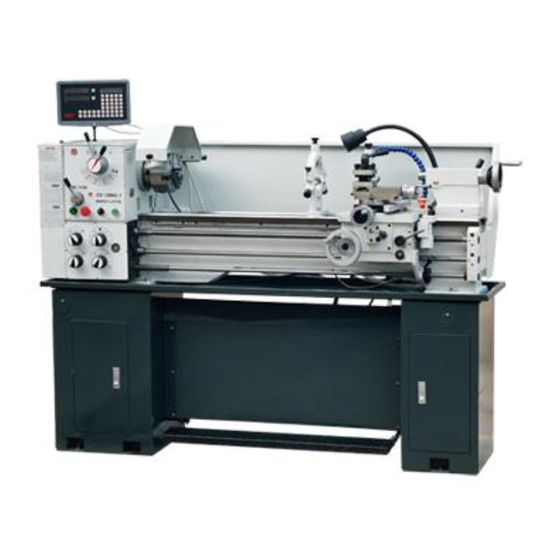
Page 5: Machine Specification
DO ALLOW FAMILIARILY (GAINED FROM FREQUENT USE OF YOUR LATHE) TO BECOME COMMONPLACE. A CARELESS FRACTION OF A SECOND CAN ALLOW FOR SEVERE INJURY. 3.MACHINE SPECIFICATION Bench lathes are especially suitable for machining workshops, tool rooms and repairing workshops to machine shafts spindles, sleeves and disc workpieces of middle or small types. - Page 6 TECHNICAL DATA Capacity Dimension Swing Over Bed ------------------------------------------------- ----12.99"(330mm) Over Cross Slide ------------------------------ ------ --- ------7.68"(195mm) Through Gap -------------------------------------------------18.74" (476mm) Distance Between Centers------------------------------------------39-1/3"(1000mm ) Width --------------------------------------------------------7-3/8"(187mm ) Length ----------------------------------------------------65-1/3"( 1658mm ) Height ---------------------------------------------------11-13/32"( 290mm ) Main Motor ------------------------------------------------------- --------------------2HP Headstock Spindle Bore ---------------------------------------------------------------1-1/4"(38mm) Nose --------------------------------------------------- D 1-4"...
- Page 7 Metric --------------------------------- 0.025-0.69 mm/rev Tailstock Quill Diameter ---------------------------------------1-1/4" (32mm) Travel -------------------------------------------------3-3/4"(95mm) Taper -----------------------------------------------------------M.T.3 Weights (NW/GW) -------------------------------------------------------869lb/1089lb (With machine stand) -------------------------------------------------------------1309lb Packing size (LWH)----------------------------- -----------75.59"*29.92"*29.92" 4.UNLOADING Unpack the wooden case first and use the bed clamping plates and eyebolts to sling the lathe. Position the saddle and tailstock along with the bed to keep the balance.
- Page 8 Electrical wiring diagram 3 phases Single phase 7...
-
Page 9: Lubrication System
SIGN NAME TYPE Motor 3 phase Y90L-4 Single phase YC100L-4 AC magnetic contactor LC1-D129 (3 phase0 LC1-D259(single phase) Relay CA2-DN22 Transformer JBK3-63 Power switch HZ5B-10/2D009 Emergency stop button LA25-01ZS Job button LA25-10 Power indicator light AD11-30/20 5.LUBRICATION SYSTEM (A) Head stock Ensure that the head stock is filled to the level of the relevant oil sight glass with Tellus 32 of Shell oil. -
Page 10: Lubrication Diagram
Fill the oil by taking off the inlet cap, which is fitted at the top on the right hand side of the apron . (D) Change gears Lubricate the change gears with thick machine oil or grease once a month . (E) Other portions There are oil inlets on input shaft bracket of gearboxs , handwheel bracket of apron , feed rod bracket of carriage , saddle , cross slide , toolpost, thread dial... - Page 11 Lubrication table No. Lubrication Number Date Date parts lubricating points filling oil changing oil Input shaft of Once a day gearbox Gearbox First change after 3 months, Headstock then,once a year Apron Carriage Once a day Tool post Once a day Thread dial Once a day...
- Page 12 Operation diagram 1.Forward/reverse switch 2.Handle 3.Feed direction selector 4.Four steps speed selector 5.Low/high speed selector 6.Knob component 7.Steady rest 8.Longitudinal traverse hand wheel 9.cross traverse hand wheel 10.Follow rest 11.Toolpost handle 12.Toolpost traverse handle 13.Tailstock quill clamping lever 14.Tailstock quill traverse hand wheel 15.Tailstock set-over screw 16.Thread dial indicator 17.Controlling lever 18.Machine stand 19.Thread cutting engagement lever 20.Feed axis selector 21.Controlling rod...
- Page 13 6.1SPINDLE SPEED CONTROL (refer to operation diagram) A. Identification before operation (1) Ensure that lubrication has been carried out in accordance with the lubrication charts. (2) When rotating the spindle, it is mechanized to the gear box and apron. Check that the forward / reverse switch (No.
- Page 14 6.2 SPINDLE NOSE (CAM LOCK D1-4”) MOUNTING OF CHUCKS, FACEPLATES AND OTHER SPINDLE MOUNTED ATTACHMENTS Ensure that the location faces on both nose and attachment are scrupulously cleaned. Check that all the cams are in the release position (fig . 1) Mount the attachment on to the spindle nose and lock each cam by turning it clockwise using the key provided.
- Page 15 handle (No.12) The carriage is anchored by turning the carriage lock in clockwise direction. (B) Replacement of change gears. Open the end cover firstly, Then loose both the hexagon nut of the clamping bolt and the clamping screw of the swing frame to exchange the transmission shaft gear with another gear.
- Page 16 Longitudinal and cross feed table in metric lead screw. (2) Thread table a. Thread table for imperial lead screw. 15...
- Page 17 b. Thread table for metric lead screw. 16...
- Page 18 (E)Threading dial indicator Threading dial indicator (No.16) is installed on the right hand side of apron. The indicator is used for thread cutting to engage with lead screw . To cut threads on the chart, close the lead screw nut at the appointed line of the dial according to the indicator chart, Ensure the appropriate dial line coincide exactly with fixed point each pass .
-
Page 19: Lathe Alignment
gear of mesh with the lead screw tightly when out in use. a. IMPERIAL THREADS ON IMPERIAL LEADSCREW MACHINES OR METRIC THREADS ON METEIC LEADSCREW MACHINES For these threads it is recommended that the thread dial indicator be used this allows the half nut of lead screw to be engaged at the end of each thread cutting pass, provided that are reengaged in accordance with the indicator table mounted on the left hand side of the apron . - Page 20 (B) Saddle strip Wear on the rear saddle gib strip (A) may be accommodated by adjustment of the socket head set screws . The procedure for adjustment is to first release the hexagon nuts (B) and turn the socket head set screws(C) slightly in clockwise and then reclamp the hexagon nuts, Care should be taken to avoid over adjustment 45 turn at the socket head set...
- Page 21 the end edge of the feed rod . Turn the socket head cap screw in a clockwise direction as require. Care should be taken to avoid over adjustment ; every 45 turn at the socket head cap screw represents approximately 0.125mm (0.05") taken up of back lash .
-
Page 22: Caution During Operation
lubrication plan sheet) to keep the machine properly lubricated. 3) Check all the running parts not too tight, or loose. Bearing of headstock, longitudinal and cross feed, tool holders etc would be exmined and adjusted by hand or proper fitness. 4) Check the sensitivity &... - Page 23 To feel the temperature of motor bearing at the case of full load. 3) Noise and vibration: If you find the noise and vibration of the machine are abnormal or irregular. Stop the machine immediately for inspection and adjustment. 4) Quality of products: If you discover the quality of products is out of limit, stop the machine at once for finding the causes of defects.
- Page 24 2) Electrical system: Carefully examine the connection of all electrical wires, terminals and switches, which occasionally have been damaged by chips or others. 8.4.3SEMI-YEARLY INSPECTION: 1) Change oil in gear box: Remove the used oil from gear box of headstock, feed and replenish with fresh oil.
- Page 25 9.TROUBLE SHOOTING TROUBLE PROBABLE CAUSES REMEDY Overheat 1.Oil level in headstock is Check the oil level and headstock too low or too high. replenish or discharge bearing the oil to the proper level. 2.Quality and viscosity of oil Replace the oil with is wrong.
- Page 26 Chatter 18.Clamp of workpiece in Tighten clamp. from loose status. 19.Spindle bearing thrust too Adjust bearing thrust. loose. 20.Headstock is not tight Tighten headstock with bedway. screw. 21.Excess clearance between Adjust carriage back carriage clamp. 22.Excess clearance in cross Adjust carriage back or compound slide.
- Page 27 Misalliance 33.Incorrect position of cam. Adjust cam and lock in chuck with main proper position. spindle. Uneasy to cut the 34.Excessive clearance of Adjust the thrust nut of thread lead screw in axial direction. the lead screw holder. 35.Excessive clearance Adjust slide between saddle or cross slide...
- Page 28 27...
- Page 29 Bed Assembly Index No. Part No. Description Size GB/T70 Hex Socket Cap Screw M10×40 GB/T41 Hex Nut GB/T881 8×75 CZ1340G-01-015 GB/T77 Set Screw M10×16 CZ1340G-07-028 GB/T5780 Hex Cap Bolt M12×50 CZ1340G-01-016 Rack GB/T117 5×25 GB/T70 Hex Socket Cap Screw M6×20 CZ1340G-01-017 Rack CZ1340G-07-058...
- Page 30 Index No. Part No. Description Size CZ1340G-01-005 Motor Mounting Plate CZ1340G-02-001 Lock Nut CZ1340G-00-005 Cover CZ1340G-02-002 Screw CZ1340G-02-002 Screw 29...
-
Page 32: Headstock Assembly
Headstock Assembly Index No. Part No. Description Size Qty. GB/T70 Screw M6×16 CZ1340G-02-009 Screw CZ1340G-02T01-001 Cover CZ1340G-02-008 Gasket GB/T77 Screw M6×8 CZ1340G-02-031 Plug GB/T7757.2 O-Ring 41.3×3.1 GB/T276 Bearing 6204/P6 CZ1340G-02-030 Gear Shaft GB/T1096 6×56 CZ1340G-02-032 Gear CZ1340G-02-029 Gear CZ1340G-02-028 Gear CZ1340G-02-027 Collar CZ1340G-02-067... - Page 33 Index No. Part No. Description Size Qty. GB/T70 Screw M6×25 CZ1340G-02-011 Front Cover CZ1340G-02-012 Gasket GB/T279 Bearing 30212/P5 Gb/T894.1 C-Clip CZ1340G-02-036 Gear CZ1340G-02-033 Gear GB/T1096 8×18 CZ1340G-02-037 Gear GB/T894.1 C-Clip GB/T297 Bearing 30210/P5 CZ1340G-02-062 Collar CZ1340G-02-005 Gasket CZ1340G-02-004 Rear Cover GB/T70 Screw M6×25...
- Page 34 Index No. Part No. Description Size Qty. GB/T879 3×10 ×18 GB/T1096 GB/T7757.2 O-Ring 13.8×3.1 CZ1340G-02-056 Washer GB/T10708.3 Oil Seal 24×32×5 CZ1340G-02-057 Gear GB/T97.1 Washer GB/T41 CZ1340G-02-024 Shift Lever GB/T7757.2 O-Ring 11.8×1.8 CZ1340G-02-020 Shift Fort GB/T879 5×32 CZ1340G-02-023 Shaft CZ1340G-02-040 Gear 33...
- Page 35 31...
- Page 36 Inlaid Block Assembly Index No. Part No. Description Size Qty. CZ1340G-02-046 Handle Body GB/T308 Steel Ball GB/T2089 Spring 0.6×3×18 GB/T77 Screw M6×8 GB/T71 Screw M6×12 CZ1340G-02-068 Handle JB/T7271.5 Lever Sleeve BM8×40 CZ1340G-02-044 Handle Block CZ1340G-02-043 Handle Body GB/T308 Steel Ball GB/T2089 Spring 0.9×4×20...
- Page 37 32...
- Page 38 Gearbox Assembly Index No. Part No. Description Size Qty. GB/T70 Screw M6×16 CZ1340G-03-007 Shaft Cover CZ1340G-07-008 Gear(30T,54T,56T,57T, 60T,63T,66T,69T,7 CZ1340G-07-013 Shaft GB/T1096 5×18 GB/T1096 5×45 GB/T894 C-Clip GB/T276 Bearing 6004 CZ1340G-07-018 Gasket CZ1340G-07-021 Cover GB/T70 Screw M5×12 CZ1340G-07-022 Shaft GB/T117 3×32 GB/T70 Screw M6×20...
- Page 39 Gearbox Assembly Index No. Part No. Description Size Qty. CZ1340G-07-003 Shaft GB/T70 Screw M10×16 GB/T3452.1 O-Ring 9.5×1.8 D97-4-20 Locking Connector of Tube CZ1340G-07-002 Gear CZ1340G-07-003 Shaft GB/T70 Screw M10×16 GB/T3452.1 O-Ring 9.5×1.8 D97-4-20 Locking Connector of Tube GB/T70 Screw M8×25 GB/T117 6×25 GB/T9877.1...
- Page 40 Index No. Part No. Description Size Qty. GB/T879 4×25 GB/T1160.1 Oil Sight Glass CZ1340G-07-036 Handle Body GB/T308 Steel Ball GB/T2089 Spring 1×5×20 GB/T77 Screw M8×10 CZ1340G-07-041 Panel 35...
- Page 41 36...
- Page 42 Apron Assembly Index NO. Part NO. Description Size GB/T5780 Screw M6*10 CZ1340G-04-030 Washer CZ1340G-04-016 Gear GB/T1096 5*12 CZ1340G-04-015 Shaft GB/T3452.1 O-Ring 20*2.4 CZ1340G-04-013 Gear GB/T879 5H30 CZ1340G-04-004 Gear Shaft GB/T879 5*30 CZ1340G-04-005 Gear CZ1340G-04-047 Bracket GB/T70 Screw M6*16 CZ1340G-04-001 Apron box GB/T3452.1 O-Ring 12*2.4...
- Page 43 Index NO. Part NO. Description Size GB/T77 Screw M5*12 CZ1340G-04-023 Gear JB/T7941.1 Oil Sight CZ1340G-04-041 Oil Plug CZ1340G-04-033 Bushing CZ1340G-04-026 Shaft GB/T70 Screw M5*12 CZ1340G-04-012 Shaft CZ1340G-04-011 Gear CZ1340G-04-010 Washer GB/T70 Screw M6*10 GB/T83 Screw M5*5 GB/T77 Screw M6*10 CZ1340G-04-034 CZ1340G-04-018 Half Nut GB/T5781...
- Page 44 39...
- Page 45 Saddle and Cross Slide Assembly Index NO Part NO Size Description JB/T4141.5 M8*63 Handle CZ1340G-05-023 Screw CZ1340G-05-022 Washer CZ1340G-05-021 Handle Wheel CZ1340G-05-038 Dial Ring GB/T77 Screw M6*8 GB/T70 Screw M6825 GB/T301 Bearing 51104 CZ1340G-05-020 JB/T7940.4 Oil Ball GB/T5781 Screw M8*20 CZ1340G-05-013 Strip CZ1340G-05-039...
- Page 46 41...
-
Page 47: Tool Post Assembly
Tool Post Assembly Part NO Description Size Index NO Knob M1050 JB/T7271.5 JB/T7271.6 Handle Rod CZ1340G-05-026 Lock Nut CZ1340G-05-024 Washer GB/T83 Screw M1040 Post Base CZ1340G-05-029 Screw CZ1340G-05-025 GB/T78 Screw M610 CZ1340G-05-030 Stop 0.4418 GB/T2089 Spring CZ1340G-05-028 Top Slide JB/T7940.4 Oil Ball GB/T78-85 Screw... - Page 48 43...
- Page 49 Tailstock assembly Index No. Part No. Description Size Qty. CZ1340G-06-020 Base CZ1340G-06-017 Screw CZ1340G-06-018 Collar GB/T879 5×26 GB/T41 GB/T79 Screw M8×35 CZ1340G-06-019 Shaft JB/T7271.5 Knob BM10×50 CZ1340G-06-012 Lever JB/T7271.5 Knob BM8×40 CZ1340G-06-013 Screw CZ1340G-06-015 Shaft CZ1340G-06-014 Screw JB/T7940.4 Oiler CZ1340G-06-004 GB/T70-85 Screw M4×12...
- Page 50 45...
- Page 51 Electric Box Assembly Index No. Part No. Description Size Qty. CZ1340G-09-001 Door of electrical box CZ1340G-09-007 CZ1340G-09-005 Panel CZ1340G-09-011(1) Wiring diagram XB7-EA.1 Green button XB2-ES542 Emergency switch XB7-EV6 Indicator GB/T818 Screw M4×8 LC1-D259 Contactor GB/T818 Screw M4×12 CZ1340G-09-006 Label GB/T41 GB/T818 Screw M4×16...
- Page 52 47...
- Page 53 Follow Rest Index No. Part No. Description Size JB/T7274.4 Knob 8×40 GB/T879 3×18 CZ1340G-05T03-010 Bushing CZ1340G-05T2-003 Screw CZ1340G-05T03-008 Brass Finger CZ1340G-05T02-002 Sleeve GB/T77 Set Screw M6×8 GB/T79 Set Screw M6×16 GB/T6170 GB/T70 Hex Socket Cap Screw M8×45 CZ1340G-05T02-001 Base Casting 48...
- Page 54 49...
- Page 55 Steady Rest Description Index No. Part No. Size JB/T7274.4 Knob 8×40 GB/T879 3×18 CZ1340G-05T03-009 Screw CZ1340G-05T03-011 Sleeve GB/T78 Set Screw M6×8 GB/T6170 CZ1340G-05T03-007 Bolt M6×30 GB/T79 Set Screw M6×16 CZ1340G-05T03-003 Base Casting CZ1340G-05T03-002 Clamp Screw CZ1340G-05T03-001 Clamp Pad GB/T96 Flat Washer GB/T6170 GB/T119 A5×25...
Need help?
Do you have a question about the BT1340G/1 and is the answer not in the manual?
Questions and answers