
Subscribe to Our Youtube Channel
Related Manuals for Bolton Tools BT1337G


Summary of Contents for Bolton Tools BT1337G
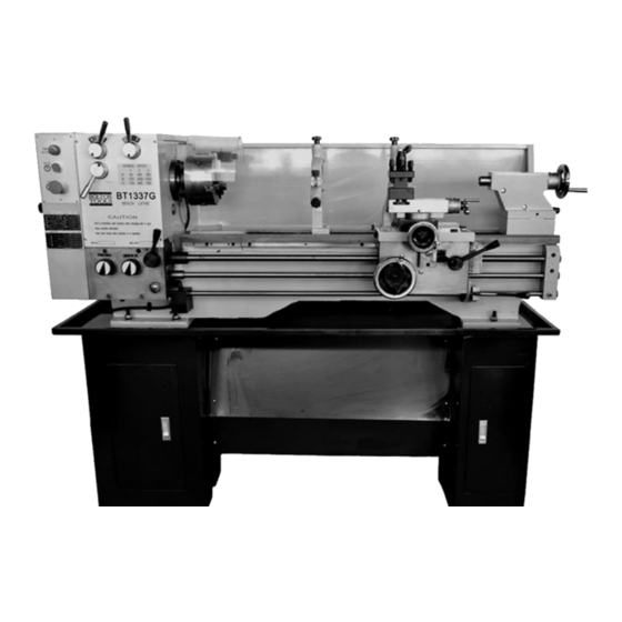
- Page 1 OPERATOR’S MANUAL BENCH LATHE MODEL: BT1337G BOLTON TOOLS 1136 SAMUELSON ST. CITY OF INDUSTRY, CA 91748...
- Page 2 Many thanks for purchasing our BT1337G - Bench Lathe. Before operating, make sure you study the manual to have a better understanding of the operating procedures. This manual will guide you through assembly, will cover general maintenance, and review safety considerations.
-
Page 3: Table Of Contents
Table of Contents 1. SPECIFICATION ..........................4 2. STANDARD ACCESSORY ......................... 4 3. OPTIONAL ACCESSORY ........................4 4. ELECTRICAL SYSTEM ........................4 4.1 ELECTRIC PRINCIPLE CHART ...................... 5 4.2 WIRE CHART ..........................6 4.3 DESCRIPTION ..........................8 5. INSTALLATION ..........................8 5.1 FOUNDATION .......................... -
Page 4: Specification
1. SPECIFICATION (1) Swing over bed 12.99〞 (2) Swing over gap 19.09〞 (3) Swing over saddle 8.46〞 (4) Distance between centers 37〞 (5) Length of bed 58〞 (6) Width of bed 7.17〞 (7) Hole through spindle 1.5〞 (8) Tailstock barrel travel 3.94〞... -
Page 5: Electric Principle Chart
Voltage/Phase Single Phase Three Phase 110V 220V 7.5A 380V 4.1 ELECTRIC PRINCIPLE CHART THREE PHASES SINGLE PHASE... -
Page 6: Wire Chart
4.2 WIRE CHART THREE PHASE... - Page 7 SINGLE PHASE...
-
Page 8: Description
4.3 DESCRIPTION SIGN NAME SIGE NAME Motor Jog switch Transformer Pulley cover limiting switch Indicator light Chuck cover limiting switch Work light Brake switch Stop switch Heat relay 5. INSTALLATION? CAUTION: THE MACHINE MUST BE SECURED, FIRM AND STABLE. DON’T TURN DOWN OR MAKE ANY SUDDEN MOVEMENT WITHOUT INSPECTION BECAUSE OF SHAKING, WIND POWER, LASHING OR OTHER EXPECTED OUTER POWER OR INTERNAL MOVEMENT FORCE (SUCH AS FORCE, MOTOR... -
Page 9: Lifting
Fitting dimension without stand 5.2 LIFTING Lifting the lathe as the following figure shows. Put the mats in which the lifting tools connect before lifting the lathe, to avoid damaging the machine’s surface. The lathe net weight 330kg (728lbs), stand weight 60kg (132lbs). You must keep the machine in balance to avoid tilting. -
Page 10: Leveling
6. LEVELING The lathe should be kept perfectly leveled at all times. Leveling procedure: A. Longitudinal leveling After the bedways are dry, remove the base screw. Place a 6” precision machinist level over working table in a longitudinal direction (bed length direction). Move the working table at the headstock end along bed length direction. -
Page 11: Lubricating Chart
CAUTION: THE LOW PRECISION SPIRIT LEVEL MUST NOT BE USED. SCHEDULE OR PERIODICLY LEVEL CHECK AS A PART OF YOUR MAINTENANCE SCHEDULE. 7. LUBRICATION CHART CAUTION: LUBRICATION IS AN IMPORTANT FACTOR OF MACHINE MAINTENANCE. THE QUANTITY OF LUBRICATION OIL MUST BE MODERATE. -
Page 12: Operating Instrument
8. OPERATION INSTRUCTION 5. Gap Slide 10. Sleeve clamping lever 11. Tailstock 12. Tailstock clamping lever 13. Adjusting screw 14. Three rod support seat 15. Chip pan 16. Control lever 17. Threading dial 18. Half nut lever 19. Cross/longitudinal feed lever 20. Apron 21. -
Page 13: Headstock
Work piece diameter Cut speed (RPM) Cut depth (MM) Feed amount (MM/Turn) ≥ø150 <160 <0.5 <0.1 ≥ø100-150 <200 <0.5 <0.1 ≥ø50-100 <400 <1 <0.15 ≥ø30-50 <1000 <1.5 <0.15 < Ø30 <1300 <1 <0.1 NOTE: WHEN THE RATE OF THE OUTSTANDING AND DIAMETER OF WORK PIECE IS OVER 4”, THE DEPTH OF CUT AND FEED AMOUNT SHOULD BE LESS. -
Page 14: Main Spindle Rotation
CAUTION: DON’T CHANGE SPEED WHEN THE SPINDLE IS RUNNING. 8.4 MAIN SPINDLE ROTATION Starting, stopping, forward and reverse of spindle can be made merely by the control lever. When using the control rod, pull the lever in the headstock direction, then pull up and down. Control lever on the top position Control lever in the middle position Control lever in the bottom position... - Page 15 Half nut must be kept engaged to leadscrew at all times, when the thread is being cut. Every time you are finished cutting, move tool back and reverse the motor. Then take the tool to the start-cutting position and begin the next process. Continue the process until you have completed the threads.
-
Page 16: Carriage
B. Table for inch lead screw. 8.6 CARRIAGE The function of the carriage is firmly to support the tool post and carry it, by moving in longitudinal and cross direction. 8.6.1Power feed For external turning and facing, turn lever (28) on the gear box to “left” to make the feed rod rotate. -
Page 17: Threading Dial
middle and engage the half nut. If done correctly, you will achieve the lead screw rotating and the carriage to move left and right. While the cross/longitudinal feed lever is in the feed position, the half nut lever (B) can be engaged, safety interlock mechanism will prevent simultaneous engagement of (A) and (B). -
Page 18: Compound Slide
The main function of tool post is to fix tool, if necessary. Tool post may fix more than one tool (at most 4). Tool thickness must be less than tool groove. When installing a tool again, you should confirm the tool head direction to the work piece revolving center line. Use an iron spacer to adjust. -
Page 19: Turn On The Electrical And The Spindle Doesn't Rotate
CAUTION: BEFORE CHECKING, PLEASE TURN OFF THE ELECTRICAL POWER. 10.1 Turn on the electrical and the spindle doesn’t rotate. A) The voltage is not right and the main switch turned off. Please adjust the input voltage and turn on the main switch. B) The fuse in the electric box is brown. -
Page 20: Maintenance
11. MAINTENANCE Please always keep the machine in good condition. It is advisable to say maintenance is better than repair. 11.1 Daily maintenance A) Before using every day, please pour the oil and lubricate all the moving parts. B) If the spindle temperature is too high or machine too noisy, please stop the machine and check it in order to keep its precision. - Page 22 Index Part No. Description QTY. CM1224C-01-011 Fixing block JB/T7940.4 Oil cup 6 GB/T70 Screw M8×25 GB/T879 Spring pin 5×25 GB/T77 Screw M8×20 GB/T41 Nut M8 CM1237CHG-01-009 Feeding rod CM1237CHG-01-013 Switch lever CM1224C-01-015 Switch cover GB/T65 Screw M6×12 CM1224C-01-014 Eccentric block GB/T77 Screw M6×6 GB/T70...
- Page 23 GB/T5780 Bolt M8×25 Index Part No. Description QTY. GB/T96 Washer 8 Y90L-4 Motor 1.5kw CM1224C-02-042 Bolt CM1224C-02-005 Motor seat CM1224C-02-006 Motor rest CZ1237A-00-001 Puller cover GB/T5783 Bolt M12×90 GB/T6172 Nut M12 GB/T96 Washer 12 GB/T70-85 Screw M8×30 GB/T879 Spring pin 3×5 GB/T1096 Key B5×18 CM1224-06-005...
- Page 25 Index No. Part No. Description QTY. CZ1237G-02-055 Gasket CZ1237A-02T01-001 Cover CM1224C-03-034 Oil fill plug GB/T70 Screw M6×25 CZ1237G-02-024 Round fork GB/T894.2 Retaining ring (external) 25 CZ1237G-02-025 Input shaft GB/T1096 Key 8×80 GB/T65 Screw M3×8 GB/T1096 Key 5×14 GB/T1096 Key 8×20 CZ1237G-02-022 Gear CZ1237G-02-021...
- Page 26 GB/T1096 Key 8×20 Index No. Part No. Description QTY. CZ1237G-02-029 Gear GB/T276 Bearing 6204P6 CZ1237G-02-034 Spindle GB/T1096 Key 8×80 GB/T297 Bearing 30211P5 CZ1237G-02-031 Gear CZ1237G-02-033 Gear CZ1237G-02-032 Gear CZ1237G-02-037 Gear GB/T1160 Oil level indicator GB/T1096 Key 8×70 GB/T65 Screw M6×8 GB/T70 Screw M8×30 CZ1237G-02-035...
- Page 27 CZ1237G-02-049 GB/T879 Spring pin 4×20 CZ1237G-02-050 Fork Index No. Part No. Description QTY. GB/T119 Pin 8×26 GB/T70 Screw M10×30 CZ1237G-02-001 Adjusting bar CZ1237G-02-005 Shaft CZ1237G-02-007 Collar GB/T894.2 Retaining ring (external) 20 GB/T70 Screw M10×16 GB/T7757.2 O-Ring gasket 10×1.8 CZ1237G-02-008 Washer CZ1237G-02-006 Gear CZ1237G-02-038...
- Page 29 Index No. Part No. Description Qty. GB/T70 Screw M6×12 CM1224C-03-008 Washer CM1224C-03-009 Gear GB/T1096 Key 5×14 CM1224C-03-007 Shaft GB/T1567 5×3×6 GB/T70 Screw M6×10 CM1224C-03-010 Bearing cover GB/T276 Bearing 6003 CM1224C-03-013 Duplex gear CM1224C-03-014 Duplex gear CM1224C-03-012 Gear sleeve CM1224C-03-033 Gear box CM1224C-03-011 Sleeve CM1224C-03-049...
- Page 30 Part No. Description Index No. Qty. GB/T894.1 Retain ring (external) 15 CM1224C-03-050 Cover CM1224C-03-032 Gear CM1224C-03-031 Sleeve CM1224C-03-030 Shaft GB/T70 Screw M8×25 GB/T879 Pin 5×20 CM1224C-03-042 Oil pipe CM1224C-03-043 Oil pipe GB/T894.1 Retain ring GB/T276 Bearing 6201-z CM1224C-03-005 Shaft CM1224C-03-006 Gear GB/T1096 Key 5×14...
- Page 32 Index No. Part No. Description Qty. GB/T70-85 Screw M6×12 CM1224C-03-008 Washer CZ300A-03-001 Gear M=1.25,Z=30,60,64,70 GB/T1096 Key 5×14 CZ300A-03-017 Inputting shaft CM1224C-03-010 Bearing cover GB/T276-94 Bearing6003 CZ300A-03-018 Gear M=2,Z=18 CZ300A-03-026 Sleeve GB/T894.1-85 Retain ring (external) 32 CZ300A-03-020 Duplex gear M=2,Z=36/27 Gb/t1096 Key 6×16 CZ300A-03-021 Duplex gear M=2,z=22/25...
- Page 33 GB/T879 Pin 5×20 CZ300A-03-040 CZ300A-03-034 Oil cover CZ300A-03-024 Gear GB/T879 Pin 5×12 CZ300A-03-025 Duplex M=2,Z=18/36 GB/T896-86 Retain ring (external) 12 CZ300A-03-030 Gear M=2,z=27 GB/T879 Pin 5×30 GB/T301 Bearing 8103 CZ300A-03-031 Sleeve GB/T810 Nut M20×1.5 CZ300A-03-008 Shaft CZ300A-03-052 Fork CZ300A-03-053 Fork CZ300A-03-012 Fork GB/T879...
- Page 34 CM1224C-04-013 Lever JB/T7271.5 Grip of lever GB/T308 Steel ball 6.5 GB/T2089 Compression spring 1×5×20 GB/T73 Screw M8×5 CZ300A-02-048 Indicator...
- Page 36 Index No. Part No. Description Qty. JB/T7270.1 Handle BM8×63 CM1224-04-011 Handwheel CM1224-06-007 Spring GB/T308 Steel ball 6 CM1224-04-013 Indicate ring GB/T70 Screw M6×16 CM1224-04-014 Handwheel seat GB/T7940.4 Oil cup 6 CM1224-04-015 Box GB/T879 Pin 5×60 CM1224-04-012 Gear CM1224-04-016 Gear GB/T879 Pin 5×30 CM1224-04-010 Shaft CM1224-04-037 Washer...
- Page 37 Index No. Part No. Description Qty. CM1224-04-002 Safe guide piece CM1224-04-008 Gear GB/T119 Pin A6×30 CM1224-04-009 Gear GB/T894.1 Retain ring (external) 16 CM1224-04-019 Clutch CM1224-04-003 Handle CM1224-04-036 Knob GB/T879 Pin 5×40 CM1224-04-004 Rod GB/T77 Screw M8×8 CM1224-04-024 Pin CM1224-04-026 Half nut seat GB/T70 Screw M6×8 CM1224-04-025 Half nut...
- Page 39 Index No. Part No. Description QTY. CM1224C-05-003 Saddle CM1224C-05-044 Wiper GB/T818 Screw M5×12 GB/T70 Screw M8×25 GB/T41 Nut M8 GB/T78 Screw M8×22 CM1224C-05-041 Wiper GB/T70 Screw M6×16 CM12224C-05-040 Block slide CM1224C-05-032 Locking block GB/T95 Washer 10 GB/T5780 Bolt M10×60 GB/T879 Pin 5×20 CM1224C-05-039 Gear...
- Page 41 Index No. Part No. Description QTY. CM1224C-05-031 Handle CM1224C-05-030 Handle CM1224C-05-029 Handwheel GB/T77 Screw M6×16 GB/T308 Steel ball6 CM1224C-06-007 Pressure spring CM1224C-05-028 Graduation collar GB/T810 Nut M10×1 GB/T301 Bearing 51100 GB/T70 Screw M4×30 CM1224C-05-027 Leadscrew seat CM1224C-00-006 Indicator plate JB/T7940.4 Oil cup 6 CM1224C-05-025 Leadscrew...
- Page 43 Index No. Part No. Description QTY. GB/T9204.1 Center M.T.3. CM1224C-06-002 Tailstock quill CM1224C-06-021 T-Key CM1224C-06-004 Nut of leadscrew GB/T78 Screw M6×10 CM1224C-06-001 Tailstock CM1224C-06-003 Leadscrew GB/T119 Pin 5×8 CM1224C-06-022 Sleeve GB/T879 Spring pin5×24 CM1224C-06-005 Leadscrew seat JB/T7940.4 Oil cup GB/T70 Screw M6×16 CM1224C-06-006 Graduation collar...
- Page 45 Index No. Part No. Description QTY. RVV3×25 Plug wire DTH13-20 Finger-protected switch RVV×25 Switch cord “needle” connector wire Metal hoseΦ10 BVR1.5 Copper wire BVR1 Copper wire JXB15-19 Wiring panel Plug in unit 4.8 Sleeve of plug in unit Fuse core 2A Fuse OT1.5-4 Connector wire...
- Page 47 Index No. Part No. Description QTY. T101 JB/T727404 Star handle M8×30 T102 GB/T879 Pin 3×16 T103 CM1224C-05T02-003 Collar T104 CM1224C-05T02-002 Adjusting screw T105 CM1224C-05T02-004 Sleeve T106 CM1224C-05T02-005 Clamping block T107 GB/T78 Screw M6×8 T108 GB/T71 Screw M6×16 T109 GB/T6170 Nut M6 T110 GB/T70 Screw M8×35...
- Page 49 Index No. Part No. Description QTY. T201 JB/T7274.4 Star handle M8×30 T202 GB/T879 Pin 3×16 T203 CM1224C-05T02-003 Collar T204 CM1224C-05T02-002 Adjusting screw T205 CM1224C-05T02-004 Sleeve T206 CM1224C-05T02-005 Clamping block T207 GB/T71 Screw M6×16 T208 GB/T6170 Nut M6 T209 GB/T78 Screw M6×8 T210 GB/T27 Bolt M6×25...
Need help?
Do you have a question about the BT1337G and is the answer not in the manual?
Questions and answers