Table of Contents
Advertisement
Advertisement
Table of Contents

Related Manuals for B&K Reference 4420


Summary of Contents for B&K Reference 4420
- Page 1 B & K Components Ltd. P/N 12692...
- Page 2 B&K Components, Ltd., 2100 Old Union Road, Buffalo, New York 14227...
- Page 3 Safety Precautions Purpose and function Design and construction Features Rear panel view Rear panel description Control muting Level controls Outputs Inputs System installation Making the connection Troubleshooting Care and cleaning Specifications Warranty Manual and Power cord Page 1 Page 2 Page 3 Page 3 Page 3...
- Page 4 Turn amplifier ‘off’ when plugging in or unplugging input and speaker cables!!! The Reference 4420 is equipped with raised feet so that continuous ventilation can be maintained. They help to maintain acoustic feedback into the amplifier at a minimum.
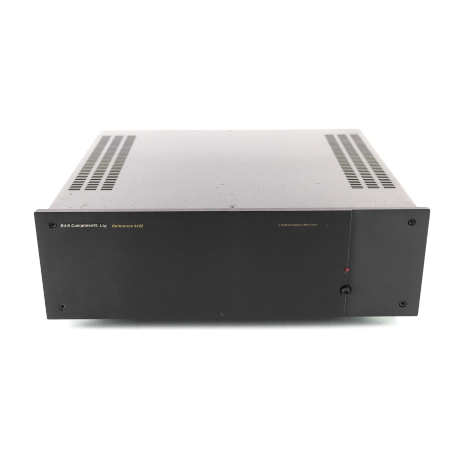
- Page 5 The Reference 4420 is a compact, very efficient, two channel power amplifier. It is designed to be used in all types of audio or audio/video systems. The Reference 4420 utilizes high quality electronic circuitry to achieve an environment wherein a detailed, transparent, and highly musical sound can be realized. The high...
- Page 6 1. AC fuse holder 2. AC Input receptacle 3. Speaker outputs 4. Balanced inputs 1. AC fuse holder - 2. AC Input receptacle - For attaching the supplied AC power cord to the 3. Speaker outputs - 5. RCA inputs (unbalanced) 6.
- Page 7 The preamplifier’s control output, such as is provided with B&K series preamplifiers, can be utilized to provide a control signal to the Reference 4420. If more than one amplifier is being controlled, the control signal can be extended to include...
- Page 8 If the control function is desired, each unit in the system must remain connected at all times and the control must be enabled. To enable the control function, the CTRL ENABLE button must be out for each controllable amplifier in the system. For more information on the amplifiers output status under various control conditions, refer to the table below.
- Page 9 Five way binding posts are provided. One pair for each channel. They are designed to accept a banana-type plug or spade lug connector (shown below) and are color coded for easy identification. The red (+) post should always be connected to the speakers (+) jack.
- Page 10 Balanced - XLR type connectors accept line input from the preamplifier’s balanced output connectors. There are two input connectors, one for each channel, that may be used to connect the amplifier to the preamplifier. Balanced cable connector Operation - For balanced operation, ensure the balanced switch between the balanced inputs on the rear of the amplifier is in the ‘on’...
- Page 11 There will most likely be a number of cables involved in the installation of your home entertainment system. Pre-planning is essential in order to maximize system efficiency. We recommend the following as a means of helping you reach that goal: Make a diagram of your proposed system by laying out the relative location of each component in the system.
- Page 12 Connect the audio cables from your preamplifier’s output to the corresponding input connector on the amplifier. Connect the wires from your speakers to the appropriate output on the amplifier. It is absolutely essential that you observe correct polarity in these connections. Double check all connections.
- Page 13 PROBLEM No sound (‘on’ LED not illuminated) No sound on some or all selected channels (‘on’ LED illuminated) Sound lacks direction, bass weak Loud hum or buzz on one or more channels Low output from amplifier Channel sounds distorted and low in output ** Note : If unit continues to blow power inlet fuses, have it serviced...
- Page 14 Power rating: 8 ohms 4 ohms Frequency response Input sensitivity THD (S+N) Input impedance Damping factor Current (peak to peak) Slew rate Dynamic headroom S/N (A-weighted) Voltage gain Line voltage Dimensions (O.A.) Weight Power consumption Replacement fuses 225 watts @ 1 kHz 350 watts @ 1 kHz 5 Hz - 45 kHz 1.4 Volts...
- Page 15 B&K Components Ltd., referred to herein as B&K, warrants your B&K equipment against all defects in material and workmanship for a period of five years from the date of purchase. This warranty applies only to the original purchaser and only to equipment in normal residential use and service. Defective equipment must be returned to B&K, prepaid, accompanied by sufficient payment to cover the cost of return shipping and handling, and will be repaired or replaced at the discretion of B&K whose decision as to the method of reparation will be final.
- Page 16 B&K Components, Ltd. 2100 Old Union Road Buffalo, New York 14227 716-656-0023 www.bkcomp.com...
Need help?
Do you have a question about the Reference 4420 and is the answer not in the manual?
Questions and answers