Advertisement
Quick Links
Advertisement

Subscribe to Our Youtube Channel
Related Manuals for CUSHCRAFT LFA-2M16EL


Summary of Contents for CUSHCRAFT LFA-2M16EL
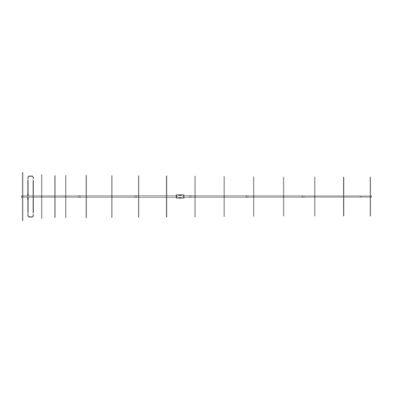
- Page 1 Cushcraft Amateur Radio Antennas LFA-2M16EL 16 Element Loop Feed Beam For 2 Meters INSTRUCTION MANUAL CAUTION: Read All Instructions Before Operating Equipment Cushcraft Amateur Radio Antennas 308 Industrial Park Road Starkville, MS 39759 USA Tel: 662-323-9538 Fax: 662-323-6551 VERSION 1A...
-
Page 2: General Description
GENERAL DESCRIPTION The LFA (Loop Fed Array) Low-Noise Yagi is very different from the traditional dipole fed Yagi in many ways with its primary benefit being unwanted noise rejection. The LFA has a rectangular shaped, full wave loop driven element that is laid flat on the boom between and in-line with the parasitic elements . Then there is the way in which the loop functions. - Page 3 BOOM IDENTIFICATION Here are the 7 boom sections with measurements displayed for the pre-drilled holes. The numbers on top are the distance in inches from the rear of the boom when it is correctly assembled. The numbers on bottom are the distance in inches from one side of the individual tube. These numbers are to verify correct location and orientation of each tube.
-
Page 4: Boom Assembly
BOOM ASSEMBLY Rear of Antenna 1-1/4 x .035 x 72 1-3/8 x .058 x 72 Place a #16 hose clamp over the tube before inserting next section 1-1/2 x .058 x 72 with 1-3/8 x .058 x 65 insert 1-3/8 x .058 x 72 1-1/4 x .058 x 72 1-1/8 x .058 x 72 1 x .058 x 16... - Page 5 Insert each tube 3 inches into the next using the marks you made. Try your best to align the holes in each tube. Tighten the hose clamps just enough so that the tubes do not move. Final alignment of the tubes will likely be needed later. Now would be a good time to support the boom on a couple of saw horses or something similar.
- Page 6 Long tube with saddle Rear of Antenna Element saddle and half washer. short tubes with insulator 8-32 x 2 8-32 nut #8 lock washer 7/16 X 14-1/2 7/16 X 14-1/2 Mount the insulator on the Boom at the second hole from the rear of the antenna using the 8-32 x 2 inch bolt.
- Page 7 Put one hose clamp over each end of each tube. Insert the loop ends into the 7/16 tubes. Don’t force them. Keep them straight as they go in. Leave them loose for tunning the SWR later. The tubes will have enough friction to stay without the hose clamps being tightened.
- Page 8 Element Bolt Sizes 2” 36-1/4 38-1/4 32-3/4 2-1/4” 32-7/8 25-1/4 2” 2” 2” 2” 2” 2-1/4” 2-1/4” 2” 2” 2-1/4” 2-1/4” 2-1/2 2” 2-1/2 2” Once you have all the elements on in the correct location, check the alignment of the elements on the boom sections.
- Page 9 Attach your coax to the feed loop using the remaining 8-32 nuts and lock washers. Make the distance of the exposed conductors as short as possible. Seal this connection using a appropriate sealant to prevent water from entering the coax. Wind a choke balun into the coax using a household cleaner or spray paint can.
-
Page 10: Boom Support
About 3 feet 12 element Antenna shown in vertical position for Illustration only. Boom support clamps are Tape coax to boom installed on the 1-1/4 inch end boom sections. and mast when mounted at its final loacation The antenna is now ready for mounting on your pole or tower. Route the coax along the boom and mast. -
Page 11: Parts List
part # Description PARTS LIST 190070 boom to mast 010401 u-bolt 564792 5/16 split washer 555747 5/16 hex nut 561177 1/4 lock washer 554099 1/4-20 hex nut 566344 FLAT WASHER 1/4 010404 UBOLT 745-3116S #16 hose clamp 745-3104S #4 hose clamp 455630 1-1/4 caplug 765-1000...
Need help?
Do you have a question about the LFA-2M16EL and is the answer not in the manual?
Questions and answers