Table of Contents
Advertisement
Quick Links
Advertisement
Table of Contents

Subscribe to Our Youtube Channel
Related Manuals for CUSHCRAFT MA160V


Summary of Contents for CUSHCRAFT MA160V
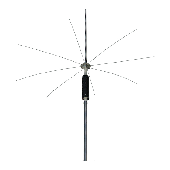
- Page 2 DX from an average-size house lot. A low launch angle and deep overhead null combine to pull in distant stations while rejecting local QRM. The MA160V features a heavy-duty high-Q copper loading coil plus a wide 100-inch diameter stainless capacitive hat for high efficiency, resiliency and 1500-Watt PEP power handling.
- Page 3 Assembly Instructions- MA160V Step 1: Using the items listed below, install aluminum tubes on base insulator. MA8040VBAB 12” x 1-3/8” OD aluminum base section (NS/2SH) MA8040VBAT 36” x 1-3/8” OD aluminum antenna section (2SH/4S) 126241 16” x 1-1/4” OD fiberglass base insulator 010231 1-3/4”...
- Page 4 Step-3: Assemble the capacitive-hat support ring. 194174 8-hole radial ring 196242 Upper radial-ring support bracket (do not confuse with set of 3 guy brackets) 010009 5/8” x 8-32 screw 360941 #10 aluminum spacer washer 011941 #8 lock washer 010011 8-32 nut [ ] Locate the two radial rings and place together so cupped grooves oppose.
- Page 5 Step-5: Complete assembly of the top resonator section. ---------- Radial ring assembly (set aside from Step-3) MA160VBI 1/2” OD x 35-7/8” resonator stub section (NS/2S) MA160VBJ 3/8” OD x 35-7/8” resonator stub section (NS/2S) MA160VBK 1/4” OD x 41” resonator stub section (solid rod) 055105 1/4”...
- Page 6 Step-7: Install the antenna guy supports. 030412 Large worm clamp 193631 Guy bracket 094259 Guy rope thimble MA160VGW Guy line, coil 100’ coil of Danscord-30D [ ] Find a large worm clamp and install loosely on tube BD 3” below the junction with tube BE. [ ] Find the three (3) guy brackets and slide them under the worm clamp band as shown (FIG-7A).
- Page 7 Also, ensure the top of the resonator will clear overhead branches when fully extended. The MA160V requires a stable ground support which must be constructed prior to raising the antenna. Any suitable post-style mount will work, but the antenna’s aluminum base is especially designed to slip inside readily available 1-1/2”...
- Page 8 [ ] Walk each guy line out to its anchor and tie in place as shown in FIG-12B. Important Warning: Never attempt to raise the MA160V without assistance. The un-guyed radiator is top-heavy and may become difficult to control without an extra pair of hands.
- Page 9 FIG-13: Feedline Connection Step-14: Install ground radials Basic System: This set-up works especially well for installing the MA160V within the confines of a typical residential house lot (FIG-14A). You’ll begin by installing 3 primary radials, then continue to add more—as needed—until achieving a feed resistance of approximately 50 Ohms (or minimum SWR).
- Page 10 Generally, for a loaded antenna like the MA160V, a dense ground system with a large number of shorter wires will perform better than a full-sized ¼-wave system with fewer radials. The layout described below should work well.
Need help?
Do you have a question about the MA160V and is the answer not in the manual?
Questions and answers