Table of Contents
Advertisement
Advertisement
Table of Contents

Subscribe to Our Youtube Channel
Related Manuals for Martin MX-1


Summary of Contents for Martin MX-1
- Page 1 MX-1 user manual...
- Page 2 ©1999 Martin Professional A/S, Denmark. All rights reserved. No part of this manual may be reproduced, in any form or by any means, without permission in writing from Martin Professional A/S, Denmark. Printed in Denmark. P/N 35000077, revision #990412-MA...
-
Page 3: Table Of Contents
To install a lamp in the MX-1 ........ -
Page 4: Introduction
76° of tilt, adjustable focus, a 16° beam angle, and a variety of control options. The MX-1 is not for household use. It is not for children: it presents risks of injury due to electric shock, burns, falls, high-intensity light, and fire. For safe operation,... -
Page 5: Unpacking
NEVER operate the fixture without all parts installed. • NEVER modify the fixture or install other than genuine Martin parts. U N P A C K I N G The packing material is carefully designed to protect the fixture during shipment - always use it to transport the fixture. -
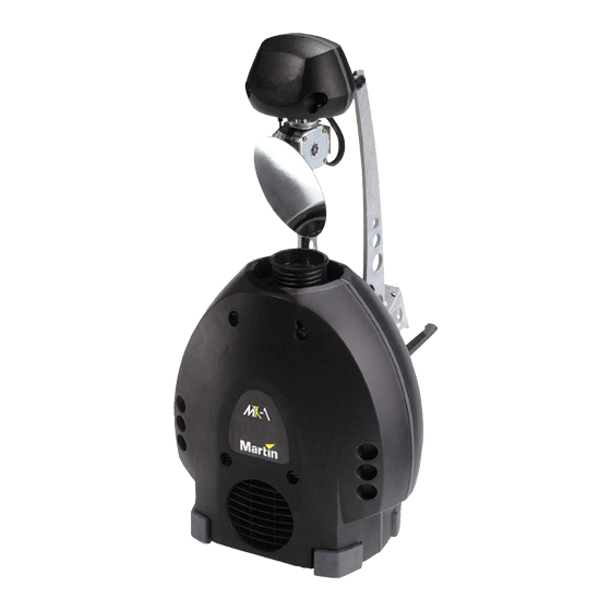
Page 6: Parts Key
5 pan/tilt arm safety cable holes mounting bracket air vents AC input & main fuse 10 DIP-switch 11 data output 12 data input 13 swivel locks 14 cooling fan Parts key MX-1 user manual... -
Page 7: Lamp Installation
AMP INSTALLATION The MX-1 uses a 24V, 250W ELC halogen lamp. Two models are available, an economical 300 hour lamp from Philips and a high-output 50 hour lamp from Osram. Installing any other lamp may damage the fixture. Allow the lamp to cool for at least 5 minutes before packing and moving the fixture. -
Page 8: Ac Power Connection
For safe operation, the fixture must be grounded (earthed). Important! Check voltage setting before applying power. Do not connect the MX-1 to an electrical dimmer system: doing so can damage the electronics. Before use verify that the fixture’s power supply is correctly tapped for the local AC voltage. -
Page 9: To Install A Plug On The Mains Lead
(earth), the brown wire to live, and the blue wire to neutral. The table below shows some pin identification schemes. Wire Marking Screw color brown live “L” yellow or brass blue neutral “N” silver yellow/green ground green MX-1 user manual AC power connection... -
Page 10: Installation
NSTALLATION The MX-1 can be fastened directly to a suitable surface or to a rigging clamp by means of its adjustable mounting bracket and it can be placed at an angle directly on the stage or floor using the mounting bracket as a floor stand. -
Page 11: Dip-Switch Settings
D M X A D D R E S S S E L E C T I O N If the MX-1 is to be used with a DMX protocol controller, then the DIP-switch must be set to the DMX control address. The address, also known as the start channel, is the first channel used to receive instructions from the controller. - Page 12 <6 458 48: 4;< 554 586 5;8 64: 67< 6;4 746 778 7:: 83< <7 459 48; 4<3 555 587 5;9 64; 683 6;5 747 779 7:; 843 <8 45: 48< 4<4 556 588 5;: 64< 684 6;6 748 77: 7:< 844 DIP-switch settings MX-1 user manual...
-
Page 13: Special Settings
Normal pan Enable special settings with pins 1 - 9 Enable DMX address with pins 1 - 9 1-channel mode on 1-channel mode off Reduced power / longer lamp life Full power / maximum intensity MX-1 user manual DIP-switch settings... -
Page 14: Data Connection
C O N N E C T I O N S The MX-1’s XLR data sockets are wired with pin 1 to ground, pin 2 to signal - (cold), and pin 3 to signal + (hot). This is the standard pin assignment for DMX devices. -
Page 15: To Connect The Data Link
A termination plug is simply an XLR connector with a 120 ohm, 0.25 W resistor soldered across pins 2 and 3. Male Female Termination Plug Termination Plug Male XLR Female XLR P/N 91613017 P/N 91613018 MX-1 user manual Data connection... -
Page 16: Operation
F U L L D M X O P E R A T I O N For DMX operation, the MX-1 must be connected to a DMX controller as described under “Data connection” on page 14 and its DIP-switch must be set to the control address as described on page 11. -
Page 17: Stand-Alone Operation
1 control signal on the data link. To connect unit s f or master / slave operati on 1 Connect the output of one MX-1 to the input of the next MX-1. 2 Connect additional MX-1s output to input. Up to 32 may be connected. -
Page 18: Basic Service
ASIC SERVICE The MX-1 requires simple routine maintenance. The maintenance schedule depends heavily on the operating environment; please consult a Martin service technician for recommendations. Any service procedure not described here should be referred to a qualified technician. Important! Excessive dust, grease, and smoke fluid buildup degrades performance and causes overheating and damage to the fixture that is not covered by the warranty. -
Page 19: To Clean The Fan And Air Vents
R E P L A C I N G F U S E S The MX-1 has 2 fuses. The main fuse holder is built in to the mains input socket. The secondary fuse is located on the printed circuit board. -
Page 20: Troubleshooting
Have the defective fixture serviced by a qualified technician. An effect fails to reset correctly. The effect requires mechanical Contact Martin technician for adjustment. service. No light. Lamp missing or blown Disconnect fixture and replace lamp. -
Page 21: Dmx Protocol
Up to down (127 = neutral) Pan/Tilt Speed 0 - 2 0 - 1 Tracking (speed function off) 3 - 255 2 - 100 Fast to slow See also “1-channel DMX operation” on page 16. MX-1 user manual DMX protocol... -
Page 22: Specifications
• MC-1 controller, EU ................90718000 • MC-1 controller, US................90718100 • Osram 24V/250W ELC 50 h halogen lamp..........97000104 • Philips 24V/250W ELC 300 h halogen lamp.......... 97000106 • G-clamp: ....................91602003 • Half-coupler clamp: ................91602005 Specifications MX-1 user manual...
Need help?
Do you have a question about the MX-1 and is the answer not in the manual?
Questions and answers