Table of Contents
Advertisement
Advertisement
Table of Contents

Subscribe to Our Youtube Channel
Related Manuals for Secutron MMX-2009-12NDS


Summary of Contents for Secutron MMX-2009-12NDS
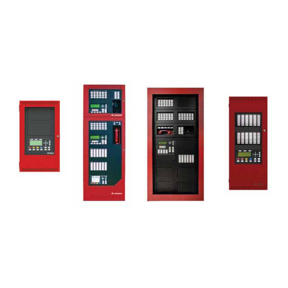
- Page 1 Intelligent Fire Alarm Network User Guide LT-893SEC Rev 1 May 2017...
-
Page 3: Table Of Contents
User Guide Table of Contents Introduction ..........................1 About this Manual ......................... 1 Front Panel Indicators, Controls, and Operation..............2 Front Panel Indicators and Control Locations (Model DSPL-420)........2 Front Panel Indicators and Control Locations (Model DSPL-420-16TZDS) ......3 Common Indicators ......................4 Common Controls......................... -
Page 4: Introduction
This user guide provides information on the Command Menu features of the MMX Network Fire Alarm and Audio system which includes MMX-2003-12NDS, MMX-2003-12NXTDS, MMX-2009-12NDS, and MMX-2017- 12NDS. Using the instructions provided in this manual, you will be able to: • Print reports •... -
Page 5: Front Panel Indicators, Controls, And Operation
Front Panel Indicators, Controls, and Operation Front Panel Indicators and Control Locations (Model DSPL-420) LCD Display - four lines, Cursor buttons, ENTER, MENU, 20 characters per line CANCEL, INFO Indicators for AC On, CPU Fault, and Ground Fault MCG Network Fire Control System - System Normal - May 04, 2016 12:00:00... -
Page 6: Front Panel Indicators And Control Locations (Model Dspl-420-16Tzds)
User Guide Front Panel Indicators and Control Locations (Model DSPL-420-16TZDS) Queue controls and 16 configurable indicators for Alarm, AC On bi-coloured zone CPU Fault Supervisory, Indicator indicators and 16 Indicator Trouble and Monitor trouble indicators Ground Fault Indicator LCD Display 4 lines 20 characters Menu... -
Page 7: Common Indicators
Front Panel Indicators, Controls, and Operation Common Indicators Buzzer The buzzer is activated by any of the following: • Fire alarm: steady • Supervisory alarm: fast flash rate • Trouble: trouble flash rate • Monitor: Configurable to sound at trouble flash rate If the buzzer turns ON in response to a non-latching trouble or supervisory, it will turn OFF if the condition causing it goes away and there is no other reason for it to be ON. -
Page 8: Common Controls
User Guide Signal Silence LED The Signal Silence LED flashes amber at the trouble flash rate SIGNAL FIRE after indicating circuits are silenced either by the Signal Silence SILENCE DRILL button, or by the Auto Signal Silence Timer. It turns OFF after the signals are re-sounded by a subsequent alarm. - Page 9 Front Panel Indicators, Controls, and Operation Queue Buttons Use the queue buttons to select a particular queue to review. • Use the Alarm Queue button to view all alarms. Pressing this button will show the latest alarm on the LCD display.
- Page 10 User Guide General Alarm Button Activation of the General Alarm button immediately sends the panel into general alarm. It will also re-activate the signals if they have been silenced during alarm. The general alarm condition remains active until the panel is reset.
-
Page 11: Troubleshooting
Reload the Configurator and/or reboot the system by powering it down and then (RAM) powering it up. This message displays if the system is overloaded and risks resetting itself. If Configuration Data Error this error should occur, please report it to Secutron’s Technical Support (FLASH) Department. -
Page 12: Start Up
User Guide Start Up Before start up, disconnect the network cable. When the system is plugged in and the batteries are connected, the front display will show: Initial system self checks in process... Let the system initialize for approximately one to two minutes. Download the configuration at each Node using a laptop computer and MMX Configurator. -
Page 13: Passcodes
Start Up Passcodes ENTER MENU MGC Net w or k Fi r e Al ar m Cont r ol Panel CANCEL Nor mal C o ndition INFO June 17, 2016 BLDG QUEUE QUEUE QUEUE QUEUE THESE BUTTONS REPRESENT THE CORRESPONDING NUMBER IN THE MENU MODE Pressing the Alarm Queue button represents the number 0... -
Page 14: Menu Mode
User Guide Menu Mode Press the button to activate the menu mode. The menu is broken down as follows: Menu Submenu Description How to Use Alarm Log View or print the Alarm Log. See page 13. Event Log View or print the Event Log. See page 13. -
Page 15: Front Panel Menu Operation
Front Panel Menu Operation 1. Reports Menu Use the Reports Menu to print the Alarm Log, Event Log, Current Levels, Verified Counts, Maintenance report, Current PWs, Obscuration, CO Maintenance report, and Battery Voltage. You can view on screen, or print directly to a printer connected to the panel, or to your laptop computer. - Page 16 User Guide Alarm Log The Alarm Log reports on all alarm events. Alarm events are listed in order of the most recent event to the earliest. The maximum number of recorded alarm log entries is 1000. Once the system reaches 1000 entries, any new entry will cause 500 of the oldest entries to be deleted.
- Page 17 Front Panel Menu Operation If a printer is connected to the panel, follow Step 2, below. Step 2: Print the Event Log •To print the Alarm Log to the printer, press when the cursor flashes beside “Printer”. - Report to - 1 Printer •To view the Alarm Log on the screen, press 2 Screen...
- Page 18 User Guide For example, if you select loop two, the screen will appear as follows: Loop 2 Address 001 Low Profile ION Det Current level: 846 Percent alarm: 0% • The first and second lines pinpoint the exact device. • The current level is a point of reference number that is helpful to our technicians. •...
- Page 19 Front Panel Menu Operation Step 4: If the display shows... No verified devices found..the display will return to the Reports Menu. If the display shows... •Press and hold to view the details. Loop 2 Address •Use to scroll the cursor through the Low Profile records.
- Page 20 User Guide Step 4: If the screen shows... No dirty devices found..the display will return to the Reports Menu. If the display shows... •Press and hold to view the details. Loop 2 Address 001 •Use to scroll the cursor through the Low Profile ION records.
- Page 21 Front Panel Menu Operation Step 3: Select Node and Loop number • Select a Node and Loop number by using to scroll through the numbers. • Select the Node by pressing -Select Node & Loop - Node: A L L •...
- Page 22 User Guide Step 3: Select Node and Loop number • Select a Node and Loop number by using to scroll through the numbers. • Select the Node by pressing -Select Node & Loop - Node: A L L • Select the loop number by pressing .
- Page 23 Front Panel Menu Operation Step 3: Select Node and Loop number • Select a Node and Loop number by using to scroll through the numbers. • Select the Node by pressing -Select Node & Loop - Node: A L L •...
-
Page 24: Bypass Menu
User Guide Step 3: Select Node • Select a Node by using to scroll -Select Node- Loop: A L L through the numbers, then when the correct Node number appears. Step 4: Pwr Src Report Battery Voltage The battery voltage will be displayed as per this Node 02 example. - Page 25 Front Panel Menu Operation Device/Circuit Bypass Use this option if you want to bypass or unbypass a device or circuit from the panel. Usually this is done when you need to add, remove, repair, or investigate a device or circuit. To unbypass the device or circuit, follow the same procedure for device/circuit bypass.
- Page 26 User Guide Unbypassing an active device/circuit When you unbypass a device or circuit that went into alarm while it was bypassed, you will see the following message: Warning: This output device is active. Do you really want to unbypass it? Y If you select “yes”...
- Page 27 Front Panel Menu Operation Step 2: Select a loop number 1. Use to select the Node and CPU -Select Input Zone- Node: 1 number. CPU: 1 2. Press to continue. Step 3: Bypass the loop 1. The systems now asks you whether or not you would like to bypass or unbypass the input zone.
-
Page 28: Walk Test Menu
User Guide 3. Walk Test Menu Use the Walk Test Menu when you want to test the devices in a system. Performing a walk test will place the system in trouble (non-latching). Note: Walk test records that are viewed on the screen will be stored in the event log. To enter the Walk Test Menu, you must be in the Command Menu. - Page 29 Front Panel Menu Operation Audible Test During this test, alarm activation of any input device will activate all signals for one half second. Trouble activation on any input device will activate all signals continuously for one second. If audio amplifier is configured for alarm and trouble events, it will sound words “Alarm”...
- Page 30 User Guide Step 5: Device View During the Walk Test During the Walk Test the device display will be as Nnn Lnn Adrnnnnnnnn shown. A: nnn T:nnn A = total number of alarm events for the device. Tag 1 Tag 2 T = total number of trouble events for the device.
- Page 31 Front Panel Menu Operation Step 4: Main Walk Test Screen During the Walk Test the display will be as shown. A = number of Walk Test alarm events OneMan T = number of Walk Test trouble events A:xxxx D:xxxx R:xxxx T:xxxx D:xxxx R:xxxx D = number of duplicate alarm and trouble events Press CANCEL to end...
- Page 32 User Guide Assisted Walk Test Assisted Walk Test must be configured using the Configurator. When the Assisted Walk Test is configured, the One Man Walk Test is replaced by the Assisted Walk Test. The Assisted Wall Test shall be in silent mode only. To enter the Walk Test Menu, you must be in the Command Menu.
- Page 33 Front Panel Menu Operation Step 5: Main Walk Test Screen During the Assisted Walk Test the display will be as shown. 1. Use to scroll the cursor through the devices. 1st Floor A = number of Walk Test alarm events A:xxxx D:xxxx R:xxxx T = number of Walk Test trouble eventss T:xxxx D:xxxx R:xxxx...
- Page 34 User Guide Step 4: Select the Screen option 1. Use to scroll the cursor through the - Walktest - menu. 1 Printer 2 Screen 2. Press to select an “Screen” option. Press to exit and return to the Command Menu. Step 5: Walk Test Report on Screen to scroll the cursor through the One Man(or 1st Floor)
- Page 35 Front Panel Menu Operation Step 4: Select the Printer option 1. Use to scroll the cursor through the - Walktest - menu to Printer. 1 Printer 2 Screen 2. Press to select Printer. Press to exit and return to the Command Menu. The following is an example of a printed Walk Test Report: --------------- - Walktest -...
-
Page 36: Alternate Menu Option #3: Manual Control Enable
User Guide Alternate Menu Option #3: Manual Control Enable Notes: •You will see this option in the Command Menu only if your system has been programmed for manual control. •This feature does not change after a system reset. This option provides security on the panel control buttons by requiring the user to enter a passcode or activate a key switch before a specific button will operate. -
Page 37: Day/Night Mode
Front Panel Menu Operation 4. Day/Night Mode Using the Configurator you can program day mode and night mode separately for different system sensitivity levels. Select the Day/Night mode option in the Command Menu if you would like to manually set the Day/Night mode. To enter the Day/Night Mode option, you must be in the Command Menu. -
Page 38: Set Time
User Guide 5. Set Time Note: Select this option if you would like to set the time only.You must use the Configurator to change the date. To enter the Set Time option, you must be in the Command Menu. To enter the Command Menu, press when the display is in normal mode. -
Page 39: Clear Event Log
Front Panel Menu Operation 6. Clear Event Log Select this option if you would like to clear the Alarm Log, Event Log, or all the logs. To enter the Clear Event Log option, you must be in the Command Menu. To enter the Command Menu, press when the display is in normal mode. -
Page 40: Clear Verification Counter
User Guide 7. Clear Verification Counter Select this option if you would like to clear the verification counter. To enter the Clear Verification Counter Option, you must be in the Command Menu. To enter the Command Menu, press when the display is in normal mode. Step 1: Select Clear Verification Counter 1. -
Page 41: Network Restart
Front Panel Menu Operation 8. Network Restart Use the Network Restart after downloading the MMX configuration. To select the Network Restart, you must be in the Comman Menu. To enter the Command Menu, press when the display is in normal mode. Step 1: Select Network Restart 1. -
Page 42: Choose Configuration
User Guide 10. Choose Configuration Select this option if you would like to select the configuration version to upload into the system. Step 1: Select Choose Configuration 1. Use to scroll the cursor to “Choose - Command Menu - 8 Network Restart Config”. -
Page 43: Paging Operation
Paging Operation QMP-5101N and QMP-5101NV Network Master Paging Indicators and Controls NP-6659 NP-6659 PAGE TO WARDEN EVAC PAGE PAGE TO ALL CALL ALERT MIC. A.C. ON ACTIVE PRE-TONE PAGE ACTIVE READY AMPLIFIER TROUBLE ALL CALL MINUS TROUBLE LAMP PAGE TEST CANCEL This section describes the controls and indicators on the QMP-5101N (shown in figure above) and QMP-5101NV Master Paging and QAZT-5302 Paging Selector Modules. -
Page 44: Qmp-5101N/V Pushbutton Controls
User Guide Page to Alert LED Illuminates steady green when the Page to Alert pushbutton is active. AC ON LED This green LED illuminates steadily to Indicate that AC power is present. Page Ready LED Illuminates steady green when the push-to-talk (PTT) on the microphone is depressed (active). Lamp Test LED This amber LED illuminates steadily to indicate that the Lamp Test has been activated. -
Page 45: Qazt-5302 Paging Selector Panel Leds
Paging Operation QAZT-5302 Paging Selector Panel Each QAZT-5302 annunciates and controls up to 24 paging zones. There is one button and two LEDs per zone. The lower Paging Paging Paging Paging Paging Paging amber LED indicates zone trouble. The upper green LED indicates whether that zone is Paging Paging... -
Page 46: Telephone Operation
User Guide Telephone Operation QMT-5302N/QMT-5302NV Master Firefighters’ Telephone Indicators and Controls CALL CONTROL CALL CONTROL TROUBLE INCOMING CALL DESELECT ALL ACTIVE This section describes the controls and indicators on the QMT-53021N (in figure above) and QMT-53021NV Master Telephone and QAZT-5302 Telephone Selector Modules. The QMT-53021NV is similar to the QMT- 53021N except the mounting is vertical. -
Page 47: Telephone Operation
Telephone Operation Telephone Operation 1. When any telephone zone rings (the local buzzer sounds intermittently, and the green zone LED and Incoming Call LED flash) press that zone's button (on the selector panel QAZT-5302) once to answer. Once any one zone has been answered, calls from any other zone will cause that zone's green LED and the Incoming Call LED at the master telephone to flash and the buzzer will sound. - Page 48 No part of this publication may be reproduced, transmitted, transcribed, stored in a retrieval system, or translated into any language or computer language, in any form by any means electronic, magnetic, optical, chemical, manual, or otherwise without the prior consent of Secutron. Canada U.S.A Technical Support...
Need help?
Do you have a question about the MMX-2009-12NDS and is the answer not in the manual?
Questions and answers