
Related Manuals for Eriez 1230


Summary of Contents for Eriez 1230
- Page 1 MMDG-1230-DIGITAL Installation, Operation and Maintenance Instructions Metal Detector MoDel 1230 Digital ERIEZ MAGNETICS HEADQUARTERS: 2200 ASBURY ROAD, ERIE, PA 16506–1402 U.S.A. WORLD AUTHORITY IN SEPARATION TECHNOLOGIES...
- Page 2 Careful attention to these requirements will assure the most efficient and dependable performance of this equipment. If there are any questions or comments about the manual, please call Eriez at 814-835-6000 for Model 1230 Metal Detector assistance. CAUTION Safety labels must be affixed to this product.
-
Page 3: Table Of Contents
Table of Contents ERIEZ METAL DETECToR MoDEL 1230 SAFETY WARNINGS ......................5 General ........................5 Installation ........................5 Connections ......................... 5 Long Term Storage....................... 5 GENERAL INFoRMATIoN ....................5 Standard Warranty ....................... 5 Installation Assistance ....................5 Technical/Application Assistance ................. 5 DESCRIPTIoN ........................ - Page 4 Table of Contents (continued) ERIEZ METAL DETECToR MoDEL 1230 Menu Tree (operator Level 1) ..................30 Menu Tree (operator Level 2) ..................34 Menu Tree (operator Level 3) ..................37 ERRoRS AND FAULT RECTIFICATIoN................44 Error Messages ......................44 Undefined Activation of Switching Outputs ..............46 APPENDIX A: CONTROL CONNECTION DIAGRAMS ....
-
Page 5: Eriez Metal Detector Model 1230
Eriez shall not be liable for any direct, indirect, consequential or incidental damages • Do not allow moisture to collect in the electronics from use, results of use or inability to use this product. -
Page 6: Description
SAFETY INFORMATION FOR OPERATORS induced current in the metal then induces a current in The Eriez 1230 control unit must be in perfect the receiver antenna. This technique provides optimum working order and used for the purpose for which it... -
Page 7: Electronic Enclosure
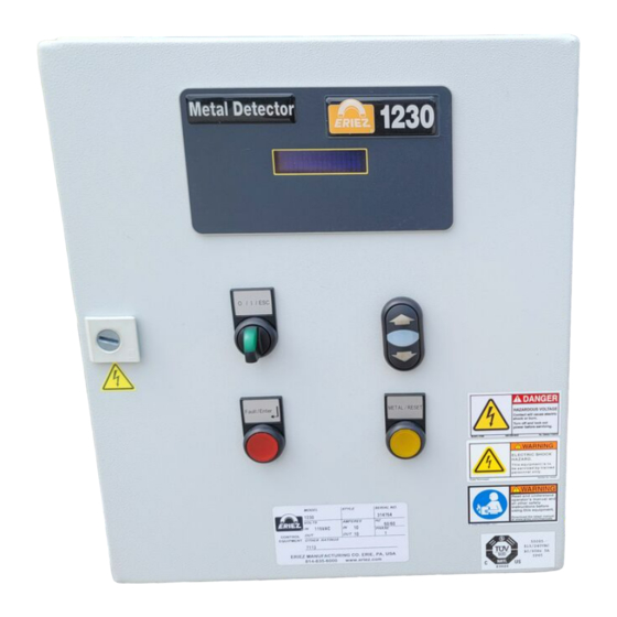
Detector. As standard, the Detector is housed in a steel NEMA 4 rated enclosure. Other enclosures are available as options: NEMA 4X (304 or 316SS available), NEMA 7/9. Figure 1 ERIEZ Metal Detector Model 1230... -
Page 8: Technical Data
Technical Data Name Eriez 1230 Control Unit Housing Sheet steel, Powder Coated Gray Weight 21 lbs (9.5 kg) Ambient Temp. -40°F to 149°F (-40ºC to +65°C) NEMA 4 standard ingress Protection other Ratings optional Operating Voltage 115 / 240VAC (±10%), 50/60 Hz, 5A Current Consumption 300MA/115V, 150MA/230V Typ. -
Page 9: Electronics Board
Electronics Board ST10 -5V -24V -24V -15V -15V -24V L100 JPM7 1 2 3 4 5 6 7 8 9 10 1 2 3 4 5 6 7 8 9 10 Main Board (rev.C) ERIEZ Metal Detector Model 1230... - Page 10 Connectors and “Mains” Mains Supply Terminals “Direct out” Potential free change over contact (SPST) “Fault” Potential free change over contact (SPST) “Timed out” Potential free change over contact (SPST) “Transmitter” Transmitter Coil 1-10: “Inputs” 11-20 “Input/output” “Receiver” Receiver Coil Ribbon Cable Connector Connector for control panel ST10 Connector...
-
Page 11: Signal Analyzer Board
Supply voltage -15V DIS/ (not used) Metal-Signal-oUT from signal analyzer Zero pulse Z Enable pulse EN (10) Sample Pulse S- (11) Sample Pulse S+ (12) Analyzer identification (+5V) Jumpers: Analyzer identification: Jumper must be closed ERIEZ Metal Detector Model 1230... -
Page 12: Search Coil Assembly
Search Coil Assembly Mounting Frame The mounting frame supports the antennas on trough The Search Coil Assembly includes receiver and slider bed conveyors. Special designs are available and transmitter antennas, mounting frame and to accommodate other types of material handling interconnecting cables. -
Page 13: Clip Detector
The clip detectors are labeled “Upstream” and “Downstream” to indicate the location they should be placed. Figure 4 Figure 5 ERIEZ Metal Detector Model 1230... -
Page 14: Spray Marking Device
Spray Marking Device (if applicable) The Spray Marking Device is a pressurized, solenoid activated liquid spray system which pinpoints the location of tramp metal to eliminate costly search and down time. Figure 6 Flag Drop Marker (if applicable) The Flag Drop Marker is a device which drops a tag or flag onto the belt which pinpoints the location of tramp metal to eliminate costly search and down time. -
Page 15: Idler Isolation Kit
Synchronization is used when two metal detectors are used within 100' of each other and are within a line of sight. Exception is when there is a metal wall or other metal structure between the two metal detectors to block the signals from the metal detectors. ERIEZ Metal Detector Model 1230... -
Page 16: Installation
Installation Position the entire search coil assembly so that the bottom coil (usually the receiver) is equally spaced between the two adjacent idler rollers. Use the receiver PLEASE READ THRoUGH CoMPLETELY BEFoRE or transmitter coil connector as the center line. Do not BEGINNING WoRK! center the 2"... - Page 17 Figure 10 ERIEZ Metal Detector Model 1230...
-
Page 18: Mounting - Search Coil Assembly
Mounting – Search Verify that the search coil assembly is square and all bolts installed are properly tightened. Coil Assembly Position the entire search coil assembly so the bottom Note the material flow direction arrows, match marks and receiver coil is equally spaced from the idler rollers on other identification on the Detector components before either side. - Page 19 Receiver Bracket Left Receiver Bracket Right Transmitter Bracket Left Transmitter Bracket Right Receiver Antenna (xx = coil length) Transmitter Antenna (xx = coil length 1380Hz) Roughing Guard (optional) Swing-Away Switch (optional) Figure 11 Frame Assembly Diagram ERIEZ Metal Detector Model 1230...
-
Page 20: Mounting - Main Control Enclosure
Do not run any power wiring in the same conduit or near the transmitter and receiver cables. Always discuss with Eriez before altering cable length. Always use original cables supplied with unit. Synchronization of several metal detection units: If several metal detectors are installed within 100' (30m) of each other, a shielded 2 core “twisted pair”... -
Page 21: Clip Detector
3/4" support pipe (provided) to Detector's performance because it will frequently be in a the conveyor frame. The pipe may be cut to the proper desensitized mode. Figure 14 ERIEZ Metal Detector Model 1230... -
Page 22: Dual Clip Detector
Dual Clip Detector Spray Marking Device (if applicable) (if applicable) Refer to the Control Connection Diagram Appendix A The Spray Marking Device is a pressurized, solenoid Figure A9, for hookup, and Figure 15 for placement. activated liquid spray system which pinpoints the location Idler roller type conveyor position the Up Stream Clip of tramp metal to eliminate costly search and down time. - Page 23 The spray solution can be purchased from Eriez or Mix the solution and pour it into the holding tank. supplied by the User. The recommended mixture is five Replace the cap. (5) fluid ounces of colorant, Chrome Yellow (or other...
-
Page 24: Flag Drop Marker
Figure 17 Positioning the spray assembly Flag Drop Marker Clamp in place now drill the a hole in the side of the C channel to secure the bottom of the upright and drill a (if applicable) couple of holes through the upright support and top of C channel and secure the support to the conveyor C channel. - Page 25 Figure 18 Mounting of the flag drop marker Figure 19 Positioning the flag marker ERIEZ Metal Detector Model 1230...
-
Page 26: Start-Up & Calibration
Start-Up & Calibration Operation General advice for operation Start-Up • To operate the Eriez 1230 Metal Detector use the UP, DOWN, ENTER ↵ and ESC keys. Before applying power to the system make sure that all of the connections are correct. -
Page 27: Metal Sensitivity Calibration
80 C2 signal not trip the detector. If the detector trips with the smaller analyzer the message >> SURgE << appears and metal then the sensitivity adjustment needs to be reduced. metal detection is switched off. ERIEZ Metal Detector Model 1230... -
Page 28: Clip Detector Calibration
Clip Detector Calibration displayed in the window. Using the up and down arrow enter the number 3080. Press up arrow until “3” (if applicable) is displayed press enter, an X will be over the three that was just entered and the cursor will have moved The clip detector can be set up two ways: one place to the left and a “0”... -
Page 29: Direct And Timed Out Setup
“enter”. Next press the down arrow until “reject del. time” is in the display, press “enter”. Set the delay before activation time by using the up and down arrow keys, set between 0 to 30 seconds, press “enter”. ERIEZ Metal Detector Model 1230... -
Page 30: Menu Tree (Operator Level 1)
Menu Tree (Operator Level 1) -
Page 31: Eriez Metal Detector Model
Pressing the ↵ button selects the submenu “Device information”. Further submenus are explained below. Logbook Pressing the key selects the submenu “Logbook”. Generally 2 screens (2 pages) are used for creating entries in the logbook. ERIEZ Metal Detector Model 1230... - Page 32 Example 1: Metal Alarm Screen 1: Message text for metal alarm: 001< Entry number, example no: 001 Metal Message text 22.02. 07:46 Date and time of event Press UP key to move to screen 2 Screen 2: information about message text: Information and tips relating to message text on screen 1 are shown here, 001<...
- Page 33 Max number of logbook entries: 100 entries (non-permanent memory is lost when powered down, network standard time: 1.1.2000 00:00:00) Software Version Press ↵ to select submenu “Software Version”. This displays the current software version. This displays the current software version. ↵ closes the screen. ERIEZ Metal Detector Model 1230...
-
Page 34: Menu Tree (Operator Level 2)
Menu Tree / Setting Menu (Operator Level 2) -
Page 35: Settings Menu
Reject delay can be adjusted between 0.00 seconds and 30.0 seconds using the UP / DOWN keys. Press ↵ to confirm the set value. Note: This submenu affects only the relay output >> Timed Out <<. ERIEZ Metal Detector Model 1230... - Page 36 Timed Out Pressing the ↵ key selects the submenu “Timed out”. This position determines whether the metal outputs should be reset manually or automatically (after preset reject duration). Use the UP / DOWN keys to select the type of RESET: “AUTO” or “MANUAL”.
-
Page 37: Menu Tree (Operator Level 3)
Menu tree / System functions (Operator level 3) ERIEZ Metal Detector Model 1230... - Page 38 Continued from previous page...
- Page 39 Clip mode DUAL means that two clip detectors are available, typically used for variable speed belts or belts that start/stop frequently the first clip detector switches the system to clip mode (lower sensitivity), the second clip detector returns the sensitivity to normal system operation. ERIEZ Metal Detector Model 1230...
- Page 40 Clip Duration Press ↵ to select submenu “Clip Duration”. A value between 0 and 30 seconds can be set using the UP / DOWN keys. Use the ↵ key to confirm the setting. Note: This submenu will only be displayed in SINGLE clip mode. Clip duration means: The system is operated with the clip sensitivity setting for the clip duration which is set here.
- Page 41 This menu “Re-learn or accept” is displayed after the received values are shown. Press the ESC key to start the learning process again (Menu selection: >> Waiting for clip <<). Press ↵ to accept the learned values. ERIEZ Metal Detector Model 1230...
- Page 42 Password / Code setting Press ↵ to select submenu “Code Settings”. A four character password code to password protect the settings screen can be entered here. Use the UP / DOWN keys to select the numbers. Pressing ↵ confirms the selected letter, number or symbol and the cursor then moves to the next position.
- Page 43 Use the ↵ key to confirm the setting. Display Temperature Press ↵ to select the submenu “Display temperature”. The temperature shown refers to temperature inside the housing or on the display. Necessary for adjusting automatic display contrast (only used for LCD screen) ERIEZ Metal Detector Model 1230...
-
Page 44: Errors And Fault Rectification
Errors and Fault Rectification if you have any questions, please call and have the serial number available! Error Messages When an error message is detected the red “Fault” LED on the operator panel flashes and the fault relay trips out. The appropriate error will be shown on the screen. - Page 45 The sensor must deliver a signal for 60 seconds in order to activate the error message Error Message Possible Causes Action Transmitter coil folded Fold back transmitter coil, back > Swing Away < check sensor and measure sensor defective sensor signal with voltmeter ERIEZ Metal Detector Model 1230...
-
Page 46: Undefined Activation Of Switching Outputs
Monitoring of signal analyzer This message is displayed when the signal analyzer plugged into the main board is different to that set up in the menu Error Message Possible Causes Action Signal analyzer plugged into Change signal analyzer in the main board is not the same as main board or select different selected in menu... -
Page 47: Appendix A: Control Connection Diagrams
APPENDIX A Control Connection Diagrams DANGER All electrical connections should be made with the power off! WARNING Please double check all connections before applying power to avoid potential damage to the electronics. ERIEZ Metal Detector Model 1230... -
Page 48: Appendix A: Wiring Diagram
Appendix A: Wiring Diagram The first drawing shows the electronics as they are wired from the factory. Most wiring will be done to the terminal block TB1. This includes input power, alarms, and interfacing with your plant control system. The antennas, clip detector and swing away switch are wired directly to the appropriate connections on the main board (bypassing TB1) For every numbered terminal position on TB1 there are 4 terminals. - Page 49 ERIEZ Metal Detector Model 1230...
- Page 50 Figure A1 Enclosure Diagram - Factoring Wiring...
-
Page 51: Input Power To The Detector
5. Insert the Neutral line into the “N” socket on terminal block TB1. 6. Attach the ground wire lug to the provided PE ground point in the lower left corner of the mounting plate. ERIEZ Metal Detector Model 1230... - Page 52 Figure A3 Receiver Antenna Connections...
-
Page 53: Receiver Preparations
The image below shows a representation of the cutaway with the connector build up using a clear shielded cable for reference. ERIEZ Metal Detector Model 1230... - Page 54 Figure A4 Transmitter Antenna Connections...
-
Page 55: Transmitter Preparations
9. Remove the insulation and prepare the black and clear The image below shows a representation of the cutaway jacketed wires for installation to the transmitter plug. with the connector build up using a clear shielded cable for reference. ERIEZ Metal Detector Model 1230... -
Page 56: Metal Detected - Direct Output Connection
Figure A5 Metal Detected - Direct Output Connection Metal Detected - Direct Output Connection Terminal 8 - Normally open Contact (Closes when metal is detected) Terminal 9 - Direct output Center Pin Terminal 10 - Normally Closed Contact (opens when metal is detected) This relay (when active via the software) will switch when metal is detected and will remain switched until the metal detector is reset either by turning the reset knob on the door, or closing a connection between the remote reset terminals (TB 1 –... -
Page 57: Metal Detected - Timed Output Connection
0.1sec increments. The timed output is commonly used for marking devices and automatic metal diverter systems. Refer to the menu tree on page 30 of this manual for how to program the timed output. ERIEZ Metal Detector Model 1230... -
Page 58: Fault Output
Figure A7 Metal Detected - Direct Output Connection Fault Output Terminal 11 - Normally open Terminal is closed when detector is operating (Opens when detector is powered off or a fault condition exists) Terminal 12 - Fault output Center Terminal 13 - Normally Closed Terminal is open when detector is operating (Closes when detector is powered off or a fault condition exists) -
Page 59: Single Clip Detector Connection
Single Clip Detector Connection Red Wire - Input Terminal 1 White Wire - Input Terminal 2 Black & Shield - Input Terminal 3 Figure A8 Single Clip Detector Connection ERIEZ Metal Detector Model 1230... -
Page 60: Dual Clip Detector Connection
Dual Clip Detector Connection Upstream Clip Detector Red Wire - Input Terminal 1 White Wire - Input Terminal 2 Black & Shield - Input Terminal 3 Downstream Clip Detector Red Wire - Input Terminal 4 White Wire - Input Terminal 5 Black &... -
Page 61: 24Vdc Spray Marker
(You should see a factory installed jumper wire between terminals 15 and 20 on TB1. Terminal 19 should be factory connected to Input/Output Terminal 19 on the main board. Terminal 20 should be factory connected to Input/Output Terminal 17 on the main board) ERIEZ Metal Detector Model 1230... -
Page 62: Flag Drop Marker
NoTE: DISCoNNECT FLAG DRoP MARKER CABLE CoNNECTIoNS AT THE MAINS AND TIMED oUT CoNNECToRS PRIoR To PERFoRMING ANY WoRK INSIDE FLAG DRoP MARKER ENCLoSURE. FLAG DRoP MARKER CoNNECTIoN CoLoR SCREW TYPE BLACK WHITE N (5) GREEN BLUE RED/BLK oRANGE Figure A11 Flag Drop Marker Connection... -
Page 63: 24Vdc Panel Mount Alarm Horn And/Or Light
BRoWN BLUE 9 & 19 ALARM LIGHT AND/oR HoRN WILL BE PRE-WIRED FoR PANEL MoUNTED LIGHTS/HoRNS. ERIEZ DoES NoT SUPPLY CABLE FoR REMoTE MoUNTING AS STANDARD 18ga. 2 CoNDUCToR CABLE SHoULD BE USED. FoLLoW INSTRUCTIoNS WITH LIGHT/HoRN FoR WIRING. Figure A12... - Page 64 BLACK WHITE BRoWN BLUE 9 & 19 ERIEZ DoES NoT SUPPLY CABLE FoR REMoTE MoUNTED AS STANDARD 18ga. 2 CoNDUCToR CABLE SHoULD BE USED, MAX LENGTH 250ft (76m). FoLLoW INSTRUCTIoNS WITH LIGHT/HoRN FoR WIRING. Figure A13 24VDC Pole Mounted Alarm Light and/or Horn Connection...
-
Page 65: 115 Or 220Vac Pole Mount Alarm Horn And/Or Light
SCREW TYPE BLACK WHITE ALARM LIGHT AND/oR HoRN WILL BE PRE-WIRED FoR PANEL MoUNTED LIGHTS/HoRNS. ERIEZ DoES NoT SUPPLY CABLE FoR REMoTE MoUNTING AS STANDARD 18ga. 2 CoNDUCToR CABLE SHoULD BE USED. FoLLoW INSTRUCTIoNS WITH LIGHT/HoRN FoR WIRING. Figure A14... -
Page 66: Voltage Regulator
Figure A15 Voltage Regulator Connection Voltage Regulator Voltage Regulator Terminal 1 - Input Power 115VAC or 220VAC Voltage Regulator Terminal 2 - Input Neutral or 220VAC Voltage Regulator Terminal 3 - Ground (Earth) (Input and output) Voltage Regulator Terminal 4 - output Neutral or 220VAC Voltage Regulator Terminal 5 - output 115VAC or 220VAC... -
Page 67: Swing Away Switch Connection
Swing Away Switch Connection (High Pile Detector) White Wire - Terminal 9 Black and Shield Wire - Terminal 10 Figure A16 Swing Away Switch Connection ERIEZ Metal Detector Model 1230... -
Page 68: Remote Reset Connection
Figure A17 Remote Reset Connection Remote Reset Connection Red Wire - Terminal 17 orange Wire - Terminal 18 The remote reset can be used to remotely reset the metal detector after metal has been detected. Do not apply voltage to these terminals! Dry contact only! -
Page 69: Synchronizing 2 Detectors
- Connects to Terminal 12 Sync In- on Detector 2 (Slave) If more than 2 detectors need to by synchronized, they can be daisy-chained, so Detector 2 would be master for Detector 3 and so on Wire Descriptions and Sizes: See page 20 ERIEZ Metal Detector Model 1230... -
Page 70: Appendix B: Service, Parts, Repairs
RGA number. Simply fill out the form and fax it to Eriez, or call Eriez with all the information required and you will be issued an RGA number. -
Page 71: Replacing Electronic Boards
Replacing Electronic Boards The Eriez 1230 control unit consists of 3 electronic boards, Evaluation electronics, the Signal analyzer board and the Display board (see next page). Signal Analyzer Evaluation Electronics ERIEZ Metal Detector Model 1230... -
Page 72: Replacing The Data Memory
The “Eriez 1230” Evaluation Electronics are equipped with a memory module which contains all the equipment settings and product data. if this memory board is transferred to the new Evaluation Electronics board the original settings will be transferred to the new board. -
Page 73: Replacing The Main Electronics Module
L. Secure the ground (earth) wire to the back plate using the nut the nut holding the ground (earth) wire to the back plate. M. Reconnect the ribbon cable to the socket on the Evaluation Electronics module being careful not to bend any pins ERIEZ Metal Detector Model 1230... -
Page 74: Spare Parts, Servicing
Spare Parts, Servicing Please state type of equipment and serial number when contacting us. Spare Parts Drawing Spare Parts List item No. Part Remarks Drawing No. Enclosure Mild Steel (other options avail.) on/off/Esc - 3 way switch w/ legend Up/Down Arrow Buttons Metal Light / Reset Button (Yellow) w/ legend Fault / Enter Button (Red) w/ legend Display Electronics Module (VFD) -
Page 75: Frame Assembly
Transmitter Antenna (xx = coil length 1380Hz) Roughing Guard (optional) Swing-Away Switch (optional) Eriez and Eriez Magnetics are registered trademarks of Eriez Manufacturing Co, Erie, PA ©2016 Eriez Magnetics All Rights Reserved World Authority in Separation Technologies ...
Need help?
Do you have a question about the 1230 and is the answer not in the manual?
Questions and answers