Table of Contents
Advertisement
Advertisement
Table of Contents

Related Manuals for Eriez E-Z TEC IV


Summary of Contents for Eriez E-Z TEC IV
- Page 1 Installation, Operation and Maintenance Instructions ® ® E-Z Tec Metal Detectors Models IV & V ERIEZ MAGNETICS HEADQUARTERS: 2200 ASBURY ROAD, P.O. BOX 10608, ERIE, PA 16514–0608 U.S.A. WORLD AUTHORITY IN ADVANCED TECHNOLOGY FOR MAGNETIC, VIBRATORY and METAL DETECTION APPLICATIONS...
- Page 2 Introduction This manual details the proper steps for installing the Eriez ® E-Z Tec Model IV and V Metal Detectors. Careful attention to these Installation Requirements will assure the most efficient and dependable performance of this equipment. If there are any questions or comments about the manual, ®...
- Page 3 LIFT ONLY ON DETECTOR If handling with eye-bolts threaded into pre- HOUSING SERVICES THAT INCLUDE tapped holes supplied by Eriez: SUPPORTING “FEET” OR TAPPED LUGS, as supplied by Eriez. a. Make sure that eye-bolts are strong enough...
-
Page 4: Table Of Contents
Table of Contents Table of Contents ERIEZ E-Z TEC METAL DETECTORS - MODELS IV AND V GENERAL ......................12 PRINCIPLE OF OPERATION ................12 SPECIFICATIONS ....................13 DETECT MODES ....................15 Mode 1 ......................15 Mode 2 ......................15 INSTALLATION CAUTION!! ................16 MECHANICAL INSTALLATION ................ - Page 5 Table of Contents (cont.) Inputs ......................22 Tachometer Input (TACH) ................ 22 Proximity Switch (PROX SW) ..............22 Reject Confirmation (REJ CON) .............. 22 Reject Reset (REJ RESET) ..............23 ® Host Computer Port (MPC only) ............23 Printer Port (MPC only) ................23 Conduit ......................
- Page 6 Table of Contents (cont.) Analog Output Controls (cont.) ..............26 Window LED .................... 26 Index In LED .................... 26 Confirm LED .................... 26 Clock LED ....................27 Detect LED ....................27 Analog Circuit Board Switch Programming ........... 27 SW1-1 ..................... 27 SW1-2 .....................
- Page 7 Table of Contents (cont.) Controlling the MPC Display ................. 32 Travel Between Menus ................32 Changing Variables ................. 32 Detailed MPC Menu Description ..............32 Power Up Display ..................32 Monitor Display ..................32 Change Product Menu ................33 Identification Display ................33 Main Menu ....................
- Page 8 Table of Contents (cont.) Options ....................39 Buzzer ....................39 Setup Communication ............... 39 Setup Printer ..................39 Factory....................39 Set Time and Date ................39 Update Passwords ................39 Print Options .................... 39 Diagnostics ....................39 Troubleshooting ................. 39 Self-Check ..................
- Page 9 Table of Contents (cont.) MAINTENANCE ....................54 SPARE PARTS ....................54 Analog Unit Spare Parts ................54 MPC Unit Spare Parts ................... 55 FIGURES ......................56 APPENDIX A - PRINTER OPERATION (MPC ONLY) ........77 Introduction ....................77 General Description ..................77 Detailed Description ..................
- Page 10 Table of Contents (cont.) APPENDIX C - VARIABLE REJECT UNITS ............83 Introduction ....................83 Mechanical ....................83 Electrical ......................84 APPENDIX D - SLIM TEC SINGLE SURFACE UNITS ........86 Introduction ....................86 Mechanical ....................86 Electrical ......................87 APPENDIX E - SLIM TEC APERTURE UNITS ...........
-
Page 11: General
This manual covers both the analog and MPC Detectors are state of the art electronic devices versions of the E-Z Tec IV and V. Much of the for detecting fine particles of metal in non-metallic discussion herein is relevant to either version. -
Page 12: Principle Of Operation
Principle of Operation The E-Z Tec IV/V Metal Detector uses a that is amplified and manipulated to extract the differential transformer to detect pieces of metal. amplitude and phase angle with respect to the Three coils encircle the detection aperture. The oscillator input signal. -
Page 13: Specifications
Specifications POWER SOURCE REQUIREMENTS REJECT CONFIRMATION INPUT (TWO RANGES) Voltage 105 to 125 VAC 50 to 60 Hz. Logic 0 - 0.0 VDC to 0.9 VDC. Max. surges of 150 V RMS for a period Logic 1 - 3.15 to 50 VDC. of 2 seconds. - Page 14 Specifications (cont.) ENCLOSURE RATING REJECT COUNTER (MPC ONLY) NEMA-4X/IP66. The MPC stores a running total of the number of times the Direct Reject output has cycled. PRODUCT VELOCITY This normally provides a very close approxi- The metal detector can be adjusted to scan mation of the total number of detections while products traveling from approximately 2 ft./min.
-
Page 15: Detect Modes
Detect Modes E-Z Tec IV and V metal detectors can operate in either In general, Mode 2 detection may be somewhat of two detect modes. The most appropriate mode for less sensitive than Mode 1 detection. Also Mode 2 a given application depends largely upon... -
Page 16: Installation Caution
Installation Caution!! E-Z Tec IV and V metal detectors have been to be extremely sensitive to vibration and/or will manufactured to very stringent quality control false trip (generate a false reject signal) when standards to ensure that they will provide years the conveyor starts and stops. -
Page 17: Metal Free Area
Mechanical Installation (cont.) supporting the pulleys and idlers represent METAL FREE AREA potential switches. As they turn, the bearings The metal detector monitors an electromagnetic make and break contact with their respective field to detect metal. This field is predominantly races through the lubricant within. -
Page 18: Permanent Loops
Mechanical Installation (cont.) Both insulating methods are reliable. However, it Figure 11 shows the modified conveyor frame. takes only a small metal shaving or burr to cut Note the potential switches no longer exist and through and short-circuit the insulators. For this the only currents in the conveyor frame are reason the insulation should be tested with an running through welded, permanent connections. -
Page 19: Belt Splices
Mechanical Installation (cont.) BELT SPLICES CONVEYOR SLIDER BED The metal detector sensing head cannot be The conveyor belt must be supported as it travels disassembled to be fitted around the conveyor through the metal detector. This task is performed belt. For this reason the conveyor must be by a slider bed, which must be capable of holding designed to return the belt through the aperture, the belt off the aperture liner even when fully loaded. -
Page 20: Electrical Installation
Electrical Installation INTRODUCTION CAUTION: Be careful to distinguish between the input All electrical connections are intended to be made voltage selection switch and the power (off/on) within the NEMA-4X power supply enclosure. switch. Both are located in the lower left corner Figure 14 shows the enclosure and the electrical of the power supply circuit board. -
Page 21: Relays
AC SSR RELAYS The AC SSR is a solid state relay suitable for The E-Z Tec IV and V provide three standard and switching AC loads only. It functions in parallel two optional relays as follows: with the Timed Relay described above. The relay... -
Page 22: Relay Notes
Electrical Installation (cont.) RELAY NOTES which is capable of precisely locating the package. As shipped, none of the relays source power. If The electrical specifications are as follows: switched AC power is needed it must be supplied to Voltage the appropriate relay through a jumper, such as from Logic 0 - 0.0 VDC to 0.9 VDC one of the L1 or L2 terminals or from an external Logic 1 - 3.15 to 50 VDC... -
Page 23: Reject Reset (Rej Reset)
The use of metal conduit will provide necessary power. If the fault cannot be located, con- shielding for the wires within; however, metal conduit tact Eriez Magnetics for assistance. also represents a potential ground path. Metallic conduit or airlines must be electrically insulated d. -
Page 24: Initial Test (Mpc Unit)
MONITOR display should ap- power. If the fault cannot be located, con- pear on the LCD screen showing time, date, tact Eriez Magnetics for assistance. SENSITIVITY ##, and PHASE ##. d. Close and latch the power supply enclo- sure door. -
Page 25: Analog Controls And Displays
Analog Controls and Displays ANALOG CONTROL PANEL ANALOG OUTPUT CONTROLS Figure 15 shows the location of the various front Figure 16 illustrates the output control panel of panel controls and indicators on the E-Z Tec the E-Z Tec Version IV and V analog metal Version IV and V analog unit. -
Page 26: Analog Output Controls (Cont.)
Analog Controls and Displays (cont.) PROGRAMMING SWITCHES illuminates as soon as there is no metal being These switches are located in the power supply detected and direct relay output has returned to housing of the analog metal detector. They are its normal state. -
Page 27: Clock Led
Analog Controls and Displays (cont.) CLOCK LED SW1-9 The CLOCK LED is used to show the rate at which When this switch is set to the UP position the the timer for the timed relay is operating. When the DIRECT RELAY will not reset after a reject until a internal clock is selected with SW2-3 the CLOCK signal is received at the REJ RESET input. -
Page 28: Sw2-2
Analog Controls and Displays (cont.) ad ju s tm en t ra ng e of 0 .3 0 s e co n ds to 5 0 This jumper is to set up the metal detector seconds. When JP2 is OFF (open) the TRAVEL when a proximity sensor is used. -
Page 29: Switch Charts
Controls and Displays (cont.) Switch Chart B Output Board PSOPT-1 SWITCHES SW1-3 THROUGH SW1-8 U = UP D = DOWN Shift Shift Switch SW1- Switch SW1- Register Register Length Length ®... -
Page 30: Mpc Controls And Displays
MPC CONTROL PANEL FLOWCHART Figure 19 is a flowchart representing the structure of Figure 18 illustrates the E-Z Tec IV and V MPC the portion of the MPC software which communicates control panel. The panel consists of a 22 segment with the operator. -
Page 31: Reject Reports
OPTIONS DETECT / REJECT DISPLAY Some metal detector adjustments do not change Each E-Z TEC IV and V MPC has two separate between products. The OPTIONS section of the reject timers which run in parallel. They are referred program is used to set these parameters. These to as Direct Reject and Timed Reject. -
Page 32: Controlling The Mpc Display
This display appears at power up for approximately of one of the listings. Two soft keys labeled “Se- 10 seconds. It provides Eriez Magnetics’ address lect Up” and “Select Down” are used to position and telephone numbers. -
Page 33: Change Product Menu
Consultation with to move the blinking cursor to the item to be Eriez is recommended. The factory setting appears adjusted. The INCR and DECR keys are used to on the Individual Unit Specification Sheet supplied increase or decrease the numerical value of the with the metal detector. -
Page 34: Configure Rejects
This menu controls settings for Direct Reject, Timed Timed Reject, Index Device is not Used (Fig. 27) Reject, and Detection on Powerup. Each E-Z TEC IV In the case where an index device is not used, and V MPC has two separate reject timers which run the following controls are relevant: in parallel, Direct Reject and Timed Reject. -
Page 35: Timed Reject, Index Device Used
MPC Controls and Displays (cont.) A tachometer must be used to monitor the con- If reject confirmation is needed, set the variable veyor speed and provide this information to the to “YES”; otherwise set it to “NO”. More informa- MPC. If a tachometer is used the “TACH IN- tion on function of this variable is available in the PUT?”... -
Page 36: Direct Reject
MPC Controls and Displays (cont.) Space Between Prod? Make sure the new Product Description is This variable is adjusted to indicate whether correct and press EXIT. The new description there is always space between adjacent will be permanently entered into memory (until products. -
Page 37: Erase All Reports
MPC Controls and Displays (cont.) NOTE: When a single piece of metal passes The three most recent detections are displayed through the metal detector, a dual polarity signal is when entering the Reject Reports menu. Other produced. If the metal passes through the unit detections can be reviewed using the SELECT slowly enough, a reject report may be generated UP / DOWN keys. -
Page 38: Reject Confirmation Fault
MPC Controls and Displays (cont.) Reject Confirmation Fault of an eventual failure. Thus, Eriez Magnetics If a Reject (Confirmation) Fault is listed, it means should be consulted to aid in determining the a Timed Reject has occurred and the MPC did cause of and remedy for the Balance Fault. -
Page 39: Options
MPC Controls and Displays (cont.) OPTIONS (FIGURE 35) Update Passwords (Figure 39) This menu contains adjustments which are rarely The password hierarchy is three level, in changed. increasing order: OPERATOR, SUPERVISOR, and ENGINEER. All can be changed as follows: Buzzer The MPC sounds a buzzer when a detection Align the cursor to PASSWORDS in the OP- occurs or when any key is pressed. -
Page 40: Self-Check
MPC Controls and Displays (cont.) Self-Check (Figure 43) Test Now The Self Check feature is used to monitor the main The Self Check test can be initiated manu- electronic circuits responsible for detecting metal and ally using this command. Move the cursor to to alert the operator if a failure is detected. -
Page 41: Calibration Check
Test cycle can be run over again throughout the manual, or contact Eriez for assistance. rest of the day; for example, at the beginning of each shift. This is achieved by setting the “Shift If the above procedure is not finished before the time”... -
Page 42: Configuring Analog Metal Detector
Configuring Analog Metal Detector Please read the Introduction to the Control PHASING OUT THE PRODUCT Panels and Displays section prior to attempting EFFECT ANALOG UNITS to adjust the metal detector. Some products are conductive or magnetic in All installation procedures must be complete nature and can produce a signal when passing before configuring the metal detector. -
Page 43: Reject Adjustment Analog Units
Configuring Analog Metal Detector (cont.) As the product enters the aperture, note the REJECT ADJUSTMENT ANALOG INITIAL DEFLECTION of the Monitor (right or UNITS left) and record it along with the Phase control Each E-Z Tec Version IV and V analog metal detector setting. -
Page 44: Timed Reject
Configuring Analog Metal Detector (cont.) Conversely, if you prefer to manually reset the reject nated product is rejected, repass the item(s), device after each rejection, you will set SW1-9 UP repeating this step a number of times until (a) for manual reset of a Direct Reject, and you can set you are convinced that contaminated product the Direct Reject Time to its minimum setting with will be rejected reliably at this Direct Reject time... -
Page 45: Timed Reject, Index Device Not Used
If product changes often, element of the reject device. If this time is an E-Z Tec IV or V MPC Metal Detector, with less than about 6 sec, disconnect the pins the ability to store multiple reject settings, may of Jumper JP2;... -
Page 46: Timed Reject, Index Device Used
Configuring Analog Metal Detector (cont.) of JP2. (If the travel time is greater than dex Device Used” below). If an index device is about 50 seconds, an additional delay de- not to be used, follow the procedure of step vice, beyond that provided in the metal de- (3) above, with the following differences: tector, may be required to activate the re- a. - Page 47 Configuring Analog Metal Detector (cont.) Trip the Proximity Device so that it constantly If there is always space between products (for sends the metal detector a signal indicating that example always space between individual product is being detected. This may be simple; boxes of sugar that the proximity switch will for example, if a photo eye is being used, the always detect), set the Jumper JP1 to OFF...
-
Page 48: Configuring Mpc Metal Detector
Configuring MPC Metal Detector MPC GENERAL OPTION SETUP probably need to be adjusted also. Consult with Eriez Magnetics for guidance. The entries of the OPTIONS Menu contain variables which rarely, if ever, need resetting after initial Adjust SENSITIVITY to 99. - Page 49 Configuring MPC Metal Detector (cont.) or standing vertically. For this reason the se- Manual PHASE Adjustment lected test sample should be spherical if pos- Some products are conductive or magnetic in sible. Otherwise, test the sample in all possible nature and can produce a signal when pass- orientations to account for orientation effect.
- Page 50 Configuring MPC Metal Detector (cont.) Throughout the following adjustment procedure, The phase adjustment is now complete. always be sure to pass the product through the Please refer back to Step 8 to adjust the aperture in the same direction. Also, the sample sensitivity.
-
Page 51: Mpc Reject Adjustment
Configuring MPC Metal Detector (cont.) e. Repeat step (d) until the MPC responds with needed to reject the metal reliably. This will keep “AUTO PHASE COMPLETE...”. the amount of rejected product to a minimum. f. Press EXIT to return to the PRODUCT If Auto Reset? is set to YES, the reject will reset SETUP menu. -
Page 52: Timed Reject, Index Device Used
Configuring MPC Metal Detector (cont.) Use the smallest size tramp metal which will Use the smallest size tramp metal which will produce reliable detections. Large pieces of produce reliable detections. Large pieces of tramp metal may cause the detection signal to tramp metal may cause the detection signal to be extended which will give the illusion of re- be extended which will give the illusion of re-... -
Page 53: Obtaining Mpc Reject Reports
Configuring MPC Metal Detector (cont.) If there is always space between products OBTAINING MPC REJECT REPORTS (for example always space between indi- Reject Reports are available from three sources: vidual boxes of sugar which the proximity switch will always detect), set the SPACE The reject reports may be reviewed on the MPC BET PROD? variable to YES. -
Page 54: Maintenance
Spare Parts The following are lists of recommended spare parts When ordering replacement parts include the part for the E-Z Tec IV and E-Z Tec V Metal Detector. description, part number, and serial number of the metal detector. Analog Unit Spare Parts... -
Page 55: Mpc Unit Spare Parts
MPC Version V Control Assembly w/PCB & Door 815529 Board PC MPCPS, Power Supply PCB Assembled 814861 Board PC AMOS-1, Amplifier & Oscillator (E-Z Tec IV only) 816237 Board PC AMOS-2, Amplifier & Oscillator (E-Z Tec V only) * Please specify cable length. -
Page 56: Figures
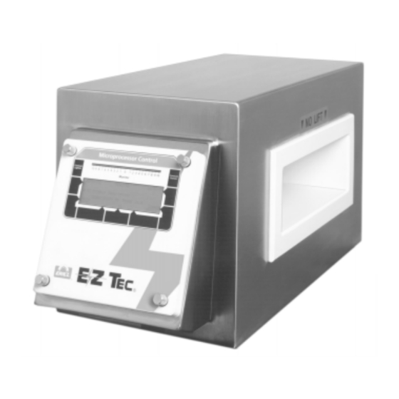
Figures Figure 1. E-Z Tec IV Analog Metal Detector. (E-Z Tec V Analog Unit Is Similar) Figure 2. E-Z Tec IV MPC Metal Detector. (E-Z Tec V MPC Unit Is Similar). ®... - Page 57 Figures (cont.) Figure 3. E-Z Tec Analog Metal Detector Installation Figure 4. E-Z Tec MPC Metal Detector Installation ®...
- Page 58 Figures (cont.) Figure 5. Detect Modes ®...
- Page 59 Figures (cont.) Figure 6. E-Z Tec Major Components Figure 7. E-Z Tec Power Supply (Analog Version Shown) ®...
- Page 60 Figures (cont.) Figure 8. Metal Free Area Figure 9. Typical Conveyor Showing Intermittent Current Loops ®...
- Page 61 Figures (cont.) Figure 10. Methods of Insulating Conveyor Shafts Figure 11. Typical Conveyor - Intermittent Current Loops Removed ®...
- Page 62 Figures (cont.) Figure 12. Metal Detector Mounting Feet Figure 13. Conveyor Belt Splices ®...
- Page 63 Figures (cont.) Figure 14. Electrical Connections ®...
- Page 64 Figures (cont.) Figure 15. Analog Version Control Panel ®...
- Page 65 Figures (cont.) Figure 16. Analog Version Output Control Panel Figure 17. Switch Locations on Analog Output Control Panel ®...
- Page 66 Figures (cont.) CONTRAST CONTROL KEYS MONITOR (LED) BAR LIGHTS DEFLECT TO LEFT AND RIGHT DURING DETECT/REJECT DATE HH:MM:SS MAIN MENU MM/DD/YY KEY FUNCTIONS GO TO EXIT CHANGE TO MATCH PRODUCT SETUP OPTIONS TOUCH PAD REJECT REPORTS PRING THE MENU CURRENTLY FAULT DIAGNOSTICS DISPLAYED...
- Page 67 Figures (cont.) Figure 19. Flowchart of MPC Menu Structure ®...
- Page 68 Figures (cont.) HH:MM:SS ERIEZ MAGNETICS MM/DD/YY HEADQUARTERS EXIT 2200 ASBURY ROAD ERIE, PA 16506-1440 USA SOFTWARE VERSION XXXXXX <PLEASE WAIT> Figure 20 MPC Power Up Display HH:MM:SS MONITOR MM/DD/YY RESET REJECTS # 01 PRODUCT DESCRIPTION SENSITIVITY -- PHASE --.-- MAIN...
- Page 69 Figures (cont.) HH:MM:SS ERIEZ MAGNETICS MM/DD/YY HEADQUARTERS EXIT 2200 ASBURY ROAD ERIE, PA 16506-1440 USA PHONE (814) 835-6000 FAX (814) 838-4960 SOFTWARE VERSION XXXXXX Figure 23 MPC Identification Display HH:MM:SS PRODUCT SETUP MM/DD/YY GO TO # 01 PRODUCT DESCRIPTION EXIT...
- Page 70 Figures (cont.) HH:MM:SS ERIEZ MAGNETICS MM/DD/YY GO TO # 01 PRODUCT DESCRIPTION EXIT TIMED REJECT DIRECT REJECT ..DETECT ON POWER UP? --- SELECT SELECT DOWN INCR HELP DECR Figure 26 MPC Reject Setup Menu HH:MM:SS TIMED REJECT MM/DD/YY # 01 PRODUCT DESCRIPTION EXIT TRAVEL TIME --.--...
- Page 71 Figures (cont.) HH:MM:SS DIRECT REJECT MM/DD/YY # 01 PRODUCT DESCRIPTION EXIT REJECT TIME --.-- AUTO RESET? --- SELECT SELECT DOWN INCR HELP DECR Figure 29 MPC Direct Reject Menu HH:MM:SS PRODUCT DESCRIPTION MM/DD/YY BOTTOM EXIT THIS IS A PRODUCT DESCRIPTION... 0123456789ABCDEFGHIJKLMNOPQRSTUVWXYZ_#., ENTER CANCEL...
- Page 72 Figures (cont.) HH:MM:SS REJECT REPORTS MM/DD/YY REPORT # --- OF --- EXIT RPT# PROD TIME DATE PEAK (mV) ----: --:-- --/-- ---- ----: --:-- --/-- ---- ----: --:-- --/-- ---- SELECT SELECT DOWN INCR HELP DECR Figure 32 MPC Reject Report Screen HH:MM:SS ERASE ALL REPORTS MM/DD/YY...
- Page 73 Figures (cont.) HH:MM:SS FAULT MM/DD/YY EXIT NO FAULT CONDITION CURRENTLY EXISTS. Figure 34A MPC Fault Messages HH:MM:SS FAULT MM/DD/YY EXIT BALANCE FAULT REJECT FAULT SELF-CHECK FAULT CALIBRATION FAULT REFER TO IOM FOR DETAILS Figure 34B MPC Fault Messages HH:MM:SS SETUP PRINTER MM/DD/YY EXIT DATA BITS - BAUD RATE -----...
- Page 74 Figures (cont.) HH:MM:SS SETUP COMMUNICATION MM/DD/YY EXIT DATA BITS - BAUD RATE ----- PARITY ---- SERIAL ADDRESS -- SELECT SELECT DOWN INCR HELP DECR Figure 37 MPC Setup Communication Screen HH:MM:SS SET TIME & DATE MM/DD/YY CANCEL START CLOCK MINUTES -- DAY -- HOURS -- MONTH --...
- Page 75 Figures (cont.) HH:MM:SS PASSWORD MM/DD/YY EXIT CURRENT PASSWORD XXXX <----> 0123456789ABCDEFGHIJKLMNOPQRSTUVWXYZ_#., ENTER LEFT HELP RIGHT Figure 40 MPC New Password Screen HH:MM:SS PRINT OPTIONS MM/DD/YY GO TO EXIT PRINT ALL REPORTS CANCEL PRINT REPORTS REPORT PRINT: ----- SELECT SELECT DOWN INCR HELP DECR...
- Page 76 Figures (cont.) HH:MM:SS SELF CHECK MM/DD/YY GO TO EXIT TEST DISABLED TEST NOW SKIP DETECT/REJECT START TIME (H:M) --.-- DELTA TIME (H:M) --.-- SELECT SELECT DOWN INCR HELP DECR Figure 43 MPC Self Check (Engineer Setup) Screen HH:MM:SS CALIBRATION CHECK MM/DD/YY EXIT TEST DISABLED...
-
Page 77: Appendix A - Printer Operation (Mpc Only)
Eriez Magnetics Connections from the printer cable are made to the E-Z Tec IV or V MPC Metal Detector. The Power Supply PCB, refer to Figure 14. The termi- connector pinout, the printer setup from the MPC, nal block is labeled “PRINTER PORT”... -
Page 78: End Line With
Appendix A (cont.) Printer Operation - MPC Only END LINE WITH REPORTS,” and a problem occurs which interferes You may choose between CR ONLY and CR AND with printer response (for example, the printer is out LF. Choosing CR ONLY (Carriage Return) means of paper), then selecting the command “CANCEL that line feeds must be inserted by the printer. -
Page 79: Setting Up Mpc Printer Serial Port
Appendix A (cont.) Printer Operation - MPC Only SETTING UP MPC PRINTER SERIAL PORT Print the report using the following procedure: The following steps are required to set up the printer a. In the MAIN MENU, use the “SELECT UP” or serial port on the MPC for your particular printer: “SELECT DOWN”... -
Page 80: Printing All Stored Reports
Appendix A (cont.) Printer Operation - MPC Only PRINTING ALL STORED REPORTS CANCELING PRINT ALL REPORTS In the MONITOR menu, press the “MAIN If a problem has occurred with the printer, MENU” key. The MAIN MENU screen will (such as the printer is out of paper or not turned appear. -
Page 81: Appendix B - Variable Speed Tachometer
Appendix B Variable Speed Tachometer Applications involving a variable speed product and An important factor to consider in the design of a requiring automatic contaminant rejection must use tachometer system is the resolution of the separate a tachometer. The tachometer monitors product digital pulses. -
Page 82: Tachometer Wiring Connections
A popular version avail- the pulse width is one-half the period: able from Eriez Magnetics (Part No. 417133) (1 / (42.5 pulses / sec)) x .5 = 0.012 sec provides 10 pulses per revolution with a square wave output;... -
Page 83: Introduction
Do not allow other pieces of equipment to touch INTRODUCTION the detector or stand. If it is necessary to at- Vertical reject E-Z Tec IV’s and V's are mechanically tach an auxiliary support or brace to the stand, and electrically essentially identical to standard... -
Page 84: Electrical
(min) wire. See above for the definition of a trips. Keep such equipment out of the building ground. The ground connection point immediate metal detector area. used for the anti-static chute (if any) can also Figure C1. E-Z Tec IV and V Vertical Reject System Schematic Installation ®... - Page 85 Appendix C (cont.) Vertical Reject Units Figure C2. E-Z Tec IV and V Vertical Reject Sensing Head ®...
-
Page 86: Appendix D - Slim Tec Single Surface Units
In such a case, the uct application. immediate reject facilities of the E-Z Tec IV/V, as described in the main section of this manual, are User-supplied supporting structure must be of most important. -
Page 87: Electrical
Appendix D (cont.) Slim Tec Single Surface Units All idlers on any product conveyor, or directly ELECTRICAL supporting the product (as in a textile applica- The metal detector support must be connected tion), must be electrically insulated. The insu- to an earth or building ground using 12 AWG lation should be installed on one end of each (min) wire. - Page 88 Appendix D (cont.) Slim Tec Single Surface Units Figure D1. E-Z Tec IV and V SlimTec Single Surface Schematic ®...
- Page 89 Appendix D (cont.) Slim Tec Single Surface Units Figure D2. E-Z Tec IV and V SlimTec Single Surface Metal Free Area ®...
-
Page 90: Appendix E - Slim Tec Aperture Units
INTRODUCTION supplementary to the material in the main body of this manual, which must be read and complied with SlimTec Aperture E-Z Tec IV’s and V’s (Figure E-1) for proper installation, operation and maintenance are mechanically and electrically essentially of your E-Z Tec IV/V system. -
Page 91: Electrical
The SOLA should be dedi- (dents, scratches, etc.) than is the stainless cated to source metal detector power only. steel housing of the standard E-Z Tec IV/V unit. Variable frequency drives and other variable This should be considered when selecting a frequency equipment can be a source of radio location for the unit. - Page 92 Slim Tec Aperture Units CLAMP BLOCKS (SUPPLIED) SENSING HEAD TOP VIEW 1.12 5.75 4.25 MTG CNTRS SENSING HEAD APERTURE DIAMETER 25.4 SENSING HEAD END VIEW (GENERIC DIMENSIONS) POWER SUPPLY CONTROL HOUSING Figure E1. E-Z Tec IV and V SlimTec Aperture Schematic ®...
- Page 93 Appendix E (cont.) Slim Tec Aperture Units Figure E2. E-Z Tec IV and V SlimTec Aperture Metal Free Area ®...
-
Page 94: Appendix F - Vfs Packaging Machine Metal Detectors
VFS Packaging Machine Metal Detectors INTRODUCTION MECHANICAL VFS (Vertical Fill and Seal) E-Z Tec IV and V metal It is important that you support the VFS unit detectors are mechanically and electrically identical on stable structure that is not subject to vibra- to standard units with the following exceptions: tion from other equipment. -
Page 95: Electrical
Appendix F (cont.) VFS Packaging Machine Metal Detectors Power and diverter wiring may be run through ELECTRICAL metallic or sealtite conduits, but only plastic If supplied for your application, the black fittings are to be used to attach the conduit to anti-static chute ground wire must be con- the control housing. - Page 96 Appendix F (cont.) VFS Packaging Machine Metal Detectors Figure F1. VFS Metal Detector Schematic ®...
- Page 97 Appendix F (cont.) VFS Packaging Machine Metal Detectors Figure F1. VFS Metal Detector Metal Free Area ®...
- Page 98 This Page Intentionally Left Blank ®...
- Page 99 This Page Intentionally Left Blank ®...
- Page 100 Eriez, Eriez Magnetics, MPC and E-Z Tec are registered trademarks of Eriez Manufacturing Co., Erie, PA 2005 ERIEZ MAGNETICS ALL RIGHTS RESERVED © World Authority in Advanced Technology for Magnetic, Vibratory and Metal Detection Applications HEADQUARTERS: 2200 ASBURY ROAD, P.O. BOX 10608, ERIE, PA 16514-0608 U.S.A.
Need help?
Do you have a question about the E-Z TEC IV and is the answer not in the manual?
Questions and answers