Table of Contents
Advertisement
Quick Links
8
Connect Audio and Video I/O (Continued)
5500 Series HD/SD MPEG-2/DV Playback MediaDeck Module (MDM-5501)
AES Audio Out
AES Audio Out
LTC
Channel A
Unused
Unused
Channel B
1/2
3/4
1/2
3/4
3/4
IN
Chan. A
Chan. B
A
B
Unused
RS-422
HD or SD SDI Video Out
For service only
Unused
HD or SD SDI Video Out
9
Connect AC Power
1. If you are connecting to an automation system, make sure the power switch on the automation
system is off. Attach an AC cord to the AC connector on the automation system.
2. Omneon MediaDecks do not have any power switches. To take full advantage of the dual redundant
power supplies on the Omneon MediaDeck, ensure that separate, isolated power sources are
available. Connect AC cords to the two AC connectors on the Omneon MediaDeck.
Important: Do not plug the AC cords into AC power sources yet. Connecting to an AC power
source will turn on the Omneon MediaDeck.
Omneon MediaDeck Rear Panel
10
Power Up the System
1. Apply power to the Ethernet hub or switch.
2. Apply power to the SystemManager Platform and Keyboard/Monitor Tray, or client PC.
3. From the SystemManager Platform, log on to Microsoft Windows with the user name:
Administrator, and the password: omneon. Both entries are case sensitive.
Note: If an error message appears indicating that a network connection is missing,
click OK and continue with the power-up sequence.
If you have installed SystemManager on a client PC, log on to your client PC.
4. Apply power to the Omneon MediaDeck by connecting the AC cords to the separate power
sources.
5. Check the status LEDs on the Omneon MediaDeck front panel and verify there are no problems.
Refer to "Reading the Front Panel Status LEDs" below.
6. Apply power to the (optional) automation system.
Reading the Front Panel Status LEDs
Descriptions for each of the front panel status LEDs are shown below:
Dark Blue
No reference signal connected
Light Blue
Locked to external reference
Status LEDs
Off
File system initialization not complete
Reference
File Transfer Ethernet
[Solid] File system (FS) started, read-only
Dark Blue
[Blink] FS present but halted
File System
Control Ethernet
[Solid] FS started, read-write
Light Blue
RAID
I/O Module Status
[Blink] No FS present
Off
RAID system initialization not complete
Light Blue
[Solid] Rebuild[s] in progress
Off
Green
[Blink] A RAID set in the FS is compromised
Green
[Solid] One or more RAID sets unprotected
Dark Blue
[Blink] RAID sets present, no FS running
[Solid] All RAID sets are protected
Light Blue
Note: The File System and RAID status LEDs will blink light blue until a file system
[Blink] FS not viable to start
and RAID set are created.
OUT
3. Make sure that the power switch for the SystemManager Platform or client PC is off, and that the
power switch for the Keyboard/Monitor Tray is off as well. Attach an AC cord to the AC connector on
your SystemManager Platform or client PC, as well as your SystemManager Keyboard/Monitor Tray.
SystemManager Platform Rear Panel
Gb 1
Gb 2
SystemManager Platform Rear Panel
4. Connect an AC cord to the AC connector on the Ethernet switch (or hub). Do not plug the AC cord
into an AC power source yet.
8
7
6
5
4
3
2
1
Gigabit Ethernet Switch
11
Run SystemManager
To run SystemManager and begin using your Omneon MediaDeck, refer to
"Running SystemManager and Creating a File System" in the Omneon MediaDeck™ User's Guide.
Replacing Components
To replace components for your Omneon MediaDeck,
refer to the Omneon MediaDeck™ Component
Off
Ethernet initialization failure
Replacement Guide in your MediaDeck kit.
Dark Blue
[Blink] Ethernet hardware or software failure
The Component Replacement Guide includes the
following sections:
[Solid] Ethernet communications OK, IP address present
Light Blue
[Blink] Ethernet communications problem
•
Replacing the Bezel
•
Replacing a Disk Drive
•
Replacing the Drive Cage
•
Replacing an I/O Module
•
Replacing the Processor Module
•
Replacing the Chassis
I/O Module status OK
I/O Module failure
Front
Panel LEDs
Record in progress
Omneon MediaDeck
This guide includes connection instructions for the following
Omneon MediaDeck Modules:
•
5000 Series SD MPEG-2/DV MediaDeck Module (MDM-5001)
•
5220 Series SD MPEG-2 Dual I/O MediaDeck Module (MDM-5221)
•
5320 Series HD/SD MPEG-2 Dual I/O MediaDeck Module (MDM-5321)
•
5400 Series HD/SD MPEG-2/DV Simulcast MediaDeck Module (MDM-5401)
•
5500 Series HD/SD MPEG-2/DV Playback MediaDeck Module (MDM-5501)
Warning: Safe handling
Caution: Unpack and place your Omneon MediaDeck system on a
of this system requires
flat anti-static surface to perform the following installation procedures
TWO people.
contained in this document.
Locate the following items in your Omneon MediaDeck kits:
Omneon MediaDeck Modules
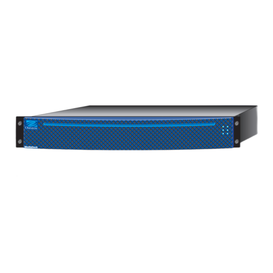
Omneon MediaDeck with
Bezel
Omneon MediaDeck Module(s) factory-installed
Sample System Diagram
A sample system is shown below. Customer-supplied components include the following:
•
Digital VTR (if an Analog VTR is used, external A-D converters are required)
•
Video Monitors
•
RS-422 interconnection cables (DB-9 Male to DB-9 Male)
•
Audio/Video interconnection cables suitable for SDI and AES signal transmission, and monitoring equipment
•
Gigabit Ethernet Hub or Gigabit Ethernet switch
•
Automation System (optional)
Ethernet
Switch or Hub
A/V In
Ethernet
Host
Connections
Omneon MediaDeck
SystemManager Platform
or Client PC
Note: For complete environmental, power, racking, and cable requirements, refer to the Omneon MediaDeck™ User's Guide.
Installation Guide
TM
To access the Omneon MediaDeck documentation:
ftp.omneon.com/updates/omneon/current/MediaDeck/
To access the Omneon SystemManager software and
documentation, go to:
ftp.omneon.com/updates/omneon/current/SystemManager/
Refer to the Omneon MediaDeck™ Read Me First
in your Omneon MediaDeck kit for the password to
download the documentation and software files for the
Omneon MediaDeck and SystemManger.
Caution: Electrostatic discharge can damage components. Make sure to wear
an antistatic wrist strap and attach it to a metal part of the Omneon MediaDeck
chassis when performing the procedures in this guide.
R a
c k
M o
u n t
K it
Eight 500-GB or 1-TB
SystemManager Platform
Rack Mount Kit
Interconnection Cables
SATA disk drives
or Client PC
Technical Support
Omneon Technical Support can be contacted as follows:
For support in the Americas:
Telephone (Toll Free): +1(888) OVN SPT1 (686 7781)
Telephone (Local): +1(408) 585 5200
Fax: +1 (408) 521 2191
Email: support@omneon.com
For support in Europe, Middle East, and Africa:
Telephone: +44 1252 555 450
Fax: +44 1252 377 171
Email: emeasupport@omneon.com
For support in Russia and CIS
Telephone: +7 495 506 5981
A/V Out
Fax: +7 495 937 8290
Email: RUsupport@omneon.com
For support in Japan:
Telephone: +81 3 5565 6737
Fax: +81 3 5565 6736
Email: japansupport@omneon.com
Digital VTR
For support in China (mainland):
Telephone: +86 10 8391 3313
Fax: +86 10 8391 3688
Email: chinasupport@omneon.com
RS-422
For support in Asia Pacific (other territories):
Distribution
Telephone: +65 6671 1499
Fax: +65 6671 1454
Email: apacsupport@omneon.com
For the support page on the Omneon website:
http://www.omneon.com/support
For the support server:
ftp://ftp.omneon.com/Updates/Omneon/Current/
Automation System (optional)
Part Number 28-0134, Revision J.
Omneon and the Omneon logo are trademarks of Harmonic Inc.
*Other names and brands may be claimed as the property of others.
Copyright © 2011. Harmonic Inc. All rights reserved.
Documentation Suite
Advertisement
Table of Contents

Related Manuals for Omneon MediaDeck

Summary of Contents for Omneon MediaDeck
-
Page 1: Installation Guide
A sample system is shown below. Customer-supplied components include the following: Omneon Technical Support can be contacted as follows: 5. Check the status LEDs on the Omneon MediaDeck front panel and verify there are no problems. For support in the Americas: •... - Page 2 Connect to a File Transfer System (Recommended) All automation systems differ in their array of control connectors and method of interfacing with the Omneon MediaDeck system. The following diagrams provide examples for each MediaDeck Module. Refer to the documentation supplied with your automation system for interconnection details.
Need help?
Do you have a question about the MediaDeck and is the answer not in the manual?
Questions and answers