Table of Contents
Advertisement
Quick Links
Advertisement
Table of Contents

Related Manuals for smart-e 4K-8x8-L

Summary of Contents for smart-e 4K-8x8-L
- Page 2 4K-8x8-L USER MANUAL V1.0 SYMBOLS To ensure the safe and correct use of equipment, we use a range of symbols on the equipment and in the manuals. These symbols demonstrate the risk of physical harm or possible damage to property for the user or others and provide guidance on standards and disposal.
- Page 3 4K-8x8-L USER MANUAL V1.0 WARNING In order to ensure the reliable performance of the equipment and the safety of the user, please observe the following matters during the process of installation, use and maintenance. : INSTALLATION Please do not use this product in the following places: places with high levels of dust or soot; places with high electric conductivity;...
-
Page 4: Table Of Contents
4K-8x8-L USER MANUAL V1.0 CONTENTS FUNCTION ................................5 FEATURES................................6 CHASSIS PANEL DESCRIPTION ..........................7 APPLICATION DIAGRAM ............................9 REMOTE CONTROL INTERFACES ...........................10 RS232 SERIAL CONTROL PORT INTERFACE ......................10 TCP/IP CONTROL PORT INTERFACE .......................... 10 5.2.1 TCP/IP CONNECTION VIA SWITCH ........................ -
Page 5: Function
The 4K-8x8-L is a fully loaded 2U rack mountable 8x8 matrix switch incorporating HDBaseT technology. The 4K-8x8-L allows for the input of up to 8 HDMI 1.4, HDCP 2.2 inputs and can be switched to any combination of the 8 available outputs, each of which has a up to 70m CATx HDBaseT output or a local HDMI output. -
Page 6: Features
4K-8x8-L USER MANUAL V1.0 2 FEATURES ▪ 19-inch Rack Mountable Form Factor. ▪ 8x independent HDMI inputs, HDMI 1.4 HDCP 2.2 ▪ 8x independent RJ45 HDBaseT outputs ▪ 8x mirrored HDMI outputs, HDMI 1.4 HDCP 2.2 ▪ DVI 1.0 compliant ▪... -
Page 7: Chassis Panel Description
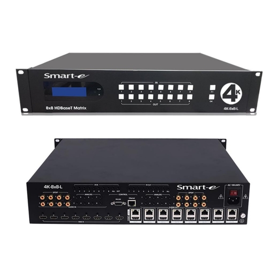
4K-8x8-L USER MANUAL V1.0 3 CHASSIS PANEL DESCRIPTION Front Panel | 4K-8x8-L 1. LCD Display 16x2 character system status display 2. IR receiver Infra-red receiver for supplied IR handset 3. System status LEDs RUN LED Lit green when system processor running IR LED... - Page 8 4K-8x8-L USER MANUAL V1.0 Rear Panel | MDX-8x8 1. 8 x HDMI inputs 2. 8 x RJ45 and HDMI outputs HDMI output mirrored to HDBaseT output 3. 8 x coaxial SPDIF digital audio inputs 4. 8 x 3.5mm stereo jack analogue stereo audio inputs 5.
-
Page 9: Application Diagram
4K-8x8-L USER MANUAL V1.0 4 APPLICATION DIAGRAM © 2018 Smart-e (UK) Ltd www.smart-e.co.uk PAGE | 9... -
Page 10: Remote Control Interfaces
4K-8x8-L USER MANUAL V1.0 5 REMOTE CONTROL INTERFACES 5.1 RS232 SERIAL CONTROL PORT INTERFACE Function FUNCTION Not Used Not Used RS232 send data Not Used RS232 receive data Not Used Not Used Not Used Ground Earth Not Used 5.2 TCP/IP CONTROL PORT INTERFACE 5.2.1 TCP/IP CONNECTION VIA SWITCH... -
Page 11: What Is Included
4K-8x8-L USER MANUAL V1.0 6 WHAT IS INCLUDED ➢ 1x 4K-8x8-L Main Chassis ➢ 1x 4K-8x8-L Infra-red Handset ➢ 1x IEC main lead (Variant dependant on region unit is shipped to) ➢ 10x IR receivers (IR-RX) ➢ 9x IR transmitters (IR TX) ➢... -
Page 12: Accessories
7.1 INFRA-RED RECEIVERS (IR RX) 10 IR RX devices are provided with the 4K-8x8-L, they consist of a stereo jack plug at one end and an infra-red receiver on the other. The stereo jack plugs can be inserted in to any of the IR IN ports on the rear of the 4K- 8x8-L ©... -
Page 13: Infra-Red Transmitters (Ir Tx)
7.2 INFRA-RED TRANSMITTERS (IR TX) 9 IR TX devices are provided with the 4K-8x8-L, they consist of a mono jack plug at one end and an infra-red emitter on the other. The mono jack plugs can be inserted in to any of the IR OUT ports on the rear of the 4K- 8x8-L ©... -
Page 14: Infra-Red Handset
7.3 INFRA-RED HANDSET 1 infra-red handset is supplied with the 4K-8x8-L, it enables the user to direct commands at the front of the unit. For a full description of the commands available and detailed guide on how to use the infra-red handset please refer to the infra-red control section of this manual ©... -
Page 15: Rack Mounting Ears
7.4 RACK MOUNTING EARS The two supplied rack mounting ears can be attached to the front corners of the 4K-8x8-L chassis using the supplied fixing screws. This enables the unit to be mounted in to any standard 19” rack assembly. -
Page 16: Basic Setup
4. Attach any local audio inputs or outputs to their relevant devices 5. Power on all screens, video inputs and audio devices 6. If possible attach a ground connection from the earthing screw on the rear of the 4K-8x8-L to a suitable earth point 7. -
Page 17: Startup Sequence
5. On the rear of the 4K-8x8-L, the LEDs on the RJ45 sockets for the HDBaseT outputs have 2 LEDs to show their status. The green LEDs in the top left of all RJ45 sockets should be blinking green every second to show the HDBaseT chips within the 4K-8x8-L are operating correctly. -
Page 18: Front Panel Operation
This section of the manual describes how to perform the various functions it is possible to achieve via the front panel buttons of the 4K-8x8-L. If the LCD is not illuminated it means it is in standby mode, press and release any button to illuminate the LCD and wake the system. - Page 19 ‘>’ symbol and the input to the left. The input and outputs selected will illuminate their respective buttons on the front of the 4K-8x8-L. Pressing additional output buttons at this stage will illuminate their buttons and add them to the LCD as shown below.
- Page 20 4K-8x8-L USER MANUAL V1.0 Once the desired crosspoints are displayed on the LCD, press the OK button on the front of the 4K-8x8-L. The LCD will update to show the outputs in order along the bottom row of the LCD, what input they are set to.
-
Page 21: Edid Selection
10.2 EDID SELECTION Press and hold the F1 button on the front of the 4K-8x8-L, 4 different EDID modes can be accessed via the front panel using input buttons 2, 3, 4 and 5. The next four sections detail how to use each of these modes. - Page 22 Press the input buttons relevant to the input locations this EDID value is to be assigned. Buttons will illuminate, and LCD will update to as below. Press OK button on the front of the 4K-8x8-L to confirm. © 2018 Smart-e (UK) Ltd www.smart-e.co.uk...
- Page 23 4K-8x8-L USER MANUAL V1.0 The LCD will update to show the read has been successful. The bottom row of the LCD will show a letter followed by a number for its entire length, each letter and number combination relates to the EDID values of the inputs in order.
-
Page 24: Read Edid From Hdbaset Outputs
This function enables the 4K-8x8-L to read EDID values from screens attached to the HDBaseT outputs of the unit to the HDMI inputs. Press and hold the F1 button on the front of the 4K-8x8-L, then press input button 3. - Page 25 Press the input buttons relevant to the input locations this EDID value is to be assigned. Buttons will illuminate, and LCD will update to as below. Press OK button on the front of the 4K-8x8-L to confirm. © 2018 Smart-e (UK) Ltd www.smart-e.co.uk...
- Page 26 4K-8x8-L USER MANUAL V1.0 The LCD will update to show the read has been successful. The bottom row of the LCD will show a letter followed by a number for its entire length, each letter and number combination relates to the EDID values of the inputs in order.
-
Page 27: Set Edid To Internal Value
10.2.3 SET EDID TO INTERNAL VALUE Two sets of EDID values are help internally within the 4K-8x8-L, referred to as preset A and preset B. Their EDID values are shown in the tables below. The values in the tables below can be seen as akin to having a screen with these EDID details attached on that output when either preset is selected for EDID read. - Page 28 4K-8x8-L USER MANUAL V1.0 Press OK button on the front of the 4K-8x8-L to confirm. The LCD will update ready to accept commands in the relevant mode as shown below. © 2018 Smart-e (UK) Ltd www.smart-e.co.uk PAGE | 28...
- Page 29 Press the input buttons relevant to the input locations this EDID value is to be assigned. Buttons will illuminate, and LCD will update to as below. Press OK button on the front of the 4K-8x8-L to confirm. © 2018 Smart-e (UK) Ltd www.smart-e.co.uk...
- Page 30 4K-8x8-L USER MANUAL V1.0 The LCD will update to show the read has been successful. The bottom row of the LCD will show a letter followed by a number for its entire length, each letter and number combination relates to the EDID values of the inputs in order.
-
Page 31: Baud Rate Adjustment
38400 57600 Press and hold the F1 button on the front of the 4K-8x8-L for one second and then press input button 6 to enter baud rate selection mode. Press OK button on the front of the 4K-8x8-L to confirm. - Page 32 ‘>’ symbol. The output buttons on the front of the 4K-8x8-L will now relate to the memory locations as referenced in the table at the beginning of this section. Press the output button for the desired baud rate, for example to set to 9600, press output button 4.
- Page 33 4K-8x8-L USER MANUAL V1.0 Once change has been made the LCD will update to show the change in the current baud rate as shown below. It is strongly advised that the baud rate is not edited unless absolutely necessary, this could cause compatibility issues with Smart-e control applications.
-
Page 34: Shutdown Timer
12 hours 24 hours Press and hold the F1 button on the front of the 4K-8x8-L for one second and then press input button 7 to enter shut down timer mode. Press OK button on the front of the 4K-8x8-L to confirm. - Page 35 ‘>’ symbol. The output buttons on the front of the 4K-8x8-L now relate to the memory locations as shown in the table as the start of this section. For example to set the shut down timer to 24 hours, press output button 8.
- Page 36 4K-8x8-L USER MANUAL V1.0 Once OK button pressed, the LCD will update to show the newly selected shut down time. © 2018 Smart-e (UK) Ltd www.smart-e.co.uk PAGE | 36...
-
Page 37: System Settings
Reboot Factory Reset Press and hold the F1 button on the front of the 4K-8x8-L for one second and then press input button 8 to enter system settings mode. Press OK button on the front of the 4K-8x8-L to confirm. - Page 38 At this point user can press either output button 1 to reboot the unit or output button 2 to restore the unit to factory default settings. Press OK button on the front of the 4K-8x8-L to confirm. Whichever option is selected the unit will briefly shut down and go through the startup sequence. If reboot has been selected, all settings of the unit will be remembered.
-
Page 39: Infra-Red Control
4K-8x8-L USER MANUAL V1.0 11 INFRA-RED CONTROL The 4K-8x8-L is supplied with an infra-red handset which can be used to direct infra-red control commands at the infra-red receiver on the front of the 4K-8x8-L. © 2018 Smart-e (UK) Ltd www.smart-e.co.uk... - Page 40 The handset can also be used in conjunction with an IR RX unit attached using its 3.5mm jack plug to the EXT IR IN socket on the rear of the 4K-8x8-L. Either of these methods are applicable for the instructions within this section of the manual.
-
Page 41: Crosspoint Control
4K-8x8-L USER MANUAL V1.0 11.1 CROSSPOINT CONTROL By default, the 4K-8x8-L is in the correct mode to accept video crosspoint commands. Pressing any of the input or output buttons will initiate a crosspoint command. © 2018 Smart-e (UK) Ltd www.smart-e.co.uk... -
Page 42: Setting A Single Crosspoint
4K-8x8-L USER MANUAL V1.0 11.1.1 SETTING A SINGLE CROSSPOINT To set a single crosspoint a user can press any number from 1-8 within the output section of the handset, this relates to both the local HDMI output and remote HDBaseT output as well as any de-embedded audio outputs which may be enabled. - Page 43 4K-8x8-L USER MANUAL V1.0 © 2018 Smart-e (UK) Ltd www.smart-e.co.uk PAGE | 43...
-
Page 44: Setting Multiple Crosspoints
4K-8x8-L USER MANUAL V1.0 11.1.2 SETTING MULTIPLE CROSSPOINTS To set multiple crosspoints simultaneously, first press one at a time all of the outputs the user wishes to change using the 1-8 output number buttons. Next press the input button the user wishes to switch all previously selected outputs to using the 1-8 input buttons. - Page 45 4K-8x8-L USER MANUAL V1.0 © 2018 Smart-e (UK) Ltd www.smart-e.co.uk PAGE | 45...
- Page 46 4K-8x8-L USER MANUAL V1.0 © 2018 Smart-e (UK) Ltd www.smart-e.co.uk PAGE | 46...
-
Page 47: Set All Crosspoints Simultaneously
4K-8x8-L USER MANUAL V1.0 11.1.3 SET ALL CROSSPOINTS SIMULTANEOUSLY If the user wishes to set all outputs to a single input, they can first press the ALL button within the output section of the handset. Then the user presses the desired input all outputs are to be switched to using the 1- 8 number keys within the input section of the handset. - Page 48 4K-8x8-L USER MANUAL V1.0 © 2018 Smart-e (UK) Ltd www.smart-e.co.uk PAGE | 48...
-
Page 49: Set Unit To Point-To-Point Mode
4K-8x8-L USER MANUAL V1.0 11.1.4 SET UNIT TO POINT-TO-POINT MODE A button is provided in the output section of the handset labelled PTP, this stands for point to point. Pressing this button will map each output to its respective input, output 1 to input 1, output 2 to input 2, output 3 to input 3 etc…... -
Page 50: Ir System Controls
This can be done with the use of the TAB, OK and input/output buttons. Firstly, press the TAB button on the IR handset, this will illuminate input button 1 on the front of the 4K-8x8-L. The input and output buttons, 1 to 8 in both sections can now be used as well as the OK button to perform the same functions and in the same manner as outlined in section 10. -
Page 51: Rs232 Control
4K-8x8-L USER MANUAL V1.0 12 RS232 CONTROL It is possible to control the 4K-8x8-L via RS232. This can be achieved by connecting the 4K-8x8-L via the D9 connector on the rear of the unit to a PC, laptop or third-party control system. -
Page 52: Tcp/Ip Control
13.1 COMMAND LINE COMMANDS OVER ETHERNET Using a CATx cable, attach the 4K-8x8-L to either your network or to a local PC with reference to the diagrams above. Alternatively, you could also use an ethernet output of a third-party controller if that option is available. -
Page 53: Using The Integrated Web Server
Once connected to the network the unit can be switched on. Next open a web browser of a device on the same network and navigate to the IP address of the 4K-8x8-L, which by default is 192.168.1.88 You will be met by the following screen. -
Page 54: Setting Video Crosspoints
4K-8x8-L USER MANUAL V1.0 13.2.1 SETTING VIDEO CROSSPOINTS When the web page is initially opened, by default it will begin on the video crosspoint tab. If not already on the video crosspoint table, left click on the video tab in the top left of the screen. - Page 55 4K-8x8-L. To submit these commands to the 4K-8x8-L, left click on the OK button above the crosspoint grid. Nothing will update on the screen at this point but the video outputs should be seen to change.
-
Page 56: Edid Management
4K-8x8-L USER MANUAL V1.0 13.2.2 EDID MANAGEMENT To select the EDID management mode of the 4K-8x8-L web browser, left click on the EDID tab in the top left of the window. This will open the EDID management grid with the current settings highlighted in either green or black. - Page 57 4K-8x8-L to read EDID from this respective HDMI output. When in any of the output columns a box is marked black this is telling the 4K-8x8-L to read EDID from the respective HDBaseT output.
-
Page 58: Ip And Gateway Settings
4K-8x8-L USER MANUAL V1.0 13.2.3 IP AND GATEWAY SETTINGS To select the IP and gateway settings of the 4K-8x8-L web browser, first left click on the IP tab in the top left of the window. This will present the user with the main IP settings interface. -
Page 59: Hdbaset Cabling
Smart-e support immediately. HDBaseT signals can be susceptible to noise, causing image loss or snowy effects on output screens. The best way to mitigate against these problems is by using a high quality CATx cable. Smart-e specify cable as below. -
Page 60: Technical Specification
4K-8x8-L USER MANUAL V1.0 15 TECHNICAL SPECIFICATION Audio and Video Ports Input Ports 8x HDMI – 8x coaxial SPDIF – 8x 3.5mm stereo audio Output Ports 8x HDMI – 8x coaxial SPDIF – 8x 3.5mm stereo audio – 8x HDBaseT... - Page 61 4K-8x8-L USER MANUAL V1.0 Fall Time <0.3T bit (20-80%) Maximum Transmission Delay 5ns (+/- 1ns) Signal Strength T.M.D.S +/- 0.4V p-p Minimum/Maximum Level T.M.D.S 2.9V/3.3V Impedance 50Ω EDID Optional default EDID and load function Maximum DC Offset error 15mV Maximum Input cable...
Need help?
Do you have a question about the 4K-8x8-L and is the answer not in the manual?
Questions and answers