Advertisement
Quick Links
BIS M-628-075-A01-03-ST34
High Frequency Passive Radio Frequency,
Identification Processor unit
QUICK REFERENCE GUIDE
This document provides instructions and information
designed to assist users in the hardware setup of the BIS M-
628-075-A01-03-ST34
RFID
Processor
unit.
configuration details see the BIS M62_ Manual.
PACKAGE CONTENTS
Qty
Description
1
BIS M-628-075-A01-03-ST34 Processor unit
1
Cobalt HF Series Configuration Tag
1
This Installation Guide
2
M5 x 20 mm Antenna Mounting Screws
2
M5 Antenna Mounting Washers
1
Hex Wrench for Antenna Mounting
1
BCC06ZF M12 5PF Power Connector
TECHNICAL DATA
ELECTRICAL FEATURES
Power Supply
12 to 30 VDC
DC Input Current
500 to 300 mA
Communication Interface
Profinet IO
Data Rate
up to 100 Mbps
RADIO FEATURES
Frequency
13.56 MHz
Air Protocols
ISO 14443A, ISO 15693
Conducted Output Power
1 W
ENVIRONMENTAL FEATURES
Operating Temperature
-20° to +50 °C
(-4° to +122 °F)
Storage Temperature
-20° to +70 °C
(-4° to +158 °F)
Humidity max.
90% non condensing
Protection Class
IP65*
EN 60529
PHYSICAL FEATURES
Dimensions
164 x 112 x 48 mm
(6.48 x 4.41 x 1.88 in)
Weight
560 g (19.8 oz)
Enclosure
Powder Coated Al
USER INTERFACE
LED Indicators
READY, RF, COM, NET
STATUS, MODE STATUS,
LINK 1, LINK 2
* When all connectors, sealing caps, and antenna are correctly
installed.
The BIS M-62_ Processor unit and its antenna are
intended for indoor use only.
Minimum Mounting Distance Between Adjacent Antennas.
BIS M
-371
-372
-373
-370
-371
60 cm
75 cm
90 cm
50 cm
-372
75 cm
90 cm
1.2 m
65 cm
-373
90 cm
1.2 m
2 m
90 cm
-370
50 cm
65 cm
90 cm
50 cm
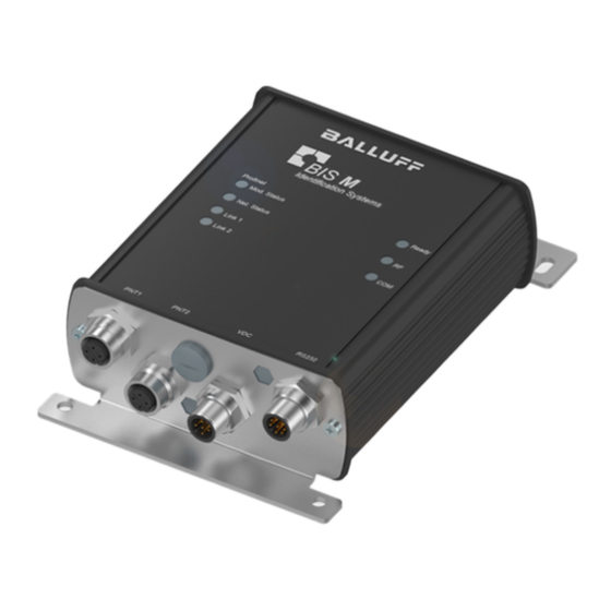
GENERAL VIEW
For
CONNECTIVITY
M12 4-pin D-Coded Female Connector (Profinet Port 1)
PIN 4:
RX-
PIN 3:
TX-
M12 4-pin D-Coded Female Connector (Profinet Port 2)
PIN 4:
RX-
PIN 3:
TX-
M12 5-pin Male Connector (Power Supply)
PIN 4:
PIN 5:
N/C
N/C
PIN 1:
N/C
M12 8-pin Male Connector (RS232)
LED INDICATORS
READY
green
RF
amber
COM
amber
MOD STATUS
green/red
NET STATUS
green
(PNT) LINK1
PIN 1:
(PNT) LINK2
amber
TX+
PIN 2:
RX+
PIN 1:
BCC06ZF
TX+
PNT1
to Power Supply
PIN 2:
RX+
PNT2
to Profinet Master
See the BIS M62_ Manual for a complete list of accessories including alternative cables and
connectors.
DIMENSIONS
PIN 3:
GND
112
[4.41]
PIN 2:
VDC
43.0
[1.69]
54.0
[2.13]
The READY LED is ON after the power up
sequence has completed.
The RF LED illuminates when RF power is being
transmitted by the antenna.
The COM (communications) LED flashes ON and
OFF when data is being transmitted between the
antenna and a tag.
When in Continuous Read mode, the COM LED
will remain ON and will turn OFF briefly only while
data is being read from or written to a tag.
SOLID GREEN: initialized. Normal Operation
FLASHING GREEN (1 FLASH): diagnostic
event(s) present.
SOLID RED: exception error
(see HF Series Processor unit Reference Manual
for other specific LED conditions)
SOLID GREEN: IO Processor unit connected in
RUN
FLASHING GREEN: IO Processor unit connected
in STOP
SOLID AMBER: Profinet link established
Typical Layout
to Configuration
PC
mm
in
INSTALLATION GUIDELINES
•
RF performance and read/write range can be negatively
impacted by the proximity of metallic objects and liquids.
Avoid mounting the BIS M-37_ within 15 cm (6 inches) of
any metallic object or wet surface.
•
Do not route cables near other unshielded cables or
near wiring carrying high voltage or high current. Cross
cables at perpendicular intersections and avoid routing
cables near motors and solenoids.
•
Avoid mounting the processor unit near sources of EMI
(electro-magnetic interference) or near devices that
generate high ESD (electro-static discharge) levels.
Always use adequate ESD prevention measures to
dissipate potentially high voltages.
•
If electrical interference is encountered (as indicated by
a significant reduction in read/write performance),
relocate the processor unit to an area free from potential
sources of interference.
INSTALLATION
The BIS M-628-075-A01-03_ processor unit is designed for
Profinet RFID applications, where the processor unit is
connected as a slave node in a Profinet IO network via
compatible cables directly to a Profinet Master (host). The
default IP Address is 192.168.253.110.
1.
Select a suitable location for the Cobalt HF Processor
unit/Antenna.
2.
Mount the BIS M-37_ Antenna to the BIS M Processor,
either Directly or Remotely, as described in the BIS M-
37_ Installation Guide included with the antenna.
3.
Mount the processor unit and antenna to your mounting
fixture using M5 (or #10) diameter screws (not
included) and secure them with appropriate washers
and nuts. Tighten screws to 1.7 Nm or 15 lbs per inch
± 10%.
4.
Attach Profinet-compatible data cables to the 4-pin D-
Coded, female M12 interface connectors on the Cobalt.
Connect the other end of the cables to your Profinet
network.
5.
Build a power supply cable using the BCC06ZF M12 5-
pin female connector. Use 18 AWG (max) to 24 AWG
(min) wires for connection to the power supply lines
according to the Vdc connector pinout. Connect the
BCC06ZF M12 5-pin female connector to the M12 5-pin
male connector on the processor unit. Connect the
other end of the cable (wires or user-supplied
connectors) to the power supply.
6.
Apply power to the processor unit after all cable
connections have been made. The LEDs on the unit will
flash. The READY LED is ON after the power up
sequence has completed.
To configure and control the BIS M-628-075-A01-03-ST34
processor unit and send RFID commands for testing
purposes, download and install the Balluff Dashboard™
Utility from www.balluff.com. The Dashboard Configuration
Tool uses the PC RS232 serial port to communicate to the
processor
unit's
RS232
serial
port.
To
enable
communication:
(over)
Advertisement

Subscribe to Our Youtube Channel
Related Manuals for Balluff BIS M-628-075-A01-03-ST34


Summary of Contents for Balluff BIS M-628-075-A01-03-ST34
- Page 1 * When all connectors, sealing caps, and antenna are correctly sequence has completed. installed. M12 8-pin Male Connector (RS232) To configure and control the BIS M-628-075-A01-03-ST34 The BIS M-62_ Processor unit and its antenna are processor unit and send RFID commands for testing intended for indoor use only.
- Page 2 9600 baud, 8 data bits, 1 stop bit, no parity and no handshaking. Run the Balluff Dashboard™ Utility. COMPLIANCE Only Balluff BIS M37_ antennas are certified for use with the BIS M-628-075-A01-03-ST34 processor units. This product is intended to be installed by Qualified Personnel only.
Need help?
Do you have a question about the BIS M-628-075-A01-03-ST34 and is the answer not in the manual?
Questions and answers