Advertisement
Table of Contents
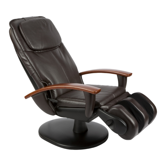
HT-100/102/103/120/130/140
410/430/450/3100/3200/3300
It is imperative that Human Touch
products are repaired in a manner that ensures product safety and regulatory compliance and that is fully consistent with the practices used
®
during the manufacturing process. Therefore, Human Touch requires that all product repairs are performed using only factory-new parts and in accordance with these repair
instructions. Failure to adhere to these instructions voids the product warranty and releases Human Touch from all liability for injury or product damage resulting from the repair.
Tools Required: Pliers, vice grip, Phillips-head screwdriver, small hammer, nail clipper or other instrument suitable for cutting zip ties, new zip ties
NOTE: SAVE ALL REMOVED PARTS FOR USE DURING REASSEMBLY
GET READY
1. Remove the head pillow and backrest pad, following the instructions in the Use & Care manual.
2. Push down on the backrest release lever, then fold the backrest forward onto the chair seat (Fig.1).
3. Power off the chair and unplug it.
REMOVING THE BACKREST
1. Locate the connector box on the bottom right-hand side of the chair (Fig.2).
2. Using a Phillips-head screwdriver, remove the two screws that secure the connector box cover, remove the cover, then disconnect the connectors.
3. Using a nail clippers, or other suitable instrument, cut and remove all zip ties that secure the backrest connectors and cable harness to the bottom of the
chair, being careful not to cut the harness casing.
Connector box
(Right-hand side of the chair)
(Fig.2)
REPLACING THE BACKREST
Backrest release lever
Sept 19, 2011
SERVICE LEVEL: 3
(Fig.1)
1
Advertisement
Table of Contents

Related Manuals for Human Touch HT-103


Summary of Contents for Human Touch HT-103
- Page 1 Therefore, Human Touch requires that all product repairs are performed using only factory-new parts and in accordance with these repair instructions. Failure to adhere to these instructions voids the product warranty and releases Human Touch from all liability for injury or product damage resulting from the repair.
- Page 2 4. Pull gently outward on the bottom of one of the rear side panel covers to remove it (Fig.3). 5. Using a Phillips-head screwdriver, remove the screw and washers that secure the metal hinge pin to the chair (Fig.4). 6. Using a pliers (or a vice grip if necessary), pull the hinge pin toward you until it is freed from the chair (Fig.5). NOTE: The hinge pin is lubricated. Place it on a disposable object, such as a paper towel, to avoid damaging the flooring beneath the chair. NOTE: When the hinge pin is removed, the two spacers that are located between the backrest and the chair base will most likely fall off (Fig.6). Be sure to set these spacers aside for use during reassembly. 7. Repeat steps 4 - 6 on the other rear side panel panel. 8. Carefully lift the backrest up and off the chair base. Hinge pin Washer Screw (Fig.4) (Fig.3) Backrest Hinge pin spacers (Fig.6) (Fig.5)
- Page 3 INSTALLING THE NEW BACKREST 1. Place the new backrest into position, face-down on the chair base. 2. From the outside of one of the side panels, insert the hinge pin through the hole, just until it is visible on the inside of the side panel. 3. Place the two spacers into position on the inside of the side panel, with the smaller spacer between the larger spacer and the side panel, then push the hinge pin through both spacers (Fig.7). 4. Use your fingers to line up the bracket in the side of the backrest and the hinge pin; you will need to pull up slightly on the lower part of the backrest to properly align the hinge pin with the bracket. 5. Insert the hinge pin as far into the bracket as possible, then use a small hammer to install it completely into the bracket. 6. Secure the hinge pin to the side panel using a Phillips-head screwdriver and the screw you removed earlier. 7. Replace the side panel cover, by aligning the plugs on the inside of the cover with the corresponding holes on the chair, then pushing the cover firmly into place (Fig.8). Backrest Larger spacer Smaller spacer Hinge pin Side panel (Fig.7) (Fig.8)
- Page 4 8. Repeat steps 2 - 7 on the other side panel. 9. Reconnect the cables at the connector box on the bottom right-hand side of the chair (Fig.9). 10. Using a Phillips-head screwdriver, secure the connector box cover using the two screws you removed earlier. 11. Replace the zip ties you removed previously, to secure the connector boxes and cables to the bottom of the chair. 12. Reinstall the chair pads, following the instructions in the Use and Care Guide. 13. Plug in and power on the chair, then verify that both the massage and recline functions work. Connector box (Right-hand side of the chair) (Fig.9) Please send any questions or comments regarding these instructions to: documentation@humantouch.com © 2011 Human Touch , LLC. ®...
Need help?
Do you have a question about the HT-103 and is the answer not in the manual?
Questions and answers