Table of Contents
Advertisement
Quick Links
GE
Sensing
Introduction
®
The GE Telaire Ventostat
8001/
8002 carbon dioxide (CO
) sensors and
2
controllers are designed for Demand
Controlled Ventilation (DCV) in
buildings. This approach, using CO
an indicator of occupancy, allows
ventilation based on actual occupancy
while still maintaining ASHARE
recommended per-person ventilation
rates. Over ventilation of buildings can
be reduced, energy can be saved, and
quality can be optimized.
The optional black case (PN 8001B and
PN 8002B) is UL94-V5 rated, making
these models suitable for mounting
directly inside the ductwork. Typical
®
applications for Ventostat
8001/8002 series include office buildings,
conference rooms, schools, retail stores, restaurants, gymnasiums, and
movie theatres.
Installing the Sensor
Use of cellular telephones or radio transceivers within two (2) feet of the
sensor during calibration process could cause sensor interference,
calibration errors and affect sensor accuracy. Please refrain from using
these devices during sensor calibration.
Install the mounting plate and sensor as follows:
1. Prepare for installation by using the mounting holes configured for
US or European junction boxes.
2. Use the mounting plate as a template to mark the mounting holes.
See Figure 1, View A below.
Mounting
Plate
Bottom Clips
View A
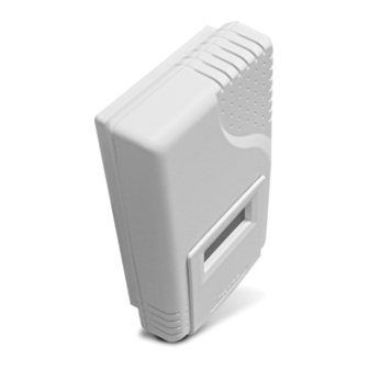
Figure 1: Ventostat
as
2
NOTICE!
Ventostat
CO
Sensor/
2
Controller
Top Clips
clear
mode
View B
View C
®
CO
Controller - Mounting
2
Telaire Ventostat
3. Secure the mounting plate to the wall or junction box and make
necessary wire connections.
4. Mount the controller on the base by aligning the top clips and then
securing to the bottom clips, as shown in Figure 1, View B above. A
"snap" sound will indicate that the sensor is secure. The sensor will
now have power. A 2 minute warm-up will take place. After 2
minutes, the sensor will stabilize and display the "Normal Mode"
(current CO
2
5. At this point one of nine preset programs or one custom channel can
be selected for operation. See the section "Configuring the Sensor"
on page 3.
6. Finish installation by sliding the cover over the menu keys and
secure with the supplied screw.
Mounting the Sensor into the Duct
The 8001B and 8002B have the UL94-V5 rated black case and are
specifically designed for mounting inside the return air ductwork. When
mounting these products inside the ductwork, seal the hole around the
wires and leave the duct insulation in place to prevent condensation
which may damage the sensor.
Pitot Tube Installation for the
8001 and 8002
Install the mounting bracket, then install the pitot tube assembly as
follows:
Note:
The length of the Tygon
maintain optimum accuracy, the tubing should not be
lengthened. If the sensor is mounted closer than three
feet, the excess tubing should be shortened to avoid
interference with mechanical or moving devices.
1. To mount the pitot tube, drill one 7/8" hole through the duct as
shown in Figure 2 below.
Drill One Hole
7/8" in Diameter
enter
Drill Two Machine
Screw Holes
Figure 2: Pitot Tube - Installation
®
8000 Series CO
User Instructions
readings).
®
tubing is three feet. In order to
H
Filter must be
attached to the
"H" side of the
pitot tube
FLOW
View in Direction of A
Mounting
Flange
Sensors
2
L
T62659-007
October 2006
Page 1 of 7
Advertisement
Table of Contents

Related Manuals for GE Telaire Ventostat 8001


Summary of Contents for GE Telaire Ventostat 8001
- Page 1 ® 4. Mount the controller on the base by aligning the top clips and then The GE Telaire Ventostat 8001/ securing to the bottom clips, as shown in Figure 1, View B above. A 8002 carbon dioxide (CO ) sensors and “snap”...
-
Page 2: Typical Wiring Diagrams
The typical wiring diagrams appear in Figure 4 through Figure 8 2. Insert the pitot tube and mark the two remaining holes for the mounting screws. below. 3. Punch or drill the two marked holes. Isolated AC Power 4-Wire System AC Power 3-Wire System 4. -
Page 3: Configuring The Sensor
500 ft increments. Diagrams ABC Logic™ Self Calibration System Configuring the Sensor All GE Telaire 8000 series sensors are factory set with the ABC Logic The sensor has two different settings: (Automatic Background Calibration) self calibration feature ON. This •... -
Page 4: Custom Settings
the extensive use of catalytic converters that tend to remove Setting 9 is intended for use in parking garages where CO can be used as an indicator of the presence of combustion fumes. As part of most most of the carbon monoxide from vehicle exhaust. The 700 types of combustion, CO is generated at a rate that is 50 times or more ppm setting should maintain levels of other exhaust... - Page 5 For Non-Standard (Custom) Settings Design Ventilation Rate The non-standard (custom) settings can be changed at any time after the sensor is powered up. The seven settings (variables) are: Ventilation Based On CO DCV • PPM Range • Scale (proportional or exponential) •...
-
Page 6: Troubleshooting
UIP 8000 computer interface or checking the output signal on the building automation system. 4. If there is no output signal, call GE Telaire or your distributor/dealer for a return authorization number Page 6... -
Page 7: Specifications
2072 Accuracy Warranty Repairs ±100 ppm or 7%, whichever is greater GE Sensing will repair Telaire product that fails to meet the terms Elevation (Pressure) Correction provided for in the Return and Warranty Policy Statement (See, http:// www.gesensing.com/service/brochures.htm).Warranty period shall start Add 0.13% of reading per mm Hg decrease from 760 mm Hg (On-board...
Need help?
Do you have a question about the Telaire Ventostat 8001 and is the answer not in the manual?
Questions and answers