Table of Contents
Advertisement
Quick Links
M-24C ORION
Magni Gyro Srl
Sede Legale ed Operativa - Via Volpina, 23
21010 Besnate (VA) – Italy
TITLE: M24C FLIGHT MANUAL
CODE: 24C_AUS
PRODUCT: M-24 C
e-mail: info@magnigyro.it sito web: www.magnigyro.it
N° Registro Imprese di Varese 02207000023 - P.IVA e c.f.:02207000023
M24C FLIGHT MANUAL
ISSUE B _ DECEMBER 2011
Tel. +39 0331 274816 – Fax +39 0331 274817
Capitale sociale € 80.000 interamente versato
M24C_AUS
.
Advertisement
Table of Contents

Related Manuals for Magni Gyro M-24C Orion


Summary of Contents for Magni Gyro M-24C Orion
- Page 1 ISSUE B _ DECEMBER 2011 TITLE: M24C FLIGHT MANUAL CODE: 24C_AUS PRODUCT: M-24 C M-24C ORION Magni Gyro Srl Tel. +39 0331 274816 – Fax +39 0331 274817 Sede Legale ed Operativa - Via Volpina, 23 e-mail: info@magnigyro.it sito web: www.magnigyro.it 21010 Besnate (VA) –...
- Page 2 Engine Serial Number: Aircraft Designed and constructed by: Magni Gyro Srl Pilot’s handbook prepared and issued by: Magni Gyro Srl This gyroplane shall at all times be operated in accordance with this manual. No part of this manual may be reproduced or transmitted in any form or by any means, electronic or mechanical, including photocopying, recording or by any information storage or retrieval system, without prior permission from Magni Gyro.
- Page 3 M24C_AUS M24C FLIGHT MANUAL GENERAL This Pilot Operating Handbook applies only to the aircraft detailed on page 0-4. It is the responsibility of the pilot to be familiar with the content of this handbook, including any amendments. Units of measure The following units are used in this Handbook and where appropriate on the instruments and placards.
- Page 4 M24C_AUS M24C FLIGHT MANUAL RECORD OF AMENDMENTS This page 4 and subsequent amendment pages 4/1 etc, will be reissued as necessary with each amendment list. It is the responsibility of the owner to insure that the amendments are incorporated in the Pilot’s Handbook.
-
Page 5: Table Of Contents
M24C_AUS M24C FLIGHT MANUAL INDEX SECTION 1 INTRODUCTION - OBJECT - PERMITTED OPERATIONS - LAY-OUT - CHECKLISTS - DEFINITIONS 1.5.1 - Definitions used in the manual 1.5.2 - Definitions used to identify the parts of the gyroplane - DICTIONARY OF COMMONLY USED ABBREVIATIONS SECTION 2 GENERAL DESCRIPTION AND INSTRUCTIONS FOR USE - THE GYROPLANE... - Page 6 M24C_AUS M24C FLIGHT MANUAL SECTION 3 OPERATING LIMITS - INTRODUCTION - MINIMUM CREW - POWER LIMITATIONS - ENGINE OVER-SPEED - SPEED LIMITS - FLIGHT MANOEUVRE LIMITATIONS - LOAD FACTOR LIMITATIONS - FLIGHT ENVELOPE - CENTRE OF GRAVITY LIMITATIONS 3.10 - LOAD LIMITATIONS 3.11 - BAGGAGE COMPARTMENT 3.12...
- Page 7 M24C_AUS M24C FLIGHT MANUAL 4.12.4 - Level turns 4.12.5 - Level turns 4.12.6 - Turning whilst climbing 4.12.7 - Speed change 4.13 - UNUSUAL MANOEUVRES 4.13.1 - Slow flight and flight behind the power curve 4.13.2 - Vertical descent 4.13.3 - Large power changes 4.14 - LANDING MANOEUVRES 4.14.1 - Before landing...
- Page 8 M24C_AUS M24C FLIGHT MANUAL SECTION 7 APPENDIX - APPENDIX 1 - REFUELLING DATA 7.1.1 - Fuels 7.1.2 - Brake oils 7.1.3 - Lubricants - APPENDIX 2 - ORDINARY MAINTENANCE SCHEDULE - APPENDIX 3 - ENGINE PARAMETERS 7.3.1 - ENGINE PERFORMANCE 7.3.2 - ENGINE TORQUE 7.3.3...
- Page 9 M24C_AUS M24C FLIGHT MANUAL SECTION INTRODUCTION ISSUE B PAGE December 2011...
-
Page 10: Object
M24C FLIGHT MANUAL 1.1 OBJECT This manual is intended to give all the necessary information, which the operator flying the M-24C Orion gyroplane must comply with in order to ensure the safety and effective operation. The instructions provide the pilot with a general knowledge of the gyroplane and of its features, as well as with a specific knowledge of the normal and emergency operation procedures. -
Page 11: Definitions
M24C_AUS M24C FLIGHT MANUAL 1.5 DEFINITIONS 1.5.1 DEFINITIONS USED IN THE MANUAL To ensure safe functioning of the gyroplane, specific symbols are used in this manual to highlight the relative importance of particular items. The symbols used in this manual are as below: WARNING DANGER: Operation, technical and other procedures which, if not followed carefully, may expose the operator to the risk of serious accident or death. -
Page 12: Dictionary Of Commonly Used Abbreviations
M24C_AUS M24C FLIGHT MANUAL 1.6 DICTIONARY OF COMMONLY USED ABBREVIATIONS Cylinder Head Temperature Exhaust Gas Temperature Feet Gravitational acceleration Gravitational constant Glide Angle Global Positioning System inHg Inches of Mercury Kn (Knot) Nautical mile per hour Indicated Air Speed Manifold Pressure Millibar (statute) Miles per Hour Maximum Take-off Weight... -
Page 13: General Description And Instructions For Use
M24C_AUS M24C FLIGHT MANUAL SECTION GENERAL DESCRIPTION AND INSTRUCTIONS FOR USE ISSUE B PAGE December 2011... -
Page 14: The Gyroplane
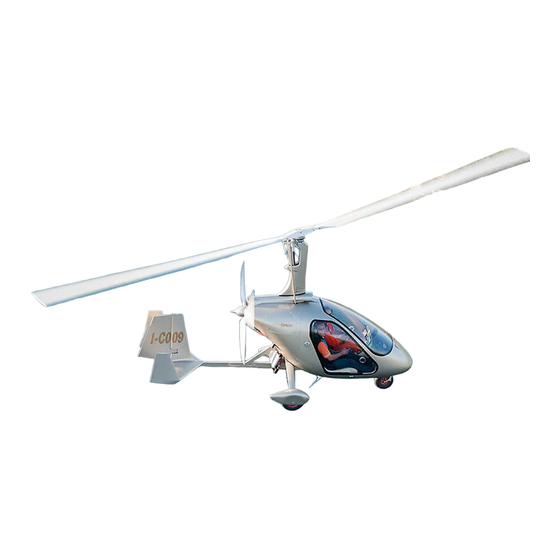
M24C_AUS M24C FLIGHT MANUAL 2.1 THE GYROPLANE The M-24C Orion is a single-engine two-seat gyroplane with a primary structure made of steel and a carbon fibre fuselage. The gyroplane is equipped with a fixed front tricycle landing gear. The side-by-side configuration allows for the carriage of two crew members in the cockpit. The power unit is a piston engine in a pusher configuration driving a three-bladed propeller with ground adjustable pitch. -
Page 15: Flight Characteristics In Level Conditions
M24C_AUS M24C FLIGHT MANUAL 2.1.3 FLIGHT CHARACTERISTICS IN LEVEL CONDITIONS 2.1.3.a LOW SPEED The flight characteristics and manoeuvrability at low speed are excellent. In any flight conditions, the roll and pitch controls are effective down to zero airspeed. In any flight conditions, yaw control is effective down to an IAS of 20 mph (17.5 Kn). Yaw control can be maintained down to zero airspeed by maintaining engine rpm at more than 3,000 r.p.m. -
Page 16: Overall Dimensions
M24C_AUS M24C FLIGHT MANUAL 2.2 OVERALL DIMENSIONS (Fig. 1 and 2) The overall dimensions are indicated below: Rotor diameter..................... 8.574 mm (28.20’) Total length ........................4.400 mm Width .........................1.800 mm Height (without rotor) ....................2760 mm Maximum height (with stick forward) ................2810 mm PAGE ISSUE B December 2011... -
Page 17: Technical Data
M24C_AUS M24C FLIGHT MANUAL 2.3 TECHNICAL DATA Weights Dry weight: 290 kg Empty weight 297 kg MTOW: 500 kg Limited to 450 Kg if required by the requirements in force in the country the gyroplane is registered in or operated in. Performance - Never Exceed Speed 105 mph (90 Kn) - Page 18 M24C_AUS M24C FLIGHT MANUAL Cruise at 75% of power 30.5 inHg Cooling System Cooling system type: air / liquid Coolant radiator 3 Litres Oil radiator 4 Litres Electrical Installation Operating Voltage 12 V Battery 12 V - 13 Ah Tyres Nose wheel 4.004 6PLY Inflating pressure...
-
Page 19: Identification Placard
M24C_AUS M24C FLIGHT MANUAL 2.4 IDENTIFICATION PLACARD (Fig. 1) The manufacturer’s identification placard (1) is located inside the cockpit, on the lower right side of the central console. Description of the placard Model Serial number Engine type Production date ISSUE B PAGE December 2011... -
Page 20: General Configuration
All the main components of the gyroplane are listed in this chapter. Whenever communicating with MAGNI GYRO (via telephone, e-mail, fax, etc.), pilots and operators should always use the terminology used in the section in order to identify the components consistently. - Page 21 M24C_AUS M24C FLIGHT MANUAL Rear - external (Fig. 3) Rotor brake Bendix Control rods Trim control Control forks assembly Prerotator flexible shaft Prerotator assembly 3-bladepusher propeller with ground adjustable pitch Radiator Horizontal stabilizer Winglet Rudder Trim tab Vertical Fin Oil cooler ISSUE B PAGE December 2011...
- Page 22 M24C_AUS M24C FLIGHT MANUAL Rear – outer sight (Fig. 4) Engine Oil tank Battery Manifold Pressure (MAP) gauge filter Exhaust system muffler Oil filter Coolant Expansion tank Radiator cap Fuel filter Carburettor Air filter PAGE ISSUE B December 2011...
-
Page 23: Cockpit Layout
M24C_AUS M24C FLIGHT MANUAL 2.5.2 COCKPIT LAYOUT (Fig. 5) Instrument panel “FLYDAT” Engine data digital display Warning light (See Section 2.6b for details) Fuel Pump controls Flight instruments Circuit breakers Pilot’s Pedals (rudder and steering nose wheel) Co-pilot’s pedals Control stick grip Prerotation control lever Door locking lever Rotor trim control... -
Page 24: Instruments And Controls
M24C_AUS M24C FLIGHT MANUAL 2.6 INSTRUMENTS AND CONTROLS 2.6.a INSTRUMENTS (Fig.6) COMPASS (1) A standard magnetic compass is installed on the upper part of the instrument panel, in the panel’s centre line. AIR-SPEED INDICATOR (ASI) (2) The air-speed indicator has a range between 0 and 120 mph. (20-120 Kn when in Knots) The indicated speed is derived from the difference between dynamic pressure and static pressure. -
Page 25: B - Instruments - Central Console
M24C_AUS M24C FLIGHT MANUAL 2.6.b INSTRUMENTS - CENTRAL CONSOLE (Fig. 7) Red - DANGER of turbo overpressure Yellow - engine caution or WARNING Red - BATTERY, generator not working Yellow - RESERVE, low fuel level Red - BRAKE, rotor brake (on when in hangar) Green - TRIM in end position Reserve warning light... - Page 26 M24C_AUS M24C FLIGHT MANUAL 1) RED light - Danger - Overpressure This warning light indicates an over-pressure condition in the turbocharger. See chapter 5 for the emergency procedure to apply. 2) ORANGE light - Warning This warning light indicates either an out-of-parameter reading from the turbocharger system or a faulty sensor.
- Page 27 M24C_AUS M24C FLIGHT MANUAL NOTE: The fuel gauge fitted to the M24C reads ‘FULL’ when the contents of the tank are over 42 litres. For fuel levels above 42 litres the pilot should verify the tank contents by use of the markings on the tank. Typical fuel quantities: Gauge reading Approx fuel quantity...
- Page 28 M24C_AUS M24C FLIGHT MANUAL 19) Main fuel pump switch Push the lever of the switch upward to ON position to turn the main fuel pump on. This switch must be ON during all flight operations. 20) Auxiliary fuel pump switch Push the lever of the switch upward to ON position to turn the auxiliary fuel pump on.
- Page 29 M24C_AUS M24C FLIGHT MANUAL engine rpm (revolution per minute) hour counter (0.1 h) exhaust gas temperature EGT/PTO Arrow (5) to the left (LH rear cylinder) arrow (5) to the right (RH rear cylinder). The EGT reading changes from right to left bank as indicated by the arrow (5). This variation happens every 9 seconds.
-
Page 30: C - Choke Control Lever
M24C_AUS M24C FLIGHT MANUAL 2.6.c CHOKE CONTROL LEVER (Fig. 9) The choke (1) provides an increase in the percentage of fuel in the air-gas mixture at low engine r.p.m., so that it is easier to start in case of low ambient temperature. To engage the choke, place the lever in vertical position. -
Page 31: D - Throttle Lever
M24C_AUS M24C FLIGHT MANUAL 2.6.d THROTTLE LEVER (Fig. 10) The throttle lever (1) allows the engine speed (r.p.m.) to be varied and thus to vary the power delivered. Moving the throttle forward opens the carburettors’ throttle valve, thus increasing the power delivered. -
Page 32: E - Rotor Brake Lever
M24C_AUS M24C FLIGHT MANUAL WARNING: 115% power can be used when necessary for takeoff operations, always taking care not to exceed the engine’s maximum speed (5800 r.p.m.). NOTE: The maximum continuous power is limited to 100% of the available power. The maximum available power (115%) can only be used for not more than 5 minutes. - Page 33 M24C_AUS M24C FLIGHT MANUAL 2.6.f BRAKE CONTROL LEVERS (Fig. 12) The gyroplane is equipped with a brake system fitted to the main wheels. The system can be controlled by two levers: Main brake lever (1) - To apply the brakes pull the lever (1) backwards. The braking action is proportional to the pull applied on the lever.
-
Page 34: G.a - Adjusting Pedal Position
M24C_AUS M24C FLIGHT MANUAL 2.6.g.a ADJUSTING PEDAL POSITION (Fig. 14) It is possible to adjust pedal position to the height of the pilot. The procedure to follow for the adjustment Extract pin (1) and move the pedal (2) to the desired position corresponding to one of the positioning holes on the pedal. -
Page 35: H.a - Control Stick
M24C_AUS M24C FLIGHT MANUAL 2.6.h.a Control stick (Fig. 16) The movements of the control stick (1) are: backwards and forwards, changing the angle of attack/attitude of the gyroplane which in turn controls the airspeed; sideways left/right changes the angle of bank of the gyroplane and consequently the direction of flight (heading). -
Page 36: I - Fuel Shut Off Valve Control
M24C_AUS M24C FLIGHT MANUAL 2.6.i FUEL SHUT OFF VALVE CONTROL (Fig. 16b) (if installed) The fuel shut off valve control (when installed) is located on the left side of the switch panel. This control is protected by a guard. In case of fire in engine compartment (fire detection lamp BLINKING) the fuel supply can be shut off: Push the guard to the side Pull out the fuel shut off control. -
Page 37: Operating Limits
M24C_AUS M24C FLIGHT MANUAL SECTION OPERATING LIMITS ISSUE B PAGE December 2011... -
Page 38: Introduction
M24C_AUS M24C FLIGHT MANUAL 3.1 INTRODUCTION This section contains and describes the operation limits to observe when using the gyroplane. WARNING DANGER: Should one of the limits specified in this section be exceeded, all the components of the gyroplane must be carefully inspected. This event must be recorded in the aircraft logbooks. - Page 39 M24C_AUS M24C FLIGHT MANUAL ISSUE B PAGE December 2011...
-
Page 40: Speed Limits
M24C_AUS M24C FLIGHT MANUAL 3.5 SPEED LIMITS Never exceed speed (Vne) 105 mph [90 Kn] This speed must never be exceeded in order not to stress the gyroplane beyond its structural limits. This speed is indicated by a red mark on the air-speed indicator (1). Normal operating speed (Vno) 90 mph [78Kn] This is the highest speed which may be maintained in turbulence and in any flight configuration without risk of damaging the gyroplane’s structure (green range in the air-speed indicator (1)). -
Page 41: Flight Manoeuvre Limitations
M24C_AUS M24C FLIGHT MANUAL 3.6 FLIGHT MANOEUVRE LIMITATIONS - Any flight manoeuvres with constant load lower than zero g are prohibited. - Flight at or below zero g is prohibited - Aerobatic manoeuvres are prohibited. Please see the APPENDIX for the flight manoeuvre limitations chart. 3.7 LOAD FACTOR LIMITATIONS With a total aircraft weight of 500 kg, the maximum permissible acceleration load factor is equal to + 3 g. -
Page 42: Load Limitations
M24C_AUS M24C FLIGHT MANUAL 3.10 LOAD LIMITATIONS Maximum take-off weight..........500 kg Maximum landing weight..........500 kg 3.11 BAGGAGE COMPARTMENT The baggage compartment can hold a maximum of 10 kg. 3.12 EXTERNAL LOADS WARNING DANGER: Carrying loads or luggage on the outside of the fuselage is forbidden. - Page 43 M24C_AUS M24C FLIGHT MANUAL LOW ENGINE RPM CONDITION WARNING: In a flight condition with low engine rpm the available electrical power from the engine is reduced such that the electrical warning light may become illuminated. In such an event non essential electrical equipment should be switched off until such time as the engine rpm is increased.
- Page 44 M24C_AUS M24C FLIGHT MANUAL INTENTIONALLY LEFT WHITE PAGE ISSUE B December 2011...
-
Page 45: Flight Procedure
M24C_AUS M24C FLIGHT MANUAL SECTION FLIGHT PROCEDURE ISSUE B PAGE December 2011... -
Page 46: General
M24C_AUS M24C FLIGHT MANUAL 4.1 GENERAL This chapter supplies information about the correct take-off, flight and landing procedures. With the aim of improving clarity, the operating limits, emergency procedures and the procedures to apply when flying in adverse conditions are described in separate chapters: Operating limits Chapter 3 Emergency procedures... - Page 47 M24C_AUS M24C FLIGHT MANUAL INSTRUMENT PANEL CHECK PEDALS CHECK CONTROL STICK CHECK INSIDE OF COCKPIT CHECK THROTTLE LEVERS CHECK DOORS COCKPIT AND FUSELAGE, RIGHT HAND SIDE UNDERCARRIAGE, RIGHT HAND SIDE WHEEL AND WHEEL SPAT RIGHT HAND SIDE 10 - COOLANT LEVEL 11 - ENGINE OIL LEVEL 12 -...
-
Page 48: Internal Checks
M24C_AUS M24C FLIGHT MANUAL 4.6.1 INTERNAL CHECKS (Fig. 1) 1. INSTRUMENT PANEL Check the Master switch (1) is in OFF-position and that all breakers (2) are switched OFF (pulled out). Examine instrument panel and instruments and ensure that all are in good working condition and that all nameplates, markings and placards are present and legible. -
Page 49: External Checks
M24C_AUS M24C FLIGHT MANUAL 5. CHECK OF THROTTLE LEVERS Check that the full range of movement is available to the throttle levers (6), with no binding or restriction. Check the state of the brake lever (7). Make sure that the maximum braking power is available and that the lever returns to the “off”... - Page 50 M24C_AUS M24C FLIGHT MANUAL 7. COCKPIT AND FUSELAGE, RIGHT HAND SIDE Check the state of the external surface of the fuselage and remove any foreign object or dirt. Ensure it is clean. Check that the windscreen is not damaged. Check the windscreen is clean and visibility is not impeded. Check the state and security of the fuel cap.
-
Page 51: Engine Compartment Inspection - Right Hand Side
M24C_AUS M24C FLIGHT MANUAL 4.6.3 ENGINE COMPARTMENT INSPECTION - RIGHT HAND SIDE (Fig. 4) Inspection of the engine compartment must be performed after opening the right fairing by using a screwdriver to release the fasteners. 10. COOLANT LEVEL (Fig. 4) Carefully open the expansion tank located on the top of engine (do not mistake it for the white overflow tank) and check the correct level of the coolant in the tank. - Page 52 M24C_AUS M24C FLIGHT MANUAL 12. ENGINE MOUNT, RIGHT HAND SIDE (Fig. 5) Inspect the welding points of the engine mount and check that there is no crack, damage or chafing. Check the integrity of the vibration dampers (1) and make sure the fixing bolts are tightened correctly. 13.
- Page 53 M24C_AUS M24C FLIGHT MANUAL 14. FREEDOM AND INTEGRITY OF CONTROL RODS (Fig. 6) Closely examine the condition and security of the safety points on the control rods (1), linkages, bearings and fibrelock nuts. There should be insignificant play in the “Uniball” rod end bearings (2) and no evidence of corrosion or damage.
- Page 54 M24C_AUS M24C FLIGHT MANUAL 17. ROTOR HEAD, RIGHT HAND SIDE (Fig. 8) Using a ladder if required, check that all the rotor (1) head nuts are secure and that all the safety locking systems are present and functional. Examine as far as possible the rotor head and hubbar assemblies for cracks, damage, wear, corrosion and rubbing.
- Page 55 M24C_AUS M24C FLIGHT MANUAL 20. PREROTATION SYSTEM (Fig. 10) Check the correct positioning of the prerotation assembly and the tension of the belts (1). Check the functioning of the prerotation system and the freedom of movement (2) of the belt tensioning pulley lever (2) (3).
-
Page 56: Engine Compartment Inspection - Left Hand Side
M24C_AUS M24C FLIGHT MANUAL 4.6.4 ENGINE COMPARTMENT INSPECTION - LEFT HAND SIDE (Fig. 12) Inspection of the engine compartment must be performed after opening the cowl by releasing the fasteners. ENGINE, LEFT HAND SIDE (Fig.12) Proceed as for the right-hand side. Additionally: Check the condition and security of the air filter. - Page 57 M24C_AUS M24C FLIGHT MANUAL 25. UNDERCARRIAGE, LEFT HAND SIDE (Fig.14) Check the condition and safety of the undercarriage bow (1) and mounting bolts. Check there are no cracks, damage or impact marks. 26. WHEEL AND WHEEL PANT, LEFT HAND SIDE (Fig.14) Check the state and security of the wheel (2), hub, axle and wheel spat (3).
- Page 58 M24C_AUS M24C FLIGHT MANUAL FUEL LEVEL (Fig. 15) Open the lower left cowl (1) and check fuel level. WARNING: This operation must be done using the tank (2) transparency. Keep the gyroplane on all three wheels (nose down) so as to be able to correctly evaluate the quantity of fuel in the tank.
- Page 59 M24C_AUS M24C FLIGHT MANUAL 28. ROTOR HEAD AND CONTROL RODS, LEFT HAND SIDE (Fig. 16) Proceed as per the right side. Additionally: Check the rotor brake (1) and cables for condition and freedom of movement. Check the condition and security of the rotor tachometer pick-up (2). 29.
- Page 60 M24C_AUS M24C FLIGHT MANUAL 31. DYNAMIC INTAKE (Fig. 18) Make sure there are no obstructions, dirt or other debris inside the dynamic intake (2). 32. ROTOR BLADES (Fig. 18) Make sure the rotor blades are free from any damage or defect. Ensure the rotor blades are clean. 33.
-
Page 61: Notes On Engine Use
M24C_AUS M24C FLIGHT MANUAL 4.7 NOTES ON ENGINE USE The engine must be started in accordance with the latest applicable version of the relevant Rotax operators’ manual. WARNING DANGER: This manual must be read and fully understood before starting the engine. Failure to do so will lead to an extremely hazardous situation with great risk of injury or death. -
Page 62: Engine Starting
M24C_AUS M24C FLIGHT MANUAL 4.7.2 ENGINE STARTING (Fig. 19/20) WARNING DANGER: Before starting the engine, make sure that the area surrounding the propeller is free of objects and people. 1 - Enter the cockpit via the doors (1) , releasing the door locks using the lever (2). 2 - Sit inside the gyroplane (3), fasten seat belts (4) and helmet. - Page 63 M24C_AUS M24C FLIGHT MANUAL 3 - CONTROL STICK - in forward position with retainer applied 4 - BREAKERS - switched ON 5 - WHEEL BRAKE – ON and LOCKED 6 - THROTTLE LEVER - in “minimum” position (idle) 7 - CHOKE - ON, lever in raised position (only if engine is cold) 8 - MASTER - switch ON 9 - KEYS - in BOTH position (3 clicks) 10 - AUX.
-
Page 64: Starting Failed
M24C_AUS M24C FLIGHT MANUAL WARNING DANGER: Shout “CLEAR PROP”. 13 - STARTING - push start button WARNING: Should starting be difficult, keep the starter push button pressed for several seconds. In order not to damage the starting system, it is recommended to press the button for not more than 10 seconds at a time and then to wait al least 1 minute before pressing again. -
Page 65: Taxiing To The Holding Point
M24C_AUS M24C FLIGHT MANUAL 4.8 TAXIING TO THE HOLDING POINT WARNING DANGER: It is necessary to proceed very carefully during all ground operations. The control stick must be kept in the fully-forward position (nose down), either by hand or by using the dedicated control lock. Keep an appropriate safety distance from people and/or objects, especially when the rotor is turning. -
Page 66: Closing The Doors
M24C_AUS M24C FLIGHT MANUAL WARNING: The nose wheel is fixed mechanically to the rudder pedals through the steering system. Do not apply too much pressure to the pedals when the gyroplane is stationary. The brakes must be used only at the end of the landing roll or when stopping the gyroplane during taxiing operations, and only with the engine at minimum r.p.m. -
Page 67: Taxiing To Holding Point
M24C_AUS M24C FLIGHT MANUAL 4.8.4 TAXIING TO HOLDING POINT (Fig. 22) Purpose Move the gyroplane from the parking area to the holding point. Preparation Control stick fully forward. Start engine. Visually check for obstructions. Execution Identify runway to use. Gently vary the throttle to start taxiing to holding point. Steer with the rudder pedals Control taxiing with throttle lever and brakes Always stop the gyroplane before crossing the runway and make sure there is no... -
Page 68: Pre-Takeoff Checks
M24C_AUS M24C FLIGHT MANUAL 4.9 PRE-TAKEOFF CHECKS (Fig. 23) NOTE: Before entering the runway and while at the holding point, execute the pre- takeoff checks as diligently as possible. 1 - CHOKE - OFF lever (1) lowered 2 - IGNITION TEST - set engine at 2.500 - 3.000 r.p.m. - Use key (2) to select the ignition. Verify that r.p.m. -
Page 69: Rotor Prerotation
M24C_AUS M24C FLIGHT MANUAL 4.10 ROTOR PREROTATION (Fig. 24) CAUTION: Keep the control stick fully forward until reaching 130 r.p.m. rotor speed. 1 - ALIGNMENT - runway alignment 2 - ENGINE SPEED - set at 1.800 r.p.m. CAUTION: A lower or higher engine speed may worsen the prerotation procedure performances. - Page 70 M24C_AUS M24C FLIGHT MANUAL WARNING DANGER: it is not possible to reach the minimum rotor r.p.m. during prerotation, stop the operation and return to the parking area. 7 - BRAKES - release (3). RELEASE PREROTATION LEVER - once the rotor turns at 200 r.p.m., quickly release the prerotation lever (1).
-
Page 71: Takeoff
M24C_AUS M24C FLIGHT MANUAL 4.11 TAKEOFF (Figs. 25/26/27/28) With takeoff the gyroplane becomes airborne. NOTE: DEFINITIONS: PATTERN: is composed of four legs connected by 90° turns TAKEOFF LEG: climb CROSSWIND LEG: climbing until reaching the circuit level DOWNWIND LEG AND BASE: in level flight FINAL: alignment for landing ISSUE B PAGE... - Page 72 M24C_AUS M24C FLIGHT MANUAL PAGE ISSUE B December 2011...
- Page 73 M24C_AUS M24C FLIGHT MANUAL 1 - THROTTLE LEVER (1) - Increase the throttle in a progressive and uniform manner. NOTE: Increasing the engine power progressively guarantees the same level of progressive attitude of the gyroplane, thus simplifying the management of this procedure. WARNING DANGER: In order to guarantee a safe takeoff, the engine’s power must increase progressively until reaching the maximum allowed value.
- Page 74 M24C_AUS M24C FLIGHT MANUAL 3 - CONTROL STICK (3) - in takeoff position (rear limit stop). Once the nose wheel has lifted, move the control stick forward and balance the gyroplane on the main wheels. WARNING: During the balancing phase, the attitude must be so that neither the nose wheel (pitch down) nor the rear wheel (pitch up) touches the ground.
- Page 75 M24C_AUS M24C FLIGHT MANUAL 8 - TRIMMING - start trimming the aircraft for the desired airspeed. NOTE: TRIMMING AFTER TAKEOFF Maintain the required a t t it u d e in the climb by maintaining rearward pressure on the stick (3). Operate the trim switch (5) to trim nose up (backward) u n t i l he load on the control stick is reduced.
-
Page 76: Takeoff With Cross Wind
M24C_AUS M24C FLIGHT MANUAL NOTE: Trimming may start during the climb after the takeoff. Trimming must be stopped and corrected aft er the levelling off, during straight and level flight. NOTE: Always wait a few seconds after making an adjustment using the trim switch. This allows correct trimming and avoids too many attitude variations preventing the gyroplane from maintaining a constant attitude and speed. -
Page 77: Flight Manoeuvres
M24C_AUS M24C FLIGHT MANUAL 4.12 FLIGHT MANOEUVRES 4.12.1 CLIMB NOTE Best rate of climb speed 65 mph [55 Kn] Best angle of climb speed 55 mph [48 Kn] Purpose Gain of altitude Preparation Level attitude Speed - keep the predetermined speed Predetermined altitude Select reference point Execution... -
Page 78: Level Flight
M24C_AUS M24C FLIGHT MANUAL 4.12.3 LEVEL FLIGHT Purpose Flight at constant speed and altitude Preparation Constant heading Select reference point Execution Set speed and power to maintain requested parameters Attitude control Possible trim adjustment 4.12.4 LEVEL TURNS (bank angle less than 15°) Purpose Variation of heading at constant altitude Preparation... -
Page 79: Turning Whilst Climbing
M24C_AUS M24C FLIGHT MANUAL 4.12.6 TURNING WHILST CLIMBING (AND DESCENDING) Purpose Turn while gaining (or losing) altitude Preparation Preset speed Level attitude Constant heading Execution Clear airspace Select reference point Increase (or reduce) power Commence turn with control stick (bank angle not more than 15°) Control attitude to maintain constant speed Upon reaching reference point: Reduce (increase) power 50 ft in advance Recover to straight and level flight attitude... -
Page 80: Unusual Manoeuvres
M24C_AUS M24C FLIGHT MANUAL 4.13 UNUSUAL MANOEUVRES 4.13.1 SLOW FLIGHT AND FLIGHT BEHIND THE POWER CURVE Purpose Reduce speed until reaching flight behind the power curve conditions 65 mph -> 40 mph [55 Kn -> 35 Kn] Preparation Constant heading Head-wind Level flight 400 ft -65 mph [55Kn] Execution... -
Page 81: Large Power Changes
M24C_AUS M24C FLIGHT MANUAL WARNING DANGER: Low speed manoeuvres with a tail wind are forbidden. Low speed manoeuvres are only allowed at a minimum height of 600 ft agl and recovery from a vertical descent must commence above 400 ft agl. WARNING: We recommend the use of gentle and progressive pitch movements in order to avoid excessive nose up pitch attitudes and obtain a more efficient recovery whilst... - Page 82 M24C_AUS M24C FLIGHT MANUAL Fig. 29 BEFORE LANDING A) - FLY OVERHEAD AND CHECK THAT THE RUNWAY IS CLEAR Fly at altitude (600 - 1.000 ft QFE) B) - LANDING AND TAKEOFF PATTERN Runway Pattern Pattern entries; use according to wind direction Final landing Takeoff leg Crosswind leg...
-
Page 83: Before Landing
M24C_AUS M24C FLIGHT MANUAL 4.14.1 BEFORE LANDING (Fig. 29) RUNWAY IN USE Before entering the circuit a. Contact airport facilities via radio (if necessary) b. Check the whereabouts of other traffic c. Cross the runway at altitude and check the wind direction and strength d. - Page 84 M24C_AUS M24C FLIGHT MANUAL Fig. 30 APPROACH AND LANDING Wind-sock Pattern crosswind leg Downwind, check landing parameters Base, check traffic in final Final, alignment and descent (65 mph [55Kn], throttle lever idling, IDLE) First flare Flare in ground effect Contact with ground (control stick backward) Runway 10 - Hangar...
-
Page 85: Landing
M24C_AUS M24C FLIGHT MANUAL 4.14.2 LANDING (Fig. 30) Power - idle Speed - 65 mph [55Kn] Maintain alignment with runway with pedals and control stick. At 2-3 metres from ground - first flare gently to reduce the angle of descent with a slight reduction of speed. -
Page 86: After Landing
M24C_AUS M24C FLIGHT MANUAL 4.14.5 AFTER LANDING Gyroplane stopped - control stick to front limit stop position. Using the rudder pedals, vacate the runway by moving the gyroplane towards the exit. Stop the gyroplane with the brakes. TRIM - fully forward (switch forward) - green light QN. Control lock - connect the control lock. -
Page 87: Opening The Doors
M24C_AUS M24C FLIGHT MANUAL 4.14.7 OPENING THE DOORS Lift the locking lever (7) to unlock the door then push the door outward to open it. WARNING: In strong winds push the door by hand to assist with opening. WARNING: Taxiing with the doors closed is recommended in case of strong winds or wind gusts. -
Page 88: Ordinary Maintenance
M24C_AUS M24C FLIGHT MANUAL 4.15 ORDINARY MAINTENANCE Correct maintenance of the gyroplane avoids problems and issues that can compromise the safety of flight operations. Complying with the maintenance schedule ‘045-00-24C_A’ is strongly recommended. PAGE ISSUE B December 2011... -
Page 89: Emergency Procedures
M24C_AUS M24C FLIGHT MANUAL SECTION EMERGENCY PROCEDURES ISSUE B PAGE December 2011... -
Page 90: General
M24C_AUS M24C FLIGHT MANUAL 5.1 GENERAL This section contains the procedures to follow in case of emergency. It is extremely important to know these procedures so as to be able to manage any emergency situation and apply the appropriate actions, thus resolving the situation as safely as possible. Multiple emergencies, unfavourable weather conditions and particular conditions require specific adaptations of the following procedures. -
Page 91: Fire In Flight
M24C_AUS M24C FLIGHT MANUAL 5.5 FIRE IN FLIGHT IF ENGINE FIRE: In the event of a fire in the engine compartment the fire detection light (red “FIRE” indicator) will illuminate in a constant blinking manner. Proceed as follows: SHUT OFF VALVE (if installed) - ON (Move guard to one side and pull out fuel shut off control) FUEL PUMPS - OFF THROTTLE LEVER - OPEN KEY - upon stopping the engine - OFF... -
Page 92: Engine Start In Flight
M24C_AUS M24C FLIGHT MANUAL If engine fails to re-start Turn off engine magneto switches g) Flick Master switch to “OFF” h) Check Harnesses are tight Consider wind speed and direction. Select a forced landing site, in to wind and/or up any slope 5.7 ENGINE START IN FLIGHT ENGINE START IN FLIGHT:... -
Page 93: Engine Failure
M24C_AUS M24C FLIGHT MANUAL 5.9 ENGINE FAILURE EXAMPLE OF TEACHING PROCEDURE FOR ENGINE FAILURE Preparation Altitude 400 ft Speed 65 mph [55 Kn] Direction across used runway end (Theoretical runway available for landing: 300m) Execution (Intervention of instructor with reduction of throttle to idle) Check the attitude to maintain speed of 65 mph [55 Kn] Locate landing area Wind evaluation... - Page 94 M24C_AUS M24C FLIGHT MANUAL >>>>> PAGE ISSUE B December 2011...
- Page 95 M24C_AUS M24C FLIGHT MANUAL WARNING DANGER: A continuously illuminated red danger light indicates that the maximum admissible boost pressure has been exceeded. Engine speed and boost pressure should be reduced manually to be within normal operating limits. Flying should be ended as soon as possible as boost pressure control will either be limited or non existent.
- Page 96 M24C_AUS M24C FLIGHT MANUAL PAGE ISSUE B December 2011...
-
Page 97: Flight In Adverse Conditions
M24C_AUS M24C FLIGHT MANUAL SECTION FLIGHT IN ADVERSE CONDITIONS ISSUE B PAGE December 2011... -
Page 98: Introduction
M24C_AUS M24C FLIGHT MANUAL 6.1 INTRODUCTION The procedures to follow when flying in adverse weather conditions are described in this chapter. 6.2 TURBULENCE OR STORMS WARNING DANGER: It is forbidden to fly in storms or strong turbulence. Should a storm occur during a flight, change route or look for a suitable place to land. In case of strong turbulence, proceed as follows: Altitude - in case of strong downdraught, maintain sufficient altitude to avoid impact with the ground or other obstacles. -
Page 99: Effects Of Snow, Ice And Rain During Landing
M24C_AUS M24C FLIGHT MANUAL WARNING DANGER: Takeoff operation is prohibited if the runway is covered with ice or snow or if it the runway is flooded. WARNING: In case of rain, take off is only permitted if visibility is sufficient to guarantee a safe flight. -
Page 100: Low And High Temperatures
M24C_AUS M24C FLIGHT MANUAL 6.4 LOW AND HIGH TEMPERATURES 6.4.1 PROCEDURES UNDER LOW TEMPERATURE CONDITIONS Starting the engine may be difficult in low temperatures. Using the choke is always recommended. The use of external power supply units is allowed in case of problems starting due to low efficiency of the gyroplane battery. -
Page 101: Issue Bpage
M24C_AUS M24C FLIGHT MANUAL SECTION APPENDIX ISSUE B PAGE December 2011... - Page 102 M24C_AUS M24C FLIGHT MANUAL INTENTIONALLY LEFT WHITE PAGE ISSUE B December 2011...
- Page 103 M24C_AUS M24C FLIGHT MANUAL 7.1 APPENDIX 1 - REFUELLING DATA 7.1.1 FUELS The following fuels can be used: 1) min ROZ 95 2) min AKI 91 AVGAS 100LL places greater stress on the valve seats due to its high lead content and forms increased deposits in the combustion chamber and lead sediments in the oil system.
- Page 104 M24C_AUS M24C FLIGHT MANUAL Because of the incorporated friction clutch, oils with friction modifier additives are unsuitable as this could result in a slipping clutch during normal operation. Heavy duty 4-stroke motor cycle oils meet all the requirements. These oils are normally not mineral oils but semi or fully synthetic oils.
- Page 105 M24C_AUS M24C FLIGHT MANUAL APPENDIX – ORDINARY MAINTENANCE SCHEDULE See maintenance schedule document 045-00-24C_A. ISSUE B PAGE December 2011...
- Page 106 M24C_AUS M24C FLIGHT MANUAL INTENTIONALLY LEFT WHITE PAGE ISSUE B December 2011...
- Page 107 M24C_AUS M24C FLIGHT MANUAL 7.3 APPENDIX 3 - ENGINE PARAMETERS ISSUE B PAGE December 2011...
- Page 108 M24C_AUS M24C FLIGHT MANUAL PAGE ISSUE B December 2011...
- Page 109 M24C_AUS M24C FLIGHT MANUAL 7.4 APPENDIX 4 - CG DATA An example of weighing report is shown below. ISSUE B PAGE December 2011...
- Page 110 M24C_AUS M24C FLIGHT MANUAL NOTE: Conversion rate for fuel mass is 1 litre fuel = 0.72kg. Max permissible fuel loading is 500kg – aircraft empty weight – occupant weights. Example Fuel Calculation: 500kg – 297kg (aircraft empty weight) – 85kg (pilot) – 90kg (co-pilot) = 28kg fuel Fuel volume therefore = 28/0.72 = 38.9 litres PAGE ISSUE B...
- Page 111 M24C_AUS M24C FLIGHT MANUAL 7.5 APPENDIX 5 – PERFORMANCE DATA ISSUE B PAGE December 2011...
- Page 112 M24C_AUS M24C FLIGHT MANUAL INTENTIONALLY LEFT WHITE PAGE ISSUE B December 2011...
- Page 113 M24C_AUS M24C FLIGHT MANUAL 7.6 APPENDIX 6 - HEIGHT VELOCITY DIAGRAM ISSUE B PAGE December 2011...
- Page 114 M24C_AUS M24C FLIGHT MANUAL INTENTIONALLY LEFT WHITE PAGE ISSUE B December 2011...
- Page 115 M24C_AUS M24C FLIGHT MANUAL 7.7 APPENDIX 7 - MANOEUVRE LIMITATIONS The aircraft shall be flown by day in visual meteorological conditions (VMC) only. Flight in icing conditions is prohibited. Flight in strong gusty winds or wind velocities of more than 40 kts is prohibited. Intentional spinning is prohibited.
- Page 116 M24C_AUS M24C FLIGHT MANUAL PAGE ISSUE B December 2011...
Need help?
Do you have a question about the M-24C Orion and is the answer not in the manual?
Questions and answers