Table of Contents
Advertisement
Quick Links
JY997D47401D
Side
JAPANESE
A
Side
ENGLISH
B
FX
-ENET-ADP
3U
INSTALLATION MANUAL
Manual Number
JY997D47401
Revision
D
Date
December 2016
This manual describes the part names, dimensions, mounting, and specifications
of the product. Before use, read this manual and the manuals of all relevant
products fully to acquire proficiency in handling and operating the product. Make
sure to learn all the product information, safety information, and precautions.
Store this manual in a safe place so that it can be taken out and read whenever
necessary. Always forward it to the end user.
Registration:
Ethernet is a trademark of Xerox Corporation.
The company and product names described in this manual are registered
trademarks or the trademarks of their respective companies.
Effective December 2016
Specifications are subject to change without notice.
©
2012 Mitsubishi Electric Corporation
Safety Precautions
(Read these precautions before use.)
This manual classifies the safety precautions into two categories:
and
.
Indicates that incorrect handling may cause hazardous
conditions, resulting in death or severe injury.
Indicates that incorrect handling may cause hazardous
conditions, resulting in medium or slight personal injury
or physical damage.
Depending on the circumstances, procedures indicated by
also cause severe injury.
It is important to follow all precautions for personal safety.
Associated Manuals
Manual name
Manual No.
Description
JY997D45801
Describes details of the FX
FX
-ENET-ADP
3U
MODEL CODE:
ENET-ADP Ethernet communication
User's Manual
09R725
special adapter.
FX
/FX
/FX
/
3S
3G
3GC
FX
/FX
Series
JY997D16601
Describes PLC programming for
3U
3UC
Programming Manual
MODEL CODE:
ba s i c / ap p l i ed i n s t ru c ti o n s a nd
- B a s i c & A p p l i e d
09R517
devices.
Instruction Edition
FX
3S
Series
JY997D48601
E x p l a i n s F X
3 S
S e r i e s P L C
User's Manual
MODEL CODE:
s p e c i f i c a t i o n s f o r I / O , w i r i n g ,
- Hardware Edition
09R535
installation, and maintenance.
FX
Series
JY997D31301
E x p l a i n s F X
S e r i e s P L C
3G
3 G
User's Manual
MODEL CODE:
s p e c i f i c a t i o n s f o r I / O , w i r i n g ,
- Hardware Edition
09R521
installation, and maintenance.
FX
Series
JY997D45401
E x p l a i n s F X
S e r i e s P L C
3GC
3 G C
User's Manual
MODEL CODE:
s p e c i f i c a t i o n s f o r I / O , w i r i n g ,
- Hardware Edition
09R533
installation, and maintenance.
FX
Series
JY997D16501
E x p l a i n s F X
S e r i e s P L C
3U
3 U
User's Manual
MODEL CODE:
s p e c i f i c a t i o n s f o r I / O , w i r i n g ,
- Hardware Edition
09R516
installation, and maintenance.
FX
3UC
Series
JY997D28701
E x p l a i n s F X
3 U C
S e r i e s P L C
User's Manual
MODEL CODE:
s p e c i f i c a t i o n s f o r I / O , w i r i n g ,
- Hardware Edition
09R519
installation, and maintenance.
Explains the system configuration of
GX Works2 Version 1
SH-080779ENG
GX Works2, the operation method of
Operating Manual
MODEL CODE:
parameter setting and the online
(Common)
13JU63
function, etc.
Side
B
How to obtain manuals
For product manuals or documents, consult with the Mitsubishi Electric dealer from
who you purchased your product.
Certification of UL, cUL standards
FX
-ENET-ADP adapter comply with the UL standards (UL, cUL).
3U
UL, cUL File Number: E95239
Regarding the standards that comply with the main unit, please refer to either the FX
series product catalog or consult with your nearest Mitsubishi product provider.
Compliance with EC directive (CE Marking)
This note does not guarantee that an entire mechanical module produced in
accordance with the contents of this note will comply with the following standards.
Compliance to EMC directive and LVD directive for the entire mechanical module
should be checked by the user / manufacturer. For more information please consult
with your nearest Mitsubishi product provider.
Regarding the standards that comply with the main unit, please refer to either the FX
series product catalog or consult with your nearest Mitsubishi product provider.
Requirement for Compliance with EMC directive
The following products have shown compliance through direct testing (of the identified
standards below) and design analysis (through the creation of a technical construction
file) to the European Directive for Electromagnetic Compatibility (2014/30/EU) when
used as directed by the appropriate documentation.
Attention
This product is designed for use in industrial applications.
Type:
Programmable Controller (Open Type Equipment)
Models:
MELSEC FX
series manufactured
3U
from February 1st, 2012
FX
-ENET-ADP
3U
Standard
Remark
EN61131-2:2007
C omp lia nce w ith a ll rele van t aspe cts of th e
Programmable controllers
standard.
- Equipment requirements
EMI
and tests
• Radiated Emission
• Conducted Emission
EMS
• Radiated electromagnetic field
• Fast transient burst
• Electrostatic discharge
• High-energy surge
• Voltage drops and interruptions
• Conducted RF
• Power frequency magnetic field
may
Caution for EC Directive
• Installation in Enclosure
Programmable controllers are open-type devices that must be installed and used
within conductive control cabinets. Please use the programmable controller while
installed within a conductive shielded control cabinet. Please secure the cabinet
door to the control cabinet (for conduction). Installation within a control cabinet
-
3U
greatly affects the safety of the system and aids in shielding noise from the
programmable controller.
• Control cabinet
- The control cabinet must be conductive.
- Ground the control cabinet with the thickest possible grounding cable.
- To ensure that there is electric contact between the control cabinet and its door,
connect the cabinet and its doors with thick wires.
- In order to suppress the leakage of radio waves, the control cabinet structure
must have minimal openings. Also, wrap the cable holes with a shielding cover
or other shielding devices.
- The gap between the control cabinet and its door must be as small as possible
by attaching EMI gaskets between them.
Shielding cover
Shielded cable
EMI gasket
Wires*
*1 These wires are used to improve the conductivity between the door and control
cabinet.
1. Outline
FX
3U
-ENET-ADP is an Ethernet adapter for the FX
3S
/FX
3G
/FX
3GC
Series PLC that is compliant with 100BASE-TX/10BASE-T and has the features as
follows.
1) Users can read and write data and programs from/to the PLC using MELSOFT
products such as GX Works2 within the company LAN, etc.
2) Users can develop custom software to communicate with the PLC by using MC
(MELSEC Communication) protocol (A-compatible 1E frame subset, for details,
refer to user's manual). (TCP/IP or UDP/IP)
3) The FX
-ENET-ADP can be connected directly (simple connection) to GX
3U
Works2 with only one Ethernet cable without using the hub.
4) Users can search "FX
-ENET-ADP + Main unit" connected in the network using
3U
the find CPU function of GX Works2.
5) The FX
-ENET-ADP can automatically set the time of the main unit using the
3U
time setting function.
6) The FX
-ENET-ADP parameters can be set easily using GX Works2.
3U
7) The diagnostic functions of GX Works2 enables easy diagnostics and
troubleshooting of the FX
-ENET-ADP.
3U
8) Users can monitor the information and device values stored in the main unit and
FX
3U
-ENET-ADP from a browser in a personal computer using the data
monitoring function.
1.1 Incorporated Items
Verify that the following product and items are included in the package:
Product
FX
-ENET-ADP Ethernet communication special adapter
3U
Accessories
Installation Manual (This manual)
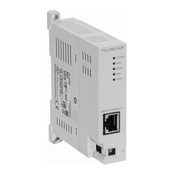
1.2 External Dimensions and Each Part Names
[2]
[3]
[4]
[5]
[1]
20.5
7 (0.28")
(0.81")
81.5 (3.21")
23 (0.91")
Unit: mm (inches)
MASS (Weight): Approx. 0.1 kg (0.22 lbs)
DIN rail mounting groove
[1]
(DIN rail: DIN46277, 35mm (1.38")
[6]
Special adapter connector
width)
1 0 B A S E - T / 1 0 0 B A S E - T X
[2]
Nameplate
[7]
connector (RJ45)
Direct mounting hole
External ground terminal (M2.5
[3]
2 holes of
4.5 (0.18")
[8]
terminal block screw)
(mounting screw: M4 screw)
[4]
Status LEDs
[9]
DIN rail mounting hook
[5]
Special adapter fixing hook
1.3 Indications of LEDs
/FX
3U
/FX
3UC
LED
LED
Status
Description
display
color
ON
Power is on
POWER
Green
OFF
Power is off
ON
100Mbps communication
100M
Green
OFF
10Mbps communication or not connected
ON
Data being sent or received.
SD/RD
Green
OFF
Data is not sent or received.
ON
Setting errors, hardware errors, etc.
ERR.
Red
Flicker
Communication errors
OFF
Setting normal, communication normal
TCP/IP: 1 or more connections are established.
ON
UDP:
1 or more connections are open.
OPEN
Green
TCP/IP: All connections are unestablished.
OFF
UDP:
All connections are closed.
2. Installation
For installation details, refer to the following manuals.
→ Refer to the FX
3U
INSTALLATION
PRECAUTIONS
• Make sure to cut off all phases of the power supply externally before
attempting installation work.
Failure to do so may cause electric shock.
INSTALLATION
PRECAUTIONS
• Use the product within the generic environment specifications described in
PLC main unit manual (Hardware Edition).
Never use the product in areas with excessive dust, oily smoke, conductive
dusts, corrosive gas (salt air, Cl
, H
S, SO
2
2
vibration or impacts, or expose it to high temperature, condensation, or rain
and wind.
If the product is used in such conditions, electric shock, fire, malfunctions,
deterioration or damage may occur.
• Do not touch the conductive parts of the product directly.
Doing so may cause device failures or malfunctions.
[6]
• Install the product securely using a DIN rail or mounting screws.
[7]
• Install the product on a flat surface.
If the mounting surface is rough, undue force will be applied to the PC board,
thereby causing nonconformities.
• When drilling screw holes or wiring, make sure that cutting and wiring debris
[8]
do not enter the ventilation slits.
[9]
Failure to do so may cause fire, equipment failures or malfunctions.
• Connect the FX
-ENET-ADP securely to special adapter connector.
3U
Loose connections may cause malfunctions.
2.1 Connection to the PLC
A connector conversion adapter is required to connect the special adapters with
FX
/FX
PLCs.
3S
3G
An expansion board is required to connect the special adapters with the FX
FX
-32MT-LT(-2) PLCs.
3UC
For installation method to PLCs, refer to the User's Manual - Hardware Edition of
the connected PLC.
Connection precautions
Only one FX
-ENET-ADP unit can be connected in the final stage (leftmost
3U
position) of the main unit, special adapter, etc.
Connect all the high-speed I/O special adapters before connecting other
special adapters when they are used in combination.
Do not connect a high-speed I/O special adapter on the left side of any
special adapters other than other high-speed I/O special adapters.
2.2 Mounting
The product is mounted by the following method.
• DIN rail mounting
• Direct mounting (mounting screw: M4 screw)
For details, refer to the User's Manual - Hardware Edition of the connected PLC.
-ENET-ADP User's Manual.
, or NO
), flammable gas,
2
2
/
3U
Advertisement
Table of Contents

Subscribe to Our Youtube Channel
Related Manuals for Mitsubishi FX3U-ENET-ADP


Summary of Contents for Mitsubishi FX3U-ENET-ADP
- Page 1 1. Outline 1.3 Indications of LEDs How to obtain manuals For product manuals or documents, consult with the Mitsubishi Electric dealer from -ENET-ADP is an Ethernet adapter for the FX who you purchased your product. Series PLC that is compliant with 100BASE-TX/10BASE-T and has the features as...
- Page 2 Category 3 or better (STP cable) power line. As a guideline, lay the control line at least 100mm (3.94") or more (2) Loss in opportunity, lost profits incurred to the user by Failures of Mitsubishi products. 4.4 Power Supply Specification away from the main circuit or power line.
- Page 3 Category 3 or better (STP cable) power line. As a guideline, lay the control line at least 100mm (3.94") or more (2) Loss in opportunity, lost profits incurred to the user by Failures of Mitsubishi products. 4.4 Power Supply Specification away from the main circuit or power line.
Need help?
Do you have a question about the FX3U-ENET-ADP and is the answer not in the manual?
Questions and answers