
Subscribe to Our Youtube Channel
Related Manuals for ATEQ F580


Summary of Contents for ATEQ F580
- Page 1 USER MANUAL ATEQ F580 Version 1.03 Factory after 2005 august 01 ATEQ F20A, F20D, 5xx Series pneumatic heads Reference: UM-18400E-U...
- Page 3 Chapters updated Up dating of the software version 1.01 > First edition UM-18400C-U 25/03 1.03, edition of the F580 only. I/O configuration mode. Evolution of the head version to 1.16, up dating the network scheme on chapter 1 Second edition...
- Page 5 • do not open the instrument when it is powered up, • avoid water spillage near of the instrument, • ATEQ is at your disposal for any further information concerning the use of the instrument under maximum safety conditions. We would like to bring to your attention that ATEQ will not be held responsible for any accident connected to the improper use of the instrument, to the work bench or to the lack of compliance with safety rules.
- Page 7 ATEQ is attached to the COFRAC and delivers a certificate following a calibration. TRAINING COURSES In the framework of partnership with our customers, ATEQ offers two types of training in order to optimise the usage and knowledge of our instruments. They are aimed at different levels of technician: •...
- Page 9 PREFACE Dear Customer, You have just purchased an ATEQ instrument, we thank you for the trust you have placed on our brand. This instrument has been designed to ensure a long and unparalleled life expectancy, and we are convinced that it will give you complete satisfaction during many long years of operation.
-
Page 11: Table Of Contents
4.2. Layout of connectors on case ....................14 4.3. Details of connectors........................14 Chapter 2 USER INTERFACES 1. APPEARANCE OF FRONT PANEL OF ATEQ F580 ...............29 2. APPEARANCE OF KEYBOARD ......................30 2.1. Validation and escape keys .......................30 2.2. Cycle keys ..........................30 3. LOCK SWITCH ..........................31 4. - Page 12 2.8. F5 to F3 interface relay board ....................153 2.9. Automatic connectors with expanding joints ................154 2.10. Filtration kit ..........................154 Chapter 6 ERROR MESSAGES 1. ERROR FOR THE CENTRAL ......................155 2. ERROR FOR ONE HEAD........................156 UM-18400E-U ATEQ F580 User manual Page 2/168...
- Page 13 1. TECHNICAL CHARACTERISTICS ....................161 2. DEFINITION DRAWING OF MECHANICAL PARTS..............162 2.1. F580 control unit ........................162 2.2. Pneumatic heads ........................163 3. CONVERSION TABLE ........................164 4. PARAMETERS STORED ........................165 5. VALVES CODES USED IN YOUR APPLICATION ................166 Index UM-18400E-U ATEQ F580 User manual Page 3/168...
- Page 14 Table of contents UM-18400E-U ATEQ F580 User manual Page 4/168...
-
Page 15: Preamble
PREAMBLE 1. DEFINITION OF THE ATEQ F580 The ATEQ F580 is a compact air/air leak detector used to control the air-tightness of parts on production lines. It is especially adapted to manual and semi-automatic workbenches. The method used is based on the measurement of a small variation or drop in differential pressure between both the test and reference parts, when both are filled with an identical pressure. -
Page 16: Measurement Characteristics
50 kPa to 500 kPa 50 kPa to 800 kPa 100 kPa to 1000 kPa 50 kPa to 1600 kPa 100 kPa to 1600 kPa 100 kPa to 2000 kPa For other specific pressures please contact ATEQ. UM-18400E-U ATEQ F580 User manual Page 6/168... -
Page 17: The Main Types Of Measurements
After filling the test and reference parts with the required level of pressure, the instrument measures the differential pressure between the two volumes, which, are separated by the equalisation valve. At the end of a cycle, the ATEQ empties the components via the dump valve. 3.2. I NDIRECT... -
Page 18: The Three Types Of Test
This method is also used for distortable parts and parts with a constant temperature which is different to the TEST PART ambient temperature. The central naught test offers a considerable time advantage (two parts tested simultaneously). UM-18400E-U ATEQ F580 User manual Page 8/168... -
Page 19: Direct Measurement, Pressurisation
Pressurisation of the test and reference parts. At the end of the fill time, The fill time the ATEQ instrument controls the test pressure, if this is not correct, it will signal a test pressure error. Test and reference parts are completely cut off from the air supply, but are pressurised to the test pressure level. -
Page 20: Symbols Presentation
Dry contact output. Input Dry contact input. Infrared link, at this place there's the receiver and Infrared link transmitter of the infrared link. Analogue Analogue output. output Analogue Analogue input for the temperature sensor. input UM-18400E-U ATEQ F580 User manual Page 10/168... -
Page 21: Chapter 1 Installation Of The Instrument
C ON D ITIONS D' E P R E U V E RESULTAT The ATEQ F580 is supplied in a 19" case. The instrument operates at a voltage of 90 to 260 V AC and is supplied with a power cable. -
Page 22: Basics Recommendations
WARNING CONCERNING THIS USER MANUAL The various possibilities of wiring networks described in this user manual are valid only for the instruments produced after: 2005 august 1st UM-18400E-U ATEQ F580 User manual Page 12/168... -
Page 23: Installation And Cabling
24 V DC Male network Female network cap CENTRAL HEAD HEAD HEAD HEAD MODULE N° 3 N° 4 N° 1 N° 2 24 V DC 24 V DC 24 V DC 24 V DC UM-18400E-U ATEQ F580 User manual Page 13/168... -
Page 24: Installation Of The Ateq F580
Chapter 1 – Installation of the instrument 4. INSTALLATION OF THE ATEQ F580 4.1. S TART TOP SWITCH ⇒ I : start ⇒ 0 : stop 4.2. L AYOUT OF CONNECTORS ON CASE 4.3. D ETAILS OF CONNECTORS 4.3.1. Electrical power supply ⇒... - Page 25 Pin 2 RXD Data reception Broche 7 RTS request to send Pin 3 TXD Data emission Broche 8 CTS clear to send Pin 4 Not used Broche 9 Not used Pin 5 Ground UM-18400E-U ATEQ F580 User manual Page 15/168...
- Page 26 In the event of Winateq network management, this button allows the confirmation of the centrals’ presence in the network. 4.3.6. Head "PIN service" button This button allows the confirmation of the heads' presence in tne network in the hoped order. UM-18400E-U ATEQ F580 User manual Page 16/168...
- Page 27 When the instrument is considered as the first or the last element of the network, it must have terminations resistors in the cable connector. The cable supplied by ATEQ has the resistors on each connector and can be used on a configuration with only 2 instruments: a master and a slave.
- Page 28 This mode is useful if the number of measurement units is much greater than the number of I/O modules or to limit the number of I/O modules. Note: in standard or compact mode a START without unit selection starts all the units. UM-18400E-U ATEQ F580 User manual Page 18/168...
- Page 29 (input 10) (input 11) (input 12) (input 13) (input 14) Prgm select 17 Prgm select 33 With x who takes the 0 or 1 value in function of the program number to be called. UM-18400E-U ATEQ F580 User manual Page 19/168...
- Page 30 (input 7) (input 8) (input 9) (input 10) (input 11) Program selection 17 Program selection 33 With x who takes the 0 or 1 value in function of the program number to be called. UM-18400E-U ATEQ F580 User manual Page 20/168...
- Page 31 0,5 s after the end of the impulse. t = 0,5 sec minimum In the above example it be considered that all the inputs not listed are standing UM-18400C-U ATEQ F580 User manual Page 21/168...
- Page 32 COMMON (analogue output 1) ANALOGUE OUTPUTS PIN 15 Analogue output n°2 PIN 16 COMMON (analogue output 2) * Options. Charge / Load 24 V DC 0,1 A max Obligatory diode for an inductive load. UM-18400E-U ATEQ F580 User manual Page 22/168...
- Page 33 2 + alarm Output 5 Output 5 Fin de cycle Fin de cycle The compact mode is a software function which is activated in the CONFIGURATION / CHANGE I/O / OUTPUT menu. UM-18400E-U ATEQ F580 User manual Page 23/168...
- Page 34 Fail part sealed component learn request. Calibration check by volume request. Custom unit learn request. Custom unit check request. ATR learning cycle request. Volume calculation request. Some possibilities appear only if the function is used. UM-18400E-U ATEQ F580 User manual Page 24/168...
- Page 35 2 and 4 pins on the J3 + 24 V DC (Programmable input) connector too. Common Good part INPUTS Test fail part NPN MODE Reference fail part Alarm End of cycle Ground UM-18400E-U ATEQ F580 User manual Page 25/168...
- Page 36 2 and 4 pins on the J3 connector too. (Programmable input) Common 0,2 A Good part 0,3 A Max Test fail part with ATEQ 24 V DC Reference fail part Alarm 0,2 A End of cycle Ground UM-18400E-U ATEQ F580 User manual Page 26/168...
- Page 37 4.3.14. 3) Pneumatic inputs/outputs ⇒ Reference output. ⇒ Pressurisation output. ⇒ Test output. These outputs are for connection of parts (test, reference). The pressurisation output is used for the addition of ATEQ accessories (Y valve). UM-18400E-U ATEQ F580 User manual Page 27/168...
- Page 38 100 kPa (1 bar) greater than test pressure with a minimum of 400 kPa (4 bar). When an electronic regulator is used, the regulator input pressure must be at least 10 % greater than full scale value of the electronic regulator + 100 kPa (+ 1 bar). UM-18400E-U ATEQ F580 User manual Page 28/168...
-
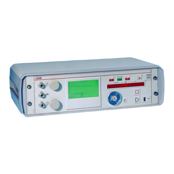
Page 39: Appearance Of Front Panel Of Ateq F580
Chapter 2 – User interfaces Chapter 2 USER INTERFACES 1. APPEARANCE OF FRONT PANEL OF ATEQ F580 16 lines display Pressure Results 14 character regulators display LED display F580 C OND ITION S D ' E P R E U V E... -
Page 40: Appearance Of Keyboard
Movement of the comer to the left when setting numerical values. Movement across to the right in the central module main menu. Movement of the comer to the right when setting numerical values. UM-18400E-U ATEQ F580 User manual Page 30/168... -
Page 41: Lock Switch
LOCKED position No access to adjustable parameters ACCESS position. Access to adjustable parameters Note : it is possible to start and stop test cycles whatever the position of the lock switch (LOCKED or ACCES). UM-18400E-U ATEQ F580 User manual Page 31/168... -
Page 42: Displays And Lights
EANINGS OF INDICATOR LIGHTS symbol indicates a lit indicator light. Example for a pneumatic type head. Pass indicator light Test Part Fail indicator light Reference Part Fail indicator light Alarm (indicator light flashing) UM-18400E-U ATEQ F580 User manual Page 32/168... -
Page 43: Infrared Interface
ATEQ Leak flow calibrator. This connector is not part of the measurement circuit and does not interfere with the test. - Page 44 Chapter 2 – User interfaces UM-18400E-U ATEQ F580 User manual Page 34/168...
-
Page 45: Chapter 3 Start-Up And Settings
STARTUP indicates the level of completion of the start-up. M A I N M E N U CONFIG Then displays the main menu, the PARAMETERS SERVICE instrument is ready. DISPLAY RESULTS 10:57:22 18/06/2002 UM-18400E-U ATEQ F580 User manual Page 35/168... -
Page 46: Start-Up Of The Network
Use the navigation keys to move the INSTALL LANGUAGE : ENGLISH cursor till it is in front of the PRINTER "INSTALLATION" menu then confirm HOUR BACKLIGHT with ENTER. HEAD NAME HEAD 01 : F5 10:59:32 18/06/2002 UM-18400E-U ATEQ F580 User manual Page 36/168... - Page 47 HEAD : 02 I/O MODULES : 01 "CONFIGURATION" menu. Return to IDENTIFICATION the main menu to carry out test cycles. I/O MODE : EXTENDED I/O DISTRIBUTION LANGUAGE : ENGLISH 11:08:13 18/06/2002 UM-18400E-U ATEQ F580 User manual Page 37/168...
-
Page 48: Allocation Of The Outputs
Note: the "Extended", "Standard" and "Compact" modes also concern the J8 inputs connector. The measurement unit and number selection modes are different depending on the chosen mode. Refer to chapter 1, paragraph 4.3.10 "J8 inputs connector". UM-18400E-U ATEQ F580 User manual Page 38/168... -
Page 49: Allocation Of The Modules
OUTPUTS 1 : HEAD 02 module required, confirm when the MODULE 1 OUTPUTS 2 : HEAD 01 selection is made. MODULE 1 OUTPUTS 3 : HEAD 03 MODULE 1 OUTPUTS 4 : HEAD 04 UM-18400E-U ATEQ F580 User manual Page 39/168... -
Page 50: Management Of The Measurement Units
HEAD 01 :F5 unit are displayed, next, select the Pr:04 D MODE HEAD 02 :F5 Pr:05 OPERATOR program to be modified and confirm Pr:06 ---------- with the "ENTER" key. Pr:07 ---------- Pr:08 ---------- 11:03:25 24/07/2002 UM-18400E-U ATEQ F580 User manual Page 40/168... - Page 51 TRANSIENT ABSORB. 2 : NO PRE-FILL : NO The functions must be activated in FILL MODE : NO VALVES CODES : NO the "CONFIGURATION" menu to END CYCLE : NO appear in the "FUNCTIONS" menu. 15:39:59 20/08/2002 UM-18400E-U ATEQ F580 User manual Page 41/168...
-
Page 52: Creation Of A Test Program
Pr:08 ---------- 11:03:25 24/07/2002 P A R A M E T E R S PARAMETERS FUNCTIONS Copy-Paste Next, access the parameters, the functions or carry out a copy-paste operation to another program. 11:10:01 24/07/2002 UM-18400E-U ATEQ F580 User manual Page 42/168... - Page 53 : NO appear in the "FUNCTION" menu. 15:39:59 20/08/2002 Note: when a parameter is modified, it is possible to move the comer to unit, ten, hundred, etc. by using the left and right arrows. UM-18400E-U ATEQ F580 User manual Page 43/168...
-
Page 54: Test Type Selection
The choice of working in Pa or in Pa/s depends on the application. In all events, it must not be forgotten that the full scale of the sensor in Pa or Pa/s is limited to 50 or 500 Pa depending on the instrument configuration. UM-18400E-U ATEQ F580 User manual Page 44/168... - Page 55 This type of test means that the operator can carry out operations on the part whilst under test, then to confirm these operation using a "START" key if the operator test is good, or "RESET" key if the test is fail. UM-18400E-U ATEQ F580 User manual Page 45/168...
-
Page 56: Parameter Settings
COUPLING A : 02.0 FILL : 01.0 with the ENTER key. STABILISATION : 00.5 TEST : 01.0 DUMP : 00.5 PRESSURE UNIT : bar Max. FILL : 10.0 Min. FILL : 0.000 15:49:53 20/08/2002 UM-18400E-U ATEQ F580 User manual Page 46/168... - Page 57 Too Long (TTLR), then to shorten it until a drop in pressure occurs due to thermal effects. Determine the TTLR by using the following formula: TTLR volume test pressure mbar Carry out a cycle. When the instrument switches to the stabilisation period, the pressure must remain stable. UM-18400E-U ATEQ F580 User manual Page 47/168...
- Page 58 This indicates that the stabilisation time has become too short. Increase it slightly. Set this parameter using the method described in § 4.4. UM-18400E-U ATEQ F580 User manual Page 48/168...
- Page 59 Simply set the test pressure value and the instrument adjusts it automatically. This function can be used with a mechanical regulator (regulator with an adjustable knob) or an electronic regulator (no adjustment). UM-18400E-U ATEQ F580 User manual Page 49/168...
- Page 60 CONFIGURATION menu and then the EXTENDED MENU. If no additional parameters are confirmed in the EXTENDED MENUS, the FUNCTION menu will be empty when selected. To activate these parameters, refer to chapter 4 § 2.2. UM-18400E-U ATEQ F580 User manual Page 50/168...
-
Page 61: Duplication Of A Test Program
LEAK TEST Pr:04 ---------- Pr:05 ---------- Confirm with the ENTER key. Pr:06 ---------- The program is instantly copied. 16:54:56 20/08/2002 Press several times on the C key to return to the main menu. UM-18400E-U ATEQ F580 User manual Page 51/168... -
Page 62: Deleting A Test Program
15:50:15 20/08/2002 The list of the available test types is ---------- displayed, select the "---------" line and LEAK TEST BLOCKAGE confirm with the ENTER key. D MODE OPERATOR The program selected is deleted. UM-18400E-U ATEQ F580 User manual Page 52/168... -
Page 63: Launching A Cycle
: YES HEAD 2 : YES a "YES". COMPACT : NO RESULTS : NO Next, confirm with a "YES" the unit(s) CURVE : YES LED DISPLAY : NO displayed on the screen. 09:19:36 21/08/2002 UM-18400E-U ATEQ F580 User manual Page 53/168... -
Page 64: Choice Of The Measurement Unit Program
Return to the main menu by pressing several times on the key. Note: it is possible to start all the measurement units at the same time by pressing on the start key in a previous menu. UM-18400E-U ATEQ F580 User manual Page 54/168... -
Page 65: Launch Of A Special Cycle
All the special cycles available are Regulator adjust 2 displayed, place the cursor in front of Infinite fill Piezo auto zero the special cycle required (here, "Regulator adjust. 1") and confirm. 17:41:07 11/07/2002 UM-18400E-U ATEQ F580 User manual Page 55/168... - Page 66 R U N / P r : 0 0 1 P R E S S 2 . 0 0 b a r L E A K 0 0 8 R E A D Y ( O K ) UM-18400E-U ATEQ F580 User manual Page 56/168...
-
Page 67: Adjustment Of The Test Pressure
H 0 2 - - - - test. R U N / P r : 0 0 1 P R E S S 2 . 0 0 b a r R E A D Y UM-18400E-U ATEQ F580 User manual Page 57/168... -
Page 68: Instruction Adjustment With Mechanical Regulator
PASTE : HEAD 00 : --- Pr:03 LEAK TEST HEAD 01 :F5 Pr:04 OPERATOR HEAD 02 :F5 Pr:05 ---------- and validate with the "ENTER" key. Pr:06 ---------- Pr:07 ---------- Pr:08 ---------- 11:03:25 24/07/2002 UM-18400E-U ATEQ F580 User manual Page 58/168... - Page 69 11:14:12 24/07/2002 Launch a regulator setting special cycle. Turn the regulator wheel to pressurise. Take the pressure value above the target point. UM-18400E-U ATEQ F580 User manual Page 59/168...
-
Page 70: Setting A Filling Instruction With An Electronic Regulator
(1 bar) greater than test pressure. 10. STOPPING A CYCLE Press the RESET key to stop the measurement in progress. The instrument is stopping his cycle and configured for a new measurement test. UM-18400E-U ATEQ F580 User manual Page 60/168... -
Page 71: Chapter 4 Functions Of The Instrument
The functions regarding the Functions > head* measurement are displayed Copy-Paste programs > Central DISPLAY Standard > Yes/No > Head* number Compact > Yes/No > Head* number Results > Yes/No > Head* number UM-18400E-U ATEQ F580 User manual Page 61/168... - Page 72 > 8bit-sans > 1 8bit-="0" > 1 8bit-="1" > 1 8bit-paire > 1 8bit-impaire Head* selection > Head* number > Yes/No Hour > Hour Minute Month Year Backlight > Mode > Continuous Manual UM-18400E-U ATEQ F580 User manual Page 62/168...
- Page 73 Note: the parameters which appear in EXTENDED MENUS will be found in the FUNCTIONS menu when they are activated. * A head is a single measurement unit (one instrument can contain more than one head/measurement unit such as an F580). UM-18400E-U ATEQ F580 User manual Page 63/168...
-
Page 74: Run Menu
Depending on the position in the menus, the test program (or special cycle) is started on the measurement unit, or on all the measurement units selected in the "START KEY" menu. Refer to chapter 3, paragraph 7 "Launching a cycle". UM-18400E-U ATEQ F580 User manual Page 64/168... -
Page 75: Parameters Menu
To manage the test cycles inside a measurement unit, refer to its user manual. When entering the "HEAD XX" menu, after having chosen the program number, it is possible to modify the set of parameters of the program for the chosen unit. UM-18400E-U ATEQ F580 User manual Page 65/168... -
Page 76: Display Menu
R U N / P r : 0 0 1 P R E S S 2 . 0 0 b a r L E A K 0 0 4 P a R E A D Y ( O K ) UM-18400E-U ATEQ F580 User manual Page 66/168... - Page 77 H 0 2 0 1 ( O K ) 0 1 2 P a 2 0 0 . 4 m b a r 1 1 : 5 6 : 5 7 0 1 / 0 7 / 2 0 0 2 UM-18400E-U ATEQ F580 User manual Page 67/168...
- Page 78 "C" key before pressing on the "START" key A curve is then displayed live. To the Note: thresholds placed right is an example of the pressure automatically depending on the reject levels. sensor display. UM-18400E-U ATEQ F580 User manual Page 68/168...
- Page 79 The LED display shows the state of a test part, good, bad in test or reference, as well as alarms. For the text and indicator displays refer to the user manuals of the measurement units concerned. READY 14 character L.E.D. display: Results and warning indicators: UM-18400E-U ATEQ F580 User manual Page 69/168...
-
Page 80: Configuration Menu
: 01 I/O MODULES : 01 between the three modes and confirm. I/O MODE : ETENDU See chapter 3, paragraph 3 "Allocation I/O DISTRIBUTION IDENTIFICATION of the outputs". LANGUAGE : ENGLISH 11:08:13 18/06/2002 UM-18400E-U ATEQ F580 User manual Page 70/168... - Page 81 INSTALL Access to the "LANGUAGE" menu and FRANCAIS HEAD : 02 modification of the language if I/O MODULES : 01 IDENTIFICATION necessary. I/O MODE : EXTENDED I/O DISTRIBUTION LANGUAGE : ENGLISH 11:06:45 18/06/2002 UM-18400E-U ATEQ F580 User manual Page 71/168...
- Page 82 (rear panel connectors). In these three modes, the intensity of the light is programmable from 0 % (screen off) up to 100 % (maximum light intensity). UM-18400E-U ATEQ F580 User manual Page 72/168...
- Page 83 Note: maximum number of characters for the name of a unit: 13. 1.5.7. "HEAD XX" menu This menu accesses the configuration and extended menus of the measurement units. For more information refer to the user manual for the measurement unit concerned. UM-18400E-U ATEQ F580 User manual Page 73/168...
-
Page 84: Service Menu
This menu only appears when the key is in the "ACCESS" position. DELETE menu: allows the deletion of all the parameters. RECOVERY menu: allows the recovery of all the parameters. SAVE menu: allows the saving of all the parameters. UM-18400E-U ATEQ F580 User manual Page 74/168... - Page 85 P R O P E R T I E S HEAD 01 The properties and characteristics of ATEQ F5 the measurement unit (head) are Version 01.15c 0-> 5000 mbar displayed. Diff. F. Sc. 500 Pa UM-18400E-U ATEQ F580 User manual Page 75/168...
- Page 86 This menu allows the display the status of the J7 (all or nothing outputs) and J8 (inputs) connector inputs and outputs. I / O S T A T U S INPUTS OUTPUTS Enter the "I/O STATUS" menu. The validated outputs and inputs are represented by a black rectangle. UM-18400E-U ATEQ F580 User manual Page 76/168...
- Page 87 The "ADD" menu then appears in the list. In the event of a definitive deletion of a measurement unit, you must reinitiate the network and identify the measurement units (heads) one by one, refer to paragraph 1.5.1.1) "Installation menu". UM-18400E-U ATEQ F580 User manual Page 77/168...
- Page 88 HEAD 01 : F5 : HEADX1 HEAD02 :F5 HEAD 02 : F5 : HEADX2 HEAD03 :I/O PARAMETERS Next, select the measurement unit NETWORK (head) to be added in the network. PROPERTIES NETWORK STATUS REMOVE 09:54:02 02/07/2002 UM-18400E-U ATEQ F580 User manual Page 78/168...
- Page 89 REPLACE transferring the parameters, the WITHOUT PARA. parameters of the new unit are WITH PARA. REMOVE conserved or they must entered if they have not been created 16:38:21 24/07/2002 UM-18400E-U ATEQ F580 User manual Page 79/168...
- Page 90 (head), The network is then ready REPLACE again. WITHOUT PARA. WITH PARA. REMOVE 16:41:56 24/07/2002 Switch off the instrument, or ensure that it is switched off. Physically remove the replaced head from the network (cabling). UM-18400E-U ATEQ F580 User manual Page 80/168...
-
Page 91: Results Menu
051 Pa 1.99 bar connected to the central. H02 01 (OK)° 000 Pa 798.7 mbar H01 01 (OK)° 048 Pa 1.99 bar RESET: to definitively erase the results displayed on the screen. 15:33:32 08/07/2002 UM-18400E-U ATEQ F580 User manual Page 81/168... -
Page 92: F5 Head
Coupling time A Reset program Fill time Dump time Bar > MPa > kPa Pressure unit > > Pa > PSI > mbar Maximum fill Minimum fill Set fill instruction Functions > Refer to note UM-18400E-U ATEQ F580 User manual Page 82/168... - Page 93 Regulator 2 adjust Infinite fill Piezo auto zero ATR learning Volume compute Custom unit learn Custom unit check Verify + custom unit learn Check test result Sealed PASS part learn Sealed FAIL part learn UM-18400E-U ATEQ F580 User manual Page 83/168...
- Page 94 > None regulator Regulator 1 Regulator 2 Regulator control Automatic External Number of Auto piezo reset > yes / no > minutes Number de cycles Pa, PSI, mbar, Pressure unit > bar, Mpa,kPa UM-18400E-U ATEQ F580 User manual Page 84/168...
- Page 95 Date & time Lines before Lines after Inter line Form feed Send conditions > All results Pass Test fail Reference fail Alarm Pressure out Re-workable Calibration Export > yes / no Print parameters UM-18400E-U ATEQ F580 User manual Page 85/168...
- Page 96 External dump > yes / no > Normally open Normally Closed Program Change I/O > Input 7 > selection Pressure 1 regulator 1 adjust Pressure 1 regulator 2 adjust Pressure 2 sensor test UM-18400E-U ATEQ F580 User manual Page 86/168...
- Page 97 Verify + custom unit Sealed PASS part learn Sealed FAIL part learn Start Auto parameters > Yes / No > % of test SERVICE > PARAMETERS > Save Restore Reset SPECIAL > Yes/No CYCLES UM-18400E-U ATEQ F580 User manual Page 87/168...
- Page 98 Start time > Hour Minute Stop time > Hour Minute Delay Note: the parameters which are in the EXTENDED MENUS can be found in the FUNCTIONS menu of a program when they are activated. UM-18400E-U ATEQ F580 User manual Page 88/168...
- Page 99 % drift Check time ATR 0 > ATR 1 > > Start ATR 2 Transient % drift Pre-fill > Pre-fill type > Standard > Maximum pre-fill Set pre-fill instruction Pre-fill time Pre-dump time UM-18400E-U ATEQ F580 User manual Page 89/168...
- Page 100 End of Cycle > Automatic reset Dump + Reset Fill time Double reset Blow mode > Regulator > Regulator 1 Regulator 2 Differential auto- Mini valve > zero Rework limits > Test rework Reference rework UM-18400E-U ATEQ F580 User manual Page 90/168...
- Page 101 Yes/no Reference Reference > volume volume External dump > Yes/no Temperature Correction > Yes/no > correction 1 percentage Test time Indirect > Piezo reset > Yes/no Maximum fill Minimum fill Sign > Yes/no UM-18400E-U ATEQ F580 User manual Page 91/168...
-
Page 102: Configuration Menu
"YES". When it's validating, FILL MODE : NO END CYCLE : NO the functions appears in the MINI-VALVE : NO "FUNCTIONS" menu of the parameters. RECUP. THRESHOLD : NO REFERENCE VOLUME : YES 01/07/2002 11:26:18 UM-18400E-U ATEQ F580 User manual Page 92/168... - Page 103 PASS (part good), TEST FAIL (test part bad), REFERENCE FAIL (reference part bad), ALARM, PRESSURE OUT (pressure error), REWORKABLE (parts which can be repaired), CALIBRATION (calibration error). Select the option and enter settings if necessary. UM-18400E-U ATEQ F580 User manual Page 93/168...
- Page 104 They remain active throughout all cycles between the first and last program in the chain. The various waiting times A are applied in the programs in between. Associated parameters to be set: WAIT A, WAIT B. Select the option and enter settings if necessary. UM-18400E-U ATEQ F580 User manual Page 94/168...
- Page 105 To avoid any influence, a solution is to increase the stabilisation time to obtain the ideal test time measurement conditions. However increasing the stabilisation time for each test does not suit a normal production frequency. UM-18400E-U ATEQ F580 User manual Page 95/168...
- Page 106 ∆ P1 ∆ P2 possible leakage of the part is taken into account when the transient value determined during the special Fill Stab Test1 Wait 5 x test time Test2 Dump Time cycle. UM-18400E-U ATEQ F580 User manual Page 96/168...
- Page 107 Chapter 4 – Functions of the instrument At the end of test time 1, the ATEQ measures the pressure variation ∆P1, depending on the transient and the leak if it is present. ∆P1 = Leak + Transient Following the waiting time (equivalent to 5 times the test time), we consider that the transient effects have disappeared.
- Page 108 "pre reg. adjust" special cycle then set the associated parameters. With an electronic regulator Simply set the associated parameters. Associated parameters to be set: Max P-FILL (maximum pre-fill pressure limit), Pre- FILL (pre-fill time), Pre-DUMP (pre-dump time). UM-18400E-U ATEQ F580 User manual Page 98/168...
- Page 109 The user sets a target value for the fill pressure and opens the regulator to full flow. When the target pressure is reached, the air supply cuts off automatically. Associated parameters to be set: I. FILL (fill target). UM-18400E-U ATEQ F580 User manual Page 99/168...
- Page 110 1 paragraph 4.3.12. Associated parameters to be set: External 1, External 2, External 4, External 5, External 6, Internal 1, Internal 2. Select the option and enter settings if necessary. EXTERNALS EXTERNES INTERNALS INTERNES UM-18400E-U ATEQ F580 User manual Page 100/168...
- Page 111 Associated parameters to be adjusted: Auxiliary 1, Auxiliary 2, Auxiliary 3, Auxiliary 4. Select the option and enter settings if necessary. AUTO J1 + 24 V Aux 4 Aux 3 AUX J10 + 24 V Aux 1 Aux 2 UM-18400E-U ATEQ F580 User manual Page 101/168...
- Page 112 • Relay sequencing related to different cycle ends In order to interface the ATEQ F510 and F520 with its environment (PLC, PC …), the following timing charts supply the details of the sequencing of the electrical outputs (relay board on the J3 connector) and pneumatic outputs (automatic connectors), depending on the commands entered on the front panel or through the J3 connector (START, RESET).
- Page 113 This selection can only be modified during the inter cycle period. To return to program 1, when a cycle is not in progress, press any of the program selection inputs. UM-18400E-U ATEQ F580 User manual Page 103/168...
- Page 114 This selection can only be modified during the inter cycle period. To return to program 1, when a cycle is not in progress, press any of the program selection inputs. UM-18400E-U ATEQ F580 User manual Page 104/168...
- Page 115 This selection can only be modified during the inter cycle period. To return to program 1, when a cycle is not in progress, press any of the program selection inputs. UM-18400E-U ATEQ F580 User manual Page 105/168...
- Page 116 PRESSURE t mini START t mini Reset program t mini number Active automatic B time Connector A Inactive Active automatic B time Connector B Inactive Fail part End of cycle UM-18400E-U ATEQ F580 User manual Page 106/168...
- Page 117 This selection can only be modified during the inter cycle period. To return to program 1, when a cycle is not in progress, press any of the program selection inputs. UM-18400E-U ATEQ F580 User manual Page 107/168...
- Page 118 ) and has a base time of 0.01s instead of 0.1 s. Programming for the ATEQ F5 with mini valve is identical to that for the standard ATEQ F5 . Parameters to be set are: A-Z Diff (differential Auto Zero).
- Page 119 Volume fill ELECTRONIC REGULATOR FILL VALVE TRANSDUCER The internal pneumatic circuit (if required, an external volume can be added) of the ATEQ F510 or F520 (V1) REGULATOR is filled to a pressure P1. EXTERNAL VOLUME connected to the pressurisation DUMP VALVE...
- Page 120 • Test modes The ATEQ F510 or F520 for sealed components can carry out the following tests: 1. Only the large leak test, 2. The large leak test, then the small leak test at a weaker final pressure These two modes can be programmed from the instrument's front panel and are called: •...
- Page 121 See paragraph 3.3.8. "Sealed component learning". Select the option and enter settings if necessary. Test cycles can not be carried out unless learning cycles have previously been carried out. UM-18400E-U ATEQ F580 User manual Page 111/168...
- Page 122 (the greatest leak) recorded during the test and displays the result. LEAK ∆P/∆t MAXIMAL VALUE MEASURED TIME ∆ ∆ Note: Peak measurement mode only works in t and excludes the use of ATR mode. UM-18400E-U ATEQ F580 User manual Page 112/168...
- Page 123 Run a special "Regulator" cycle to set the test pressure for the known standard leak (see § 3.3.1 "Regulator adjust special cycle"). Carry out the special "Volume calculation" cycle by giving the leak value. The value of the volume is updated within the program. UM-18400E-U ATEQ F580 User manual Page 113/168...
- Page 124 The percentage of the variation to be taken into account. Example: a pressure variation of 15 Pa during 2 test seconds, with a percentage of 60 %, will apply a correction of 9 Pa on each test result. UM-18400E-U ATEQ F580 User manual Page 114/168...
- Page 125 The pressure monitoring is PIEZO carried out by two electrical SENSOR 2 TEST piezo sensors. PART REGULATOR 1 PIEZO SENSOR 1 EXTERNAL FILL VALVE P ≥ 16 BAR EXTERNAL REGUALTOR UM-18400E-U ATEQ F580 User manual Page 115/168...
- Page 126 R U N / P r : 0 0 1 P R E S S 2 . 0 0 b a r above example, on the head 1). R E A D Y UM-18400E-U ATEQ F580 User manual Page 116/168...
- Page 127 2.2.3. Electronic regulator The ELECTRONIC REGUALTOR function appears when one or two electronic regulators are installed in the instrument. This function enables the shutting off of one or both regulators if they are not required. UM-18400E-U ATEQ F580 User manual Page 117/168...
- Page 128 Note: the two options can be set, in this case the first counter to expire will launch the auto-zero, both counters will then be reset. Select the option and enter settings if necessary. UM-18400E-U ATEQ F580 User manual Page 118/168...
- Page 129 Prog. name (Display of the program name when set), Date & Time (printing of the date and the time), Lines before (number of lines before the result), Lines after (number of lines after the result), Inter line (space between each line), Form feed (new page). UM-18400E-U ATEQ F580 User manual Page 119/168...
- Page 130 < 0 0 > : A L : P R E S S U R E L O W < 0 0 > : A L : P R E S S U R E H I G H UM-18400E-U ATEQ F580 User manual Page 120/168...
- Page 131 This frame is operated by connecting a computer to the instrument's RS 232 link. Select the option and enter settings if necessary. 2.2.8. 5) Print parameters By confirming this function, the test parameters of the activated programs are instantly printed. UM-18400E-U ATEQ F580 User manual Page 121/168...
- Page 132 Note: The "PROGRAM NAME" characters are printed when a program name has been set in the parameters. 2.2.9. RS485 This function enables the configuration of the RS485 output to a C540 central or F580 when the instrument is installed in a network. Select the option and enter settings if necessary.
- Page 133 EXTERNAL DUMP : YES EXTERNAL DUMP : NORMALLY CLOSED LIGHT 06/11/2002 13:35:52 If the instrument is fitted with this option, internal and external valve codes 2 are no longer available. UM-18400E-U ATEQ F580 User manual Page 123/168...
- Page 134 The compact mode enables the output of test results for two sequenced cycles maximum. Outputs 1 and 2 are reserved to the first cycle, outputs 3 and 4 to the second, output 5 for the general cycle end. UM-18400E-U ATEQ F580 User manual Page 124/168...
-
Page 135: Special Cycles Menu
This cycle is used to enter the ATR parameters if they are not known. This should be done after ATR learning: each start-up of the instrument, or after a long period with no test cycles. UM-18400E-U ATEQ F580 User manual Page 125/168... - Page 136 The starting of the special cycle is only done in the measurement unit selected, otherwise the start will concern al the measurement units by pressing on the before the starting of the cycle. UM-18400E-U ATEQ F580 User manual Page 126/168...
-
Page 137: Available Service Special Cycles
To run a special cycle, select it in the Special Cycles menu, then press the button. To stop it, press the button. In some cycles the stop is automatic. UM-18400E-U ATEQ F580 User manual Page 127/168... -
Page 138: Start Special Cycles
H 0 2 - - - - test. R U N / P r : 0 0 1 P R E S S 2 . 0 0 b a r R E A D Y UM-18400E-U ATEQ F580 User manual Page 128/168... - Page 139 It is however possible to manually adjust this parameter to return it to the best possible value for the pressure monitoring. UM-18400E-U ATEQ F580 User manual Page 129/168...
- Page 140 H 0 2 - - - - R U N / P r : 0 0 1 P R E S S 2 . 0 0 b a r R E A D Y UM-18400E-U ATEQ F580 User manual Page 130/168...
- Page 141 "NO" LIGHT 06/11/2002 13:31:11 Attention: If an auto zero cycle is not carried out regularly, measurement errors may occur and result in false readings for the air tightness of parts. UM-18400E-U ATEQ F580 User manual Page 131/168...
- Page 142 : during the auto zero cycle, only the cycle start is memorised. 3.3.4. Piezo reset cycle planner START Piezo 5 min 5 min 5 min reset > 3 sec < 3 sec > 3 sec End of test cycle test cycle test cycle cycle UM-18400E-U ATEQ F580 User manual Page 132/168...
- Page 143 The value of the volume Max. FILL : 01.2 calculated is entered in the current Min. FILL : 00.8 program parameters. REJECT UNIT : cm3/mn REJECT CALCULATION : Pa VOLUME : 0.067 17:58:24 06/11/2002 UM-18400E-U ATEQ F580 User manual Page 133/168...
- Page 144 The display gives the result of the test in the calibration unit. Note: The CDF (leak flow calibrator) can be used to calibrate the instrument and to send this value via the infra-red link. UM-18400E-U ATEQ F580 User manual Page 134/168...
- Page 145 The custom unit check + Custom unit learn cycle request can be carried out on input 7 of the J3 which has been programmed for this function or on a pre programmed key on the optional RC5 consol if it is installed. UM-18400E-U ATEQ F580 User manual Page 135/168...
- Page 146 : YES REJECT UNITS : Cal-Pa CAL DRIFT : 000 The Custom name can be deleted in the NAME PARAMETERS/ UNITS menu and Delete CAL name select the Delete CAL name line. 16:29:12 02/10/2003 UM-18400E-U ATEQ F580 User manual Page 136/168...
- Page 147 Once the cycle id finished, the sealed component values are saved. Proceed in the same way for the bad part parameters. For further information about sealed components, see paragraph 2.2.1.3) s) in this chapter. UM-18400E-U ATEQ F580 User manual Page 137/168...
- Page 148 The instrument carries out a test cycle and then continues the cycle by carrying out a learning cycle. Once the cycle is finished, the transient values are saved. UM-18400E-U ATEQ F580 User manual Page 138/168...
-
Page 149: Starting The Service Special Cycles
Note: in an electronic regulator is used, P R E S S 2 . 0 0 b a r the adjustment of the instruction can be R E A D Y modified with the up and down arrows. UM-18400E-U ATEQ F580 User manual Page 139/168... - Page 150 H 0 2 - - - - R U N / P r : 0 0 1 P R E S S 2 . 0 0 b a r R E A D Y UM-18400E-U ATEQ F580 User manual Page 140/168...
- Page 151 - - - - displays PART PASS. R U N / P r : 0 0 1 P R E S S 2 . 0 0 b a r R E A D Y UM-18400E-U ATEQ F580 User manual Page 141/168...
- Page 152 T 0 2 - - - - C Y C L E / P r : 0 0 1 P R E S S 2 . 0 0 b a r P R E T UM-18400E-U ATEQ F580 User manual Page 142/168...
-
Page 153: Accessories
Chapter 5 - Accessories Chapter 5 ACCESSORIES 1. ACCESSORIES SUPPLIED WITH THE INSTRUMENT 1.1. P OWER SUPPLY CABLE The cable is used for connection to the electrical network (from 90 to 260V AC). UM-18400E-U ATEQ F580 User manual Page 143/168... -
Page 154: Optional Accessories
To check that the leak has not been blocked, attach a piece of flexible tubing to its extremity and submerge this in water to watch for bubbles. UM-18400E-U ATEQ F580 User manual Page 144/168... -
Page 155: Needle Valve And Leak/Flow Calibrator (Cdf)
FONCTIONS VERIFICATION 2.2.3. Reset/Start casing The remote control allows control and selection of various settings remotely for instruments in the ATEQ range. The remote is to be connected on the Input/Output connector. Télémécanique UM-18400E-U ATEQ F580 User manual Page 145/168... -
Page 156: Optional Remote Input / Output Module
CNOMO www.ateq.com MADE BY ATEQ C 2 3 4 5 6 7 8 C 10 11 12 13 14 15 16 24V == RS485 RS485 ECHELON ENTREES/IN SORTIES/OUT ENTREES/IN Outputs side: Inputs side: UM-18400E-U ATEQ F580 User manual Page 146/168... - Page 157 Button for numbering the head in the network, refer to Chapter 3 paragraph 2 "start-up of the network". 2.3.2. 3) J3 input connector (RS485) Reserved for ATEQ network. Used for connection to other ATEQ instruments. (Lumberg type male connector). Pin 1 Network (D+)
- Page 158 Not used Calibration request Calibration request Note: in the case of the standard mode configuration, the simultaneous activation of pins 14, 15 and 16 causes an auto-zero request in the units selected. UM-18400E-U ATEQ F580 User manual Page 148/168...
-
Page 159: Ps5 Junction Box Module
2.4.4. J9 connector (24 V DC power supply) Allows the 24 V DC power supply for the module and the network. (Jaeger type connector). Pin 1 Not used Pin 3 Pin 2 +24V DC Voltage UM-18400E-U ATEQ F580 User manual Page 149/168... -
Page 160: Dc Power Supplies
2.5.4. Connection diagram Pin 1 and 2 + 24 V DC Pin 6 Neutral 220 V AC Pin 3 and 4 0 V DC Pin 7 Earth Pin 5 Phase 220 V AC UM-18400E-U ATEQ F580 User manual Page 150/168... -
Page 161: Power Consumption Table
Chapter 5 - Accessories 2.6. P OWER CONSUMPTION TABLE Module/unit Consumption (A) Central C540 or F580 + internal relay board: 0,3 A F20 measurement unit with mechanical regulator and no options: 0,3 A F20 measurement unit with electronic regulator in vacuum, 2 to... -
Page 162: Installation Synopsis
Number 1 Number 1 F20A n°1 F20A n°5 F20A n°9 F20A n°2 F20A n°6 I/O n°1 F20A n°3 F20A n°7 I/O n°2 F20A n°4 F20A n°8 I/O n°3 Network cables with 24VDC seperation UM-18400E-U ATEQ F580 User manual Page 152/168... -
Page 163: F5 To F3 Interface Relay Board
This board is a remote component which is independent of the ATEQ instruments. It should be fixed on a DIN rail, and its dimensions are L = 160 x H = 90 x D = 50. -
Page 164: Automatic Connectors With Expanding Joints
The operator's task is simplified because these connectors are self-locking by use of a pneumatic valve supplied from the compressed air network. Several connectors can be controlled by the same unit, powered by an ATEQ or other logic. -
Page 165: Error Messages
Chapter 6 – Error messages Chapter 6 ERROR MESSAGES The ATEQ F580 or the measurement head can display error messages if there are operational problems. 1. ERROR FOR THE CENTRAL PROBLEM MESSAGE DISPLAYED Communication error in the network, (in this example, the head number 2... -
Page 166: Error For One Head
Pressure below the min. threshold. Action : check the network CYCLE/Pr001 pressure and regulator PRESS=0.000 bar P< settings, the pressure limits, READY (NO OK) and whether the right regulator has been selected if there are two. UM-18400E-U ATEQ F580 User manual Page 156/168... - Page 167 : the regulator must be at least 10 % of regulator full scale + 100kPa (+ 1 bar). REGULATOR Action : check supply ERROR network pressure or pressure at the regulator input. UM-18400E-U ATEQ F580 User manual Page 157/168...
- Page 168 PRESS = 0.000 bar VOLUME > the ATEQ measurement READY (NO OK) instrument and the test part (e.g. pipe cut, torn or other cause) and also check that the belljar is airtight. UM-18400E-U ATEQ F580 User manual Page 158/168...
- Page 169 0.1 MPa (1 bar) greater than the test pressure. Also check that sealing connectors are being used correctly. 1.5. P NEUMATIC LINK The connecting and reference pipes will age and break with time. ATEQ recommends the use of RILSAN PA11 pipes and AVS type joints. 1.6. E NVIRONMENT A measurement may be affected by a variation in temperature due to the environment (sun, draughts, storage of parts outdoors, handling of the test part by the operator ...).
- Page 170 Chapter 7 – Operational problems 1.7. C ALIBRATION ATEQ does not accept any liability in regard to calibration or settings on its instruments which are not carried out by its own personnel. 1.8. P OSSIBLE PROBLEMS WITH THE AIRTIGHT CELL If all the other checks do not resolve the problem, check the airtight cell.
-
Page 171: Appendices
3 pins connector Pneumatics connections : 3/5, 4/6 or 6/8 Weight (kg) : about 15 Kg Format : 19 inch Temperatures : operating : +10°C to +45°C storage : 0°C to +60 °C UM-18400E-U ATEQ F580 User manual Page 161/168... -
Page 172: Definition Drawing Of Mechanical Parts
Appendices 2. DEFINITION DRAWING OF MECHANICAL PARTS 2.1. F580 CONTROL UNIT UM-18400E-U ATEQ F580 User manual Page 162/168... -
Page 173: Pneumatic Heads
Appendices 2.2. P NEUMATIC HEADS FRONT VIEW 2 blind nuts PEM BS M6 1 TOP VIEW 4 T rous Ø10 Ø17 SIDE VIEW UM-18400E-U ATEQ F580 User manual Page 163/168... -
Page 174: Conversion Table
2.036 inH2O 2.4909 10 -3 2.4583 10 -3 3.61 10 -2 7.35 10 -2 249,09 0.2491 2.4909 25.400 1.8683 inHg 3.3864 10 -2 3.3421 10 -2 3386.4 3.3864 33.864 345.32 25.4 0.491 13.595 UM-18400E-U ATEQ F580 User manual Page 164/168... -
Page 175: Parameters Stored
PARAMETERS Program n° Program n° Program n° Program n° Waiting Fill Stabilisation Test Dump Pre-Fill Pre-Dump Test reject Reference reject Recov. reject test. Recov. refer. reject Max. Pressure Min. Pressure Pre-Fill Test Pressure UM-18400E-U ATEQ F580 User manual Page 165/168... -
Page 176: Valves Codes Used In Your Application
Conversion table 5. VALVES CODES USED IN YOUR APPLICATION PROGRAMME GROUP : PROGRAM VALVE CODE FUNCTION UM-18400E-U ATEQ F580 User manual Page 166/168... -
Page 177: Index
No display ...........66 Desensitised Mode ......45 Number of Auto zero cycles....118 Determine the fill time......47 Determine the stabilisation time..48 Operator mode........45 DISPLAY menu ........66 Outputs mode ........18 Dump time ..........49 PARAMETERS menu ......65 UM-18400E-U ATEQ F580 User manual Page 167/168... - Page 178 Remote control ......16, 145 Transient drift........97 Remove a measurement unit....77 Replace a measurement unit....79 Valve codes ........100 Results display ........67 Volume calculation......113 RESULTS menu .........81 RS232 ..........15 Wait times A and B ......47 UM-18400E-U ATEQ F580 User manual Page 168/168...
- Page 180 This document is the exclusive property of ATEQ. It may not be communicated, reproduced or used without prior consent.
Need help?
Do you have a question about the F580 and is the answer not in the manual?
Questions and answers