Table of Contents
Advertisement
Advertisement
Table of Contents

Related Manuals for Janome HD718


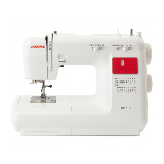
Summary of Contents for Janome HD718
-
Page 1: Parts List
First Edition: 19 May 2017 SERVICE MANUAL & PARTS LIST MODEL: HD718... -
Page 2: Table Of Contents
CONTENTS WHAT TO DO WHEN .................... SERVICE ACCESS FACE COVER ..................TOP COVER ..................BASE PLATE ..................BED COVER ..................BELT COVER ..................FREE ARM COVER ................FRONT COVER ..................REAR PANEL ..................MECHANICAL ADJUSTMENT TOP TENSION ..................PRESSER BAR HEIGHT AND ALIGNMENT ........NEEDLE SWING .................. -
Page 3: What To Do When
WHAT TO DO WHEN CONDITION CAUSE HOW TO FIX REFERENCE 1. Skipping 1. Needle is not inserted Insert the needle properly. stitches properly. 2. Needle is bent or worn. Change the needle. 3. Incorrectly threaded. Rethread. 4. Needle or thread are Use the recommended inappropriate for sewing needle and thread. - Page 4 CONDITION CAUSE HOW TO FIX REFERENCE 3. Breaking 1. Initial sewing speed is Start with medium speed. upper too fast. thread 2. Thread path is incorrect. Use the proper thread path. 3. Needle is bent or worn. Replace with a new needle. 4.
- Page 5 CONDITION CAUSE HOW TO FIX REFERENCE 6. Noisy 1. Backlash between See mechanical P.20 operation Shuttle hook gear and adjustment “Backlash lower shaft gear is too (lower shaft gear).” great. 2. Lower shaft gear is Eliminate the looseness. loose. 3. Inappropriate belt See mechanical P.27 tension.
-
Page 6: Service Access
SERVICE ACCESS FACE COVER Open the face cover (A). Remove the setscrews (B). Take the face cover (A) off. TOP COVER Open the face cover (A). Remove setscrews (B) and (C). Take the top cover (D) off. * When you replace the top cover, set the projection (E) into the groove (F) of the belt cover. -
Page 7: Base Plate
SERVICE ACCESS BASE PLATE Remove 4 setscrews (A). Remove the base plate (B). BED COVER Remove 2 setscrews (D). Remove the bed cover (E). * When you replace the bed cover, set the drop lever (F) in the left position as illustrated. -
Page 8: Belt Cover
SERVICE ACCESS BELT COVER Belt cover Projection Latch Loosen setscrew (A) and remove setscrew (B). Pull the right side of belt cover in the direction of arrow, to and take the latch off. Then remove the belt cover. When you attach the belt cover, set the projection into the groove of the front cover. FREE ARM COVER Needle plate Free arm cover... -
Page 9: Front Cover
SERVICE ACCESS FRONT COVER Open the face cover . Remove the top cover (See page 4), and the belt cover. (See page 6) Remove setscrew (A), (B). Loosen setscrews (C), (D) then remove the front cover (E). Pull the front cover off the latch (F) of the rear cover. Remove the lower part of the thread guide (G). -
Page 10: Rear Panel
SERVICE ACCESS REAR PANEL Twist and remove the arm cover Presser foot lever part from the presser foot lever. Rear panel unit Open the face cover. Remove the top cover unit (See page 4), The belt cover (See page 6) and the front cover. (See page 7) Remove setscrews (A) ,(B), (C), and loosen setscrews (D) - (F). -
Page 11: Mechanical Adjustment
MECHANICAL ADJUSTMENT TOP TENSION TO CHECK: Set the tension dial at “4” and raise the presser foot. Pass the thread (A) between the discs and draw the thread (A) down around the check spring holder as in fig. 1. Lower the presser foot and bring the thread (A) up. Top tension should be 75 - 90g when pulling the thread (A) up in the direction of (B). -
Page 12: Presser Bar Height And Alignment
MECHANICAL ADJUSTMENT PRESSER BAR HEIGHT AND ALIGNMENT TO CHECK: Raise the presser foot lever (B). The distance between the zigzag foot (A) and the needle plate (C) should be 6.0 mm. If not, adjust as follows. ADJUSTMENT PROCEDURE: Open the face cover. Raise the presser foot lever (B) and loosen the hexagonal socket screw (D) on the presser bar holder (E). -
Page 13: Needle Swing
MECHANICAL ADJUSTMENT NEEDLE SWING TO CHECK: If the needle bar starts sideways while the needle is in the fabric at sewing the zigzag pattern, adjust the needle swing: (The needle should start swinging when 2 to 3mm above the needle plate.) ADJUSTMENT PROCEDURE: Remove the top cover (See page 4), set the pattern selector dial at "... -
Page 14: Straight Stitching
MECHANICAL ADJUSTMENT STRAIGHT STITCHING TO CHECK: Set the stitch width dial at " 0 " and the stitch selector at" " . Turn the handwheel toward you. The needle should not swing side to side at this setting. ADJUSTMENT PROCEDURE: Remove the top cover. -
Page 15: Distribution Of Needle Swing
MECHANICAL ADJUSTMENT DISTRIBUTION OF NEEDLE SWING TO CHECK: Set the stitch width dial to " 0 " and the stitch selector at " ". Raise the needle to its highest position. Place the darning plate on the needle plate. Place a piece of paper on the darning plate and lower the presser foot. Lower the needle to mark needle point (A) on a piece of paper by turning handwheel. -
Page 16: Stretch Stitch Balance
MECHANICAL ADJUSTMENT STRETCH STITCH BALANCE TO CHECK: Set the stitch selector at . Set the stitch length dial at S.S. position, and stretch stitch adjuster at " ". Place a piece of paper on the needle plate and lower the presser foot. Turn the handwheel to mark needle points on the paper. - Page 17 MECHANICAL ADJUSTMENT STRETCH STITCH BALANCE ADJUSTMENT PROCEDURE: Remove the cap (F). If the reverse stitch length (B) is shorter than the forward stitch length (A), turn the adjusting setscrew (E) in the direction of (C). If the reverse stitch length (B) is longer than the forward stitch length (A), turn the adjusting setscrew (E) in the direction of (D).
-
Page 18: Feed Dog Height
MECHANICAL ADJUSTMENT FEED DOG HEIGHT The highest position of the feed dog should be between 0.8 to 0.9 mm from the surface of the needle plate when the pressure dial is set at "3" and the presser foot is raised. 1. -
Page 19: Clearance Between Needle And Hook
MECHANICAL ADJUSTMENT CLEARANCE BETWEEN NEEDLE AND HOOK The clearance between the test pin and the tip of the hook should be between –0.10 and +0.05 mm. PREPARATION: Turn on the power switch and set the stitch pattern to maximum zigzag width " ". -
Page 20: Needle To Hook Timing
MECHANICAL ADJUSTMENT NEEDLE TO HOOK TIMING The hook timing is that amount of ascending travel of the needle bar from its lowest position to where the tip of the rotary hook meets the left side of the needle should be 3.25 to 3.55 mm. -
Page 21: Needle Bar Height
MECHANICAL ADJUSTMENT NEEDLE BAR HEIGHT The distance between the upper edge of needle eye and the tip of the hook should be in the range of 1.6-2.0 mm when the tip of hook meets the right side of the needle in ascending travel of needle from its left and lowest position. -
Page 22: Backlash (Lower Shaft Gear)
MECHANICAL ADJUSTMENT BACKLASH ( LOWER SHAFT GEAR ) TO CHECK: Remove the needle plate and bobbin holder. Turn the hand wheel slowly toward you until the tip of the shuttle hook (A) is between both ends (b) of the feed dog. Rotate the hook race clockwise and counter clockwise by hand and check the play. -
Page 23: Buttonhole Stitch Balance
MECHANICAL ADJUSTMENT BUTTONHOLE STITCH BALANCE TO CHECK: Set the machine as follows: STITCH SELECTOR ... STITCH LENGTH DIAL ..BLUE ZONE STITCH WIDTH DIAL ..6.5 Attach the automatic buttonhole foot. Sew buttonhole and check the stitch balance between the right side and left side of buttonhole. -
Page 24: Needle Position
MECHANICAL ADJUSTMENT NEEDLE POSITION TO CHECK: Set the machine as follows: STITCH SELECTOR ... STITCH WIDTH DIAL ..6.5 Turn the handwheel toward you until the needle comes to the center position. The needle should not move when you turn the stitch width dial at " 0 ". ADJUSTMENT PROCEDURE: Remove the top cover. -
Page 25: Zero Feeding
MECHANICAL ADJUSTMENT ZERO FEEDING TO CHECK: Set the stitch selector to and the stitch length dial to "0". Place a piece of paper on the needle plate. Check if the paper moves FORWARD OR BACKWARD when you turn the handwheel toward you. -
Page 26: Replacement And Adjustment Of The Needle Threader Plate
MECHANICAL ADJUSTMENT REPLACEMENT AND ADJUSTMENT OF THE NEEDLE THREADER PLATE If the hook of the threader plate is damaged, change or adjust the part as follows: TO CHANGE THE THREADER PLATE: TO REMOVE: Push down the needle threader knob and pull the needle threader plate (A) down to remove it (FIG 1). -
Page 27: Buttonhole Function (1)
MECHANICAL ADJUSTMENT BUTTONHOLE FUNCTION (1) * A buttonhole sewn with the automatic buttonhole foot will be 3 mm longer than the actual button. The length can be adjusted as follows: ADJUSTMENT PROCEDURE: Lower the feed dog and attach foot R, Then lower the presser bar. Loosen the setscrew (A). -
Page 28: Buttonhole Function (2)
MECHANICAL ADJUSTMENT BUTTONHOLE FUNCTION (2) *If the bartack on the buttonhole occurs too early, or if no bartack is sewn at all, adjust as follows. 1. Remove the belt cover (See page 23). 2. Loosen the setscrew. 3. Make adjustment so the plate (2) touches the arm lightly with plate (1) pushed in the direction of arrow. -
Page 29: Motor Belt Tension
MECHANICAL ADJUSTMENT MOTOR BELT TENSION TO CHECK: The correct motor belt tension is achieved when the belt pushes in about 7 mm - 9 mm under a pressure of about 300 grams. ADJUSTMENT PROCEDURE: Remove the belt cover. (See page 6) Loosen setscrews (A) and (B). -
Page 30: Replacing Transfomer
REPLACING TRANSFORMER TO REMOVE: Remove the base. (See page 5) Remove the machine socket and the connector. Remove the connector from the lamp. Remove the setscrew (A) (3pcs.) to remove the cover. Remove the setscrew (C) (2pcs.) to remove the transformer. TO ATTACH: Follow the procedure above in reverse. -
Page 31: Wiring Of Terminal Block
WIRING OF TERMINAL BLOCK Remove the rear cover. (See page 8.) Remove the screws (A), (B) and machine socket cover. Follow the above procedure in reverse. Machine socket cover Machine socket unit Trancefomer Motor... -
Page 32: Oiling
OILING Factory lubricated parts will provide years of household sewing without routine oiling. However, whenever the machine is being serviced, check to see if any parts needs to be lubricated. OIL: Use good quality sewing machine oil at the points (A, B, C, D, E, F & G) indicated by the black arrows. -
Page 33: Parts List
PARTS LIST... - Page 34 MODEL: HD718 PARTS LIST...
- Page 35 MODEL: HD718 PARTS LIST PARTS DESCRIPTION 755602009 Top cover (unit) 755003004 Top cover 653022000 Thread guide 751092008 Pre-tension spring 820374004 Setscrew 2x2.3 000107905 Setscrew 3x6 (B) 730501011 Thread guide plate (unit) 000160102 Adjustable rock nut 4 735016307 Bobbin winder stopper...
- Page 36 MODEL: HD718 PARTS LIST...
- Page 37 MODEL: HD718 PARTS LIST PARTS DESCRIPTION 755635506 Front cover (unit) 755029A02 Front cover 753125007 Thread guide 755073005 Stitch length adjusting dial 755058004 Zigzag width adjusting slider 000163105 Setscrew 2.3x5 (B) 755059005 Cover plate 000120203 Setscrew 3x8 (B) 755046009 Indicator window frame...
- Page 38 MODEL: HD718 PARTS LIST...
- Page 39 MODEL: HD718 PARTS LIST PARTS DESCRIPTION 755603170 Face cover (unit) 755005604 Face cover 650025004 Face cover spring 000161206 Setscrew 3x10 (B) 840602006 Thread cutter (unit) 366501102 Face cover hinge (unit) 000081119 Setscrew 4x6 751345009 Presser bar base plate 000081005 Setscrew 4x8...
- Page 40 MODEL: HD718 PARTS LIST...
- Page 41 MODEL: HD718 PARTS LIST PARTS DESCRIPTION 755627000 Needle bar supporter (unit) 751014006 Needle bar supporter 000111201 Hexagonal socket screw 4x4 751630004 Needle bar (unit) 807607019 Threader positioning set plate (unit) 807018109 Threader positioning set plate 000111902 Hexagonal socket screw 3x4...
- Page 42 MODEL: HD718 PARTS LIST...
- Page 43 MODEL: HD718 PARTS LIST PARTS DESCRIPTION 755634000 Front base plate (unit) 505061009 Front base plate 751022007 Pulling bar link 000002105 Snap ring E-3 751657007 BH lever (unit) 751610008 BH lever 753026203 BH lever supporter plate 753027008 Friction spring 652203004 Setscrew 3x3.5 000023009 Spring pin 1.6x4...
- Page 44 MODEL: HD718 PARTS LIST...
- Page 45 MODEL: HD718 PARTS LIST PARTS DESCRIPTION 756607007 Upper shaft (unit) 756504003 Upper shaft 757072000 Worm 000111201 Hexagonal socket screw 4x4 731384008 Felt 000111304 Hexagonal socket screw 5x5 650071005 Timing belt 673062004 Upper shaft rear bushing 756017004 Upper shaft gear 000020501...
- Page 46 MODEL: HD718 PARTS LIST...
- Page 47 MODEL: HD718 PARTS LIST PARTS DESCRIPTION 751640306 Feed rock shaft (unit) 840005003 Feed dog 000104005 Setscrew 3.5x8 650085002 Feed base spring 738055008 Straight pin 000111304 Hexagonal socket screw 5x5 650612004 Feed regulator (unit) 820387000 Ring 000081005 Setscrew 4x8 652050004 Feed regulator spring...
- Page 48 MODEL: HD718 PARTS LIST...
- Page 49 MODEL: HD718 PARTS LIST PARTS DESCRIPTION 756630308 Hook race (unit) 660536004 Hook body (unit) 508514001 Hook body gear (unit) 508137006 Hook body bottom plate 820374004 Setscrew 2x2.3 627190010 Magnet 508118001 Hook bottom plate 508139008 Setscrew 2x2.3 820123006 Hook race shaft...
- Page 50 MODEL: HD718 PARTS LIST...
- Page 51 MODEL: HD718 PARTS LIST PARTS DESCRIPTION 650156005 Zigzag width rod (front) 000002105 Snap ring E-3 686618001 Zigzag arm (unit) 000081005 Setscrew 4x8 751058002 Zigzag width rod 755057003 Zigzag width adjusting rod 751692004 Reverse lever (unit) 751269008 Reverse lever (1) 751055102...
- Page 52 MODEL: HD718 PARTS LIST...
- Page 53 MODEL: HD718 PARTS LIST PARTS DESCRIPTION 753619003 Idler (unit) 753119008 Idler base 625217100 Idler 000002806 Snap ring E-6 000081005 Setscrew 4x8 755060009 Belt cover 000115607 Setscrew TP 4x8 000080901 Setscrew 4x25 753678011 Machine socket (whole unit) 752671309 Motor (unit) M-2086A-1...
- Page 54 MODEL: HD718 PARTS LIST...
-
Page 55: Parts List
MODEL: HD718 PARTS LIST PARTS DESCRIPTION 755870103 Accessory set 102261103 Bobbin 647808009 Seam ripper (unit) 822019509 Small spool pin 625031500 Additional spool pin 653802002 Screwdriver key 647803004 Screwdriver 802424004 Lint brush 102403109 Spool pin felt 802422002 Quilter 822804118 Satin stitch foot...
Need help?
Do you have a question about the HD718 and is the answer not in the manual?
Questions and answers