Table of Contents
Advertisement
Quick Links
Advertisement
Table of Contents

Related Manuals for Sky-Drones SMARTAP PRO

Summary of Contents for Sky-Drones SMARTAP PRO
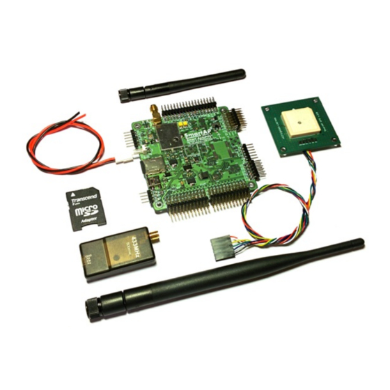
- Page 1 Flight Control System User’s Guide www.sky-drones.com All rights reserved...
-
Page 2: Table Of Contents
SmartAP PRO 1 SmartAP MAX Introduction Set includes Description Flight performance General Processor Sensors Flight Modes Interfaces Size and Weight SmartAP GNSS Specifications Features Package includes Dimensions SmartAP RTK Specifications Features Package includes Sky-Drones - SmartAP Flight Control Systems 2 / 89... - Page 3 SmartAP AutoPilot User’s Guide CONTENT SmartAP PDB Introduction Features SmartAP PRO Mounting the board Connections External GNSS / MAG SmartAP PRO 0.2 and later SmartAP PRO 0.1 and earlier GPS Receiver RC Receiver RSSI Monitoring Motors ESC Telemetry module OSD Video Electromagnetic sounder Power supply LED &...
- Page 4 F450 Quadcopter 3DR Hexacopter Updating GNSS Module Getting U-Center RTK GNSS Configuration update SmartAP PRO Onboard GNSS module update Modes overview Flight Modes overview Mode Switch: 3 position switch (Main mode control): Auto Switch: 2 position switch (Auto mode control):...
- Page 5 Flying with RTK GNSS Locating the antenna Connecting in SmartAP GCS Starting Survey-In Survey-In completed RTK Modes Geotag images Processing the Logs Support Safety Safety basics Additional safety information Support Disclaimer Revision history Sky-Drones - SmartAP Flight Control Systems 5 / 89...
-
Page 6: Introduction
Introduction Sky-Drones - the leading manufacturer of autopilots and flight control systems solutions which can be applied to a wide range of Drones (UAVs) applications such as Surveying, Mapping, Inspection, Security, Safety and High-Quality Media production. The company has an outstanding background and experience in Research and Development, Manufacturing and Delivering products and solutions for extremely rapidly growing market in Drones / UAV segment. -
Page 7: Smartap Gnss
As well as many other peripherals and electronics needed for autonomous unmanned aerial vehicles: SmartAP GNSS GPS/GLONASS receiver with integrated patch antenna, magnetometer and pressure sensor SmartAP RTK GPS/GLONASS RTK (Real-Time Kinematics) receiver for high-precision positioning Sky-Drones - SmartAP Flight Control Systems 7 / 89... -
Page 8: Smartap Pdb
SmartAP PDB Power Distribution Board for ESCs / Motors power supply and 5V / 12V generation Purchase the Hardware in official Sky-Drones Store Software SmartAP GCS (Ground Control Station) is the software application which allows you to plan and create autonomous missions for your SmartAP Autopilot as well as control the UAV using intuitive high-level commands. -
Page 9: Smartap Pro
SmartAP PRO Introduction SmartAP PRO Autopilot is the latest generation of professional flight control system for multirotor Unmanned Aerial Vehicles capable of fully autonomous flight. It has a powerful microcontroller, multiple redundant 9-axis Inertial Measurement Unit (Gyroscopes, Accelerometers, Magnetometer) with temperature stabilization, integrated telemetry module, external GNSS module with the latest with integrated magnetometer. -
Page 10: Description
Powerful microcontroller 32 bit 168 MHz STM32F4 ARM Cortex M4 Compact board size of 8x8 cm (3.15"x3.15"), weight 60g, 6 layers PCB design Power supply from the main LiPO battery (3S - 14S) support, up to 60 Volts Sky-Drones - SmartAP Flight Control Systems 10 / 89... -
Page 11: Sensors
Altitude Hold Position Hold Return to Home Autonomous Waypoints Flight Guided Follow me Take off Landing Size and Weight Length: 80mm Width: 80mm Height: 17mm Weight: 39g Previous versions SmartAP PRO 2 Sky-Drones - SmartAP Flight Control Systems 11 / 89... -
Page 12: Smartap Pro 1
SmartAP AutoPilot User’s Guide SmartAP PRO SmartAP PRO 1 Sky-Drones - SmartAP Flight Control Systems 12 / 89... -
Page 13: Smartap Max
And many more… General Powerful microcontroller 32 bit 168 MHz STM32F4 ARM Cortex M4 Compatible with GPS/GLONASS receiver (UBlox NEO8, GPS/GLONASS, up to 24 sats, 10 Hz) active antenna Integrate OSD (On-Screen Display) Sky-Drones - SmartAP Flight Control Systems 13 / 89... -
Page 14: Processor
1x LED Output port 3x UART 2x I2C 1x SPI 2x CAN 1x Camera input 1x Camera output 1x USB Mini-B Size and Weight Length: 63mm Width: 43mm Height: 16mm Weight: 21g Sky-Drones - SmartAP Flight Control Systems 14 / 89... -
Page 15: Smartap Gnss
Integrated magnetometer - HMC5883L Footprint for pressure sensor - MS5611-01BA03 UART port for GPS interface Diameter 75 mm Weight 18g Fully compatible with SmartAP Autopilots Package includes GNSS Module Connection cable Dimensions Sky-Drones - SmartAP Flight Control Systems 15 / 89... - Page 16 SmartAP AutoPilot User’s Guide SmartAP GNSS Sky-Drones - SmartAP Flight Control Systems 16 / 89...
-
Page 17: Smartap Rtk
Base station module length 3 m Fully compatible with SmartAP Autopilots Package includes Base station module Active patch antenna for base station module Airborne module with integrated patch antenna Connection cable Sky-Drones - SmartAP Flight Control Systems 17 / 89... -
Page 18: Smartap Pdb
Integrated loud electromagnetic sounder (buzzer) Power output for the flight controller (both 5V and battery VIN) Fully compatible with all SmartAP Autopilots For further information, please, refer to the Installation section. Sky-Drones - SmartAP Flight Control Systems 18 / 89... -
Page 19: Smartap Pro
External GNSS / MAG If you’re using external GNSS / Magnetometer module board then the connection should be as following: SmartAP PRO 0.2 and later GNSS / Magnetometer cable goes to dedicated GNSS / MAG port having 6 wires (... -
Page 20: Smartap Pro 0.1 And Earlier
SmartAP AutoPilot User’s Guide SmartAP PRO SmartAP PRO 0.1 and earlier GPS Cable (4 wires: ) goes to GPS port and magnetometer cable (I2C: ) goes to Magnetometer port as shown on the picture above. Make sure to place GPS module as far as possible from:... -
Page 21: Rssi Monitoring
RSSI information will appear in the GCS and also on OSD RSSI PWM I/0 #13 screen. Motors ESC Connect ESC inputs to SmartAP PWM outputs 1-12. The first motor is always front or front-right, it’s spinning direction is CCW. Sky-Drones - SmartAP Flight Control Systems 21 / 89... -
Page 22: Telemetry Module
Connect Electromagnetic sounder to BUZ port of SmartAP. Power supply Connect power supply cable from main power distribution board of the UAV: SmartAP PRO 0.1 and earlier: 10-36 V, 3S – 8S SmartAP PRO 0.2 and later: 10-60 V, 3S – 14S LED & Buzzer Buzzer: 12V, 0.2A (included in the kit) LED 1-4: 12V, 0.2A per each channel (enough to power LED strip of 25cm length) -
Page 23: Dimensions
Dimensions of the board are 80x80 mm. Mounting holes diameter is 3 mm, distance between the center of the mounting hole and board edges is 4.5 mm. SmartAP PRO v .2 pinout Sky-Drones - SmartAP Flight Control Systems 23 / 89... -
Page 24: Smartap Pro V .1 Pinout
SmartAP AutoPilot User’s Guide SmartAP PRO SmartAP PRO v .1 pinout Sky-Drones - SmartAP Flight Control Systems 24 / 89... -
Page 25: Smartap Pro V .0 Pinout
SmartAP AutoPilot User’s Guide SmartAP PRO SmartAP PRO v .0 pinout Sky-Drones - SmartAP Flight Control Systems 25 / 89... - Page 26 SmartAP AutoPilot User’s Guide SmartAP PRO Sky-Drones - SmartAP Flight Control Systems 26 / 89...
-
Page 27: Smartap Max
RF emitting devices, such as video transmitters High-current cables (ESC / motors power supply) It’s recommended to use GPS mast for that. Connect the cable and put the GPS on a mast. Connecting Peripherals Metal case version Sky-Drones - SmartAP Flight Control Systems 27 / 89... -
Page 28: Plastic Case Version
Make sure NOT to mix up polarity. GND line (black) is always near edge (bottom) RC Receiver Connect PPM / SBUS output of the RC receiver to PPM / SBUS Input port of SmartAP. Sky-Drones - SmartAP Flight Control Systems 28 / 89... -
Page 29: Esc / Motors Pwm
Connect the one side of the cable to GNSS module and the other one to the GPS / MAG port of the autopilot as shown on the pictures below: Telemetry Module Connect the one side of the cable to air telemetry module and the other one to the RADIO port of the autopilot as shown on the pictures below: Sky-Drones - SmartAP Flight Control Systems 29 / 89... -
Page 30: Power Module
Relay commutation - if you want to use relay, connect the pins which should be shorted / unshorted upon activation to relay pins RCOM (marked yellow): ROUT Sky-Drones - SmartAP Flight Control Systems 30 / 89... -
Page 31: Assembled System
In case you want to use camera feedback of the moment when the photo was actually taken (for Log file and precise geotagging later) then you need to connect pins marked above to the signal and ground of the interface which provides camera feedback. Assembled System Fully assembled and mounted system should look as follows: Sky-Drones - SmartAP Flight Control Systems 31 / 89... -
Page 32: Smartap Pdb
(e.g. 8-10 AWG) to be able to handle high current loads and even more using thinner wires. Both top and bottom, left and right sides have pads for ESCs power supply connection. Therefore, up to 12 ESCs can be connected. Sky-Drones - SmartAP Flight Control Systems 32 / 89... -
Page 33: Soldering
It's strongly recommended to use powerful solder iron (at least 80W), otherwise, there is a high chance of cold joint which can significantly reduce the reliability. Soldered Power Distribution Board should look as follows: Sky-Drones - SmartAP Flight Control Systems 33 / 89... -
Page 34: Powering The Autopilot
SmartAP PRO SmartAP PRO autopilot is capable of getting the power directly from the main battery, therefore, specially dedicated solder terminals can be used. If you would like the autopilot to get the current sensor (integrated in PDB) readings - simply connect the... -
Page 35: Smartap Max
SmartAP MAX gets the power supply and voltage / current readings from the PDB using standard 6-pin cable with Molex PicoBlade connectors. Simply connect the cable to connector of the autopilot. Sky-Drones - SmartAP Flight Control Systems 35 / 89... -
Page 36: Buzzer Support
Voltage and current sensors SmartAP PDB has integrated voltage and current sensors. Current sensor is located on the bottom side of the PDB. For correct scale / offset configuration, please, refer to Configuration section. Sky-Drones - SmartAP Flight Control Systems 36 / 89... -
Page 37: Drivers Installation
Open CMD as administrator SET DEVMGR_SHOW_NONPRESENT_DEVICES=1 Type to open Device manager devmgmt.msc Click > View Show hidden devices More information and description on the steps above can be found here Sky-Drones - SmartAP Flight Control Systems 37 / 89... - Page 38 . Go to the Download section of the website and get the driver .inf file for the autopilot. Browse my Computer for Driver Software Specify the location of the driver in menu. Browse Sky-Drones - SmartAP Flight Control Systems 38 / 89...
- Page 39 SmartAP AutoPilot User’s Guide Drivers installation When pop up window comes choose Install driver anyway The process might take a few seconds. Sky-Drones - SmartAP Flight Control Systems 39 / 89...
- Page 40 Unplug and plug in the USB cable of the autopilot to reboot the board and then if you go to you'll see that the driver is now Device Manager installed successfully: Sky-Drones - SmartAP Flight Control Systems 40 / 89...
- Page 41 SmartAP AutoPilot User’s Guide Drivers installation Sky-Drones - SmartAP Flight Control Systems 41 / 89...
-
Page 42: Getting The Software
Run the applications after installation and if you're able to see the authorization window then it means that the application was installed successfully and you may proceed to the next steps. Sky-Drones - SmartAP Flight Control Systems 42 / 89... -
Page 43: Create Account
World pane Once you fill in the details click . If you're registered successfully you'll get into the app and will see the main pane which is called SIGN UP World. Sky-Drones - SmartAP Flight Control Systems 43 / 89... -
Page 44: App Menu
Clicking the gear will open UAV settings menu. The main tab shows information concerning hardware, installed firmware and unique ID. Tabs at left provide the navigation between various settings of the flight controller which will be described in the further chapters. Sky-Drones - SmartAP Flight Control Systems 44 / 89... -
Page 45: Links Management
If you are about to configure a new Flight Controller unit it is recommended to use USB connection instead of wireless telemetry. First connection Select the desired connection, click and then CONNECT Sky-Drones - SmartAP Flight Control Systems 45 / 89... - Page 46 Therefore, if you see the message above, please, proceed to Firmware Upgrade procedure described in the next chapter. Sky-Drones - SmartAP Flight Control Systems 46 / 89...
-
Page 47: Firmware Update
WHAT'S NEW UPGRADE The firmware will be downloaded from Sky-Drones cloud platform. Sometimes after pressing the button you might see the reboot request. Simply plug out and then plug in flight controller USB cable. Sky-Drones - SmartAP Flight Control Systems... - Page 48 Once the procedure started you will see progress notification and status. Usually update procedure takes from 30 to 60 seconds. After upgrade procedure successfully finished you will see the confirmation message. Sky-Drones - SmartAP Flight Control Systems 48 / 89...
-
Page 49: Custom Firmware Upload
In case something is not going right during the firmware upgrade you might want to see the logs to further understand the issue or provide this information to our support team. Simply click Options icon (three dots) in the top-right corner and select Show Update Log Sky-Drones - SmartAP Flight Control Systems 49 / 89... - Page 50 SmartAP AutoPilot User’s Guide Firmware update Sky-Drones - SmartAP Flight Control Systems 50 / 89...
-
Page 51: General Configuration
Click and choose your airframe from the list. If you can’t see your airframe there – feel free to contact us and we’ll add the new AIRFRAME airframe type for you. Sky-Drones - SmartAP Flight Control Systems 51 / 89... -
Page 52: System Orientation
/ max values. You may apply reverse if needed. Motors IDLE speed If you want the motors slightly spinning when the system is Armed you can set Motors IDLE speed to the desired value. Sky-Drones - SmartAP Flight Control Systems 52 / 89... -
Page 53: Radio
When it’s done – press OK button to stop calibration and save parameters. You can remap any action to the desired channel and apply reverse if needed. Sky-Drones - SmartAP Flight Control Systems 53 / 89... -
Page 54: Sensors
Sensors configuration tab allows to perform accelerometer, gyroscope and magnetometer calibrations which are very important for excellent flight performance. Accelerometer calibration Click button near accelerometer data. Click and follow the instructions which will be shown after procedure started. CALIBRATE START Sky-Drones - SmartAP Flight Control Systems 54 / 89... -
Page 55: Gyroscope Calibration
CALIBRATE START after procedure started. Magnetometer Magnetometer calibration is highly important for precise position hold and autonomous flight modes. Make sure that you’re outdoors and don’t Sky-Drones - SmartAP Flight Control Systems 55 / 89... -
Page 56: Gnss Configuration
CONFIGURE CONFIGURE system reboot. Battery Set battery sensor type. The system supports several battery sensors: Generic power module SmartAP PDB SmartAP 3.x internal monitoring Sky-Drones - SmartAP Flight Control Systems 56 / 89... -
Page 57: Tuning
3. The most important parameters are Stabilization Rate Roll / Pitch. Increase it until you see high-frequency oscillations or decrease if you can already see them. Normally, this value is in between 0.1 – 0.2 depending on your airframe size, motors, ESC, props and vibration Sky-Drones - SmartAP Flight Control Systems 57 / 89... -
Page 58: Control
In OSD settings you can: Enable / disable OSD module Select Metric or Imperial type of the units depending on your preferences Narrow the overlay area to fit the information on the screen Sky-Drones - SmartAP Flight Control Systems 58 / 89... - Page 59 OSD support both PAL and NTSC video standards with auto detection and selection. Typical information layout is shown on the images below: PAL Layout NTSC Layout The actual layout on the screen typically looks as following: Sky-Drones - SmartAP Flight Control Systems 59 / 89...
-
Page 60: Camera
: Shutter configuration has settings for minimum and maximum output values for the triggering pulse. Interval is the time of how long the Shutter pulse should be in active state to initiate the shutter of the camera to trigger. Sky-Drones - SmartAP Flight Control Systems 60 / 89... -
Page 61: Parameters
SmartAP AutoPilot User’s Guide General configuration Parameters Parameters tab gives you direct access to all parameters available in the system. Sky-Drones - SmartAP Flight Control Systems 61 / 89... -
Page 62: Standard Pid Presets
This section includes default parameters examples for various configuration types. You can find the airframe which suits your mostly and have parametes value reference for tuning. MicroDrones MD4-1000 Quadcopter T960 Hexacopter Sky-Drones - SmartAP Flight Control Systems 62 / 89... -
Page 63: F450 Quadcopter
SmartAP AutoPilot User’s Guide Standard PID presets F450 Quadcopter Sky-Drones - SmartAP Flight Control Systems 63 / 89... -
Page 64: 3Dr Hexacopter
SmartAP AutoPilot User’s Guide Standard PID presets 3DR Hexacopter Sky-Drones - SmartAP Flight Control Systems 64 / 89... -
Page 65: Updating Gnss Module
Then go to U-Center utility and setup the connection in the top-left corner: choose the right COM port and set the baud rate to 115200. Then go to > and select the Configuration file (it’s available for download from the website). Set Tools GNSS Configuration Store configuration checked. into BBR / Flash Sky-Drones - SmartAP Flight Control Systems 65 / 89... -
Page 66: Smartap Pro Onboard Gnss Module Update
If the messages dialog closes itself in about a few seconds and you can’t see any error messages or reports then it means that the configuration of the GPS receiver has been successfully updated. SmartAP PRO Onboard GNSS module update Connect your FTDI cable to the GPS port of the flight controller as following: <->... - Page 67 Troubleshooting: If it seems that there is no connection to GPS module – try to change the TX and RX pins of FTDI cable connected to flight controller, sometimes colors meanings swapped Do not forget to put the switch back to RUN position Sky-Drones - SmartAP Flight Control Systems 67 / 89...
-
Page 68: Modes Overview
1. Disarm the system after landing by turning let stick left-down for a 1 second 2. Two short beeps mean that the system has been successfully disarmed 3. Power off the copter 4. Power off the transmitter Sky-Drones - SmartAP Flight Control Systems 68 / 89... -
Page 69: Transmitter Commands
Short beep means that the system goes into calibration mode. Short positive tone means that the calibration was done and you need to rotate the vehicle for the next calibration position. Once all six positions are calibrated you’ll hear the tone meaning that the calibration completed successfully and saved to SD card. Sky-Drones - SmartAP Flight Control Systems 69 / 89... -
Page 70: Gyroscope Calibration
Hold for 3 seconds and release Magnetometer calibration process starts after a beep. Short positive tone after 30 seconds means that the calibration was done successfully and saved to SD card. Sky-Drones - SmartAP Flight Control Systems 70 / 89... -
Page 71: Flying With Smartap Gcs
SmartAP GCS allows to see the real-time video feed right in the application. Click on the Gear icon in the bottom-left corner and select the video source you would like to use. You can change resolution and apply image rotation if needed. Sky-Drones - SmartAP Flight Control Systems 71 / 89... -
Page 72: Autonomous Flights
Waypoints flight Autonomous mission flights are based on waypoints navigation. To create a new mission or choose from the already existing ones simply click button and then click button. PLANNING MISSIONS Sky-Drones - SmartAP Flight Control Systems 72 / 89... - Page 73 We want to demonstrate creating new mission so we click now. CREATE Now you can see mission settings menu and Home point icon placed in the center of the map automatically. You can drag home point wherever you want. Sky-Drones - SmartAP Flight Control Systems 73 / 89...
- Page 74 : Heading angle in degrees to hold when flying to the next waypoint Heading When no waypoints selected - those settings are related to default values for new waypoints. New waypoints can be added by double-clicking on the map: Sky-Drones - SmartAP Flight Control Systems 74 / 89...
- Page 75 In the second case the vehicle should be on the ground before activating autonomous mode. After AUTO mode was activated the vehicle will start autonomous take off and then continue flying to the next waypoint. If the vehicle is airborne before starting AUTO it will skip the Take off waypoint. Sky-Drones - SmartAP Flight Control Systems 75 / 89...
- Page 76 Before the flight you need to ARM the system. The system can be armed using the RC transmitter stick or by clicking the ARM / DISARM button in the GCS. `ARM` command should be confirmed to make sure it wasn't clicked accidentally. Sky-Drones - SmartAP Flight Control Systems 76 / 89...
- Page 77 After the TAKE OFF vehicle is airborne you can press FLY button or switch to AUTO mode using your RC transmitter. The vehicle will start flying to the first waypoint. Sky-Drones - SmartAP Flight Control Systems 77 / 89...
-
Page 78: Guided Flight
GUIDED Once you clicked on the map the vehicle will start flying to that point and you will see the cross on the map indicating the target position of the vehicle. Sky-Drones - SmartAP Flight Control Systems 78 / 89... - Page 79 If you want to change the position of the vehicle you can simply drag&drop the cross on the map or right-click on the map and click Fly Here. Repositioning can be done anytime. Once the vehicle achieved the target position it starts hoveing at the point awaiting for the other point or flight mode change. Sky-Drones - SmartAP Flight Control Systems 79 / 89...
-
Page 80: Flying With Rtk Gnss
First of all open SmartAP GCS and connect to the drone. Then go to RTK tab in bottom part of the Main Window. Choose the COM port of GNSS module and press button. Once you're connected you'll see the status of the base station module. Connect Sky-Drones - SmartAP Flight Control Systems 80 / 89... -
Page 81: Starting Survey-In
Mean 3D STD accuracy after Survey-In process started Survey-In completed After Survey-In process is completed SmartAP GCS will start sending corrections to the Rover. Survey-In status will change from In Progress Completed Sky-Drones - SmartAP Flight Control Systems 81 / 89... -
Page 82: Rtk Modes
The drone will continue flying, probably with slightly lower accuracy, however, if the connection will not be regained in 60 seconds GNSS module will go into regular mode. Once the connection is established back the system will be back in RTK mode. Sky-Drones - SmartAP Flight Control Systems 82 / 89... -
Page 83: Geotag Images
To geotag images firstly download the log file. Then open SmartAP GCS, pull out the left drawer: And go to tab: Plot Click menu in top-right corner and click Options Open log file... Sky-Drones - SmartAP Flight Control Systems 83 / 89... - Page 84 CAM_TRIGGER And select the checkboxes for the fields you would like to export. Normally, all fields are recommended for further processing. Once selected - click and click Options Export CSV Sky-Drones - SmartAP Flight Control Systems 84 / 89...
- Page 85 Then you need to select the Folder destination where you want the log file to be exported to. After that you can open the file with any file editor and check its content: Later, this information can be used for further post processing and maps stitching. Sky-Drones - SmartAP Flight Control Systems 85 / 89...
-
Page 86: Processing The Logs
You'll see the folder will all log messages splitted in separate files For instance, if you're interested in GNSS (GPS/GLONASS) data you would need GNSS_REPORT.csv file. Sky-Drones - SmartAP Flight Control Systems 86 / 89... -
Page 87: Support
DISCOVERABLE. SOME JURISDICTIONS DO NOT ALLOW THE EXCLUSION OF IMPLIED WARRANTIES, SO SUCH EXCLUSION MAY NOT APPLY TO YOU.EXCEPT TO THE EXTENT REQUIRED BY APPLICABLE LAW, IN NO EVENT WILL SKY-DRONES BE LIABLE TO YOU ON ANY LEGAL THEORY FOR ANY SPECIAL, INCIDENTAL, CONSEQUENTIAL, PUNITIVE OR EXEMPLARY DAMAGES ARISING OUT OF THE USE OF THE HARDWARE. - Page 88 SmartAP AutoPilot User’s Guide Support Sky-Drones - SmartAP Flight Control Systems 88 / 89...
-
Page 89: Revision History
01.10.2015 - External GPS / Magnetometer connections 1.0.2 03.08.2015 - Added pinout description, PID tuning hints 1.0.1 09.12.2014 - Minor fixes in all sections 1.0.0 06.12.2014 - Initial release of the Guide Sky-Drones - SmartAP Flight Control Systems 89 / 89...
Need help?
Do you have a question about the SMARTAP PRO and is the answer not in the manual?
Questions and answers