Table of Contents
Advertisement
SERVICE
For mechanical disassembly and adjustment, refer to the "Mechanical Manual"
(DX7-R/RC, DX8-R/RC
VIDEO CASSETTE RECORDER
© Samsung Electronics Co., Ltd. OCT. 1997
VIDEO CASSETTE RECORDER
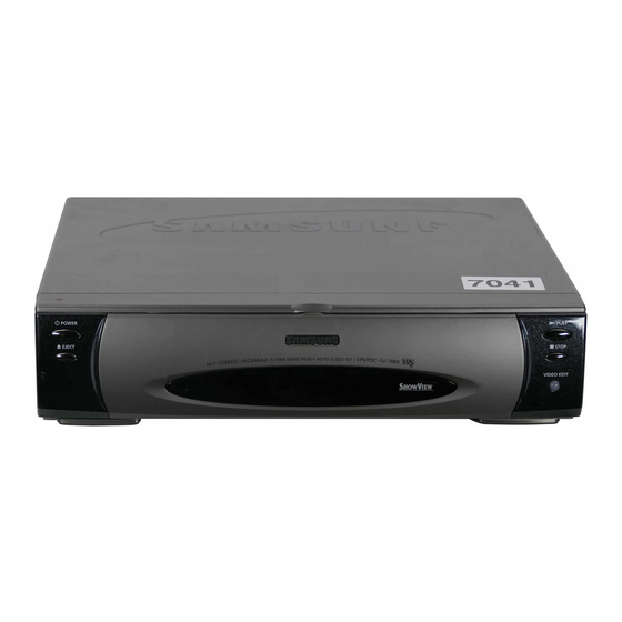
SV-A160X/SV-700X
AC68-20316A).
Manual
CONTENTS
PAL
AC68-20379A
Advertisement
Chapters
Table of Contents

Related Manuals for Samsung SV-A160X


Summary of Contents for Samsung SV-A160X
-
Page 1: Table Of Contents
Comparison Chart 4. Disassembly and Reassembly 5. Alignment and Adjustment 6. Exploded View and Parts List 7. Electrical Parts List 8. Block Diagrams 9. PCB Diagrams 10. Wiring Diagram 11. Schematic Diagrams © Samsung Electronics Co., Ltd. OCT. 1997 AC68-20379A... -
Page 2: Precautions
Alternatively, wear a discharging Wrist-strap device. (Be sure to remove it prior to applying power--this is an electric shock precaution.) Samsung Electronics... - Page 3 Always inspect for pinched, out- of-place, or frayed wiring. Do not change the spacing between components and the printed circuit board. Check the AC power cord for damage. Make sure that leads and components do not touch thermally hot parts. Samsung Electronics...
-
Page 4: Reference Information
2) If tape control signal is not connected to the jig, the VCR must be operated in SP mode. 2-1-2 Servicing Jig Jig Item Part No. Connects the deck ass’y to the main PCB connecting cable. X-5 Chassis Jig 68140-500-013 Samsung Electronics... - Page 5 6. Apply power to the function PCB. touching the start and end sensor LEDs. If the tape still does not load, reset the function PCB by 7. Insert a test tape into the housing ass’y. pressing SW715. Samsung Electronics...
- Page 6 CONNECTS TO THE ASS'Y MAIN CN601. CONNECTS TO THE CAPSTAN MOTOR CONNECTOR OF ASS'Y FULL DECK. CONNECTS TO THE LOADING MOTOR CONNECTOR OF ASS'Y FULL DECK. ASS'Y FULL DECK ASS'Y MAIN CN604 CN605 CN603 CN601 1 SCREW (1-3X10) 2 SCREWS (2-3X10) Samsung Electronics...
- Page 7 Reference Information MEMO Samsung Electronics...
-
Page 8: Product Specifications And Comparison Chart
68 dB min (IHF A filter) Frequency response 20Hz-20KHz Power requirement 230V (AC 50/60 Hz) Power consumption Approx. 21 watts Operation temperature 41°F-104°F (5°C-40°C) Operation humidity 10%-75% Weight 4.4 Kg (net) Dimensions (W x H x D) 380 x 90.5 x 310 mm Samsung Electronics... - Page 9 Product Specifications 3-2 Comparison Chart Samsung Electronics...
-
Page 10: Disassembly And Reassembly
4. Disassembly and Reassembly 4-1 Cabinet Assembly Note : Disassemble in the order shown. Reassemble in reverse order. 4-1-1 Cabinet Top removal Œ REMOVE 3 SCREWS. (BH:3-4X16-BLACK) Fig. 4-1 Cabinet Top removal Samsung Electronics... - Page 11 Disassembly and Reassembly 4-1-2 Bottom cover removal Œ REMOVE 2 SCREWS. (BH:2-3X12-YELLOW) "A" ´ LIFT UP THE BOTTOM COVER IN THE DIRECTION OF ARROW "A". Fig. 4-2 Bottom Cover removal Samsung Electronics...
- Page 12 Disassembly and Reassembly 4-1-3 Ass’y Front Panel removal Œ RELEASE 4 HOOKS. (Top view) ´ RELEASE 3 HOOKS. (Bottom view) Fig. 4-3 Ass’y Front Panel removal Samsung Electronics...
- Page 13 Disassembly and Reassembly 4-1-4 Ass’y Function-Timer removal Note : Take extreme care not to damage the PCB when removing it. ´ REMOVE THE FUNCTION-TIMER PCB IN THE DIRECTION OF ARROW. Œ RELEASE 5 TABS. Fig. 4-4 Ass’y Function-Timer removal Samsung Electronics...
- Page 14 CONNECTOR BOARD-ASS'Y ” LIFT THE ASS'Y MAIN UP TO REMOVE. Ø RELEASE 1 TAB "A" ∏ RELEASE 2 TABS. ˆ REMOVE 1 SCREW. (BH;3X12-YELLOW) Œ REMOVE THE CONNECTOR-WAFER IN THE DIRECTION OF ARROW "A". Fig. 4-5 Chassis Removal Samsung Electronics...
- Page 15 Disassembly and Reassembly 4-2 Circuit Board Locations Fig. 4-6 Circuit Board Locations Samsung Electronics...
-
Page 16: Alignment And Adjustment
PLAY PLAY STOP STOP MENU MENU Q-PRO Q-PRO SOFTEN SHARPEN TV/VCR SOFTEN SHARPEN TV/VCR SLOW A.DUB SLOW A.DUB PICTURE PICTURE AUDIO ADD BUTTON(AUDIO) TEST BUTTON IS HIDDEN BEHIND OF INLAY. Fig. 5-2 Remote Control Ass’y for X-7/X-8 Chassis Samsung Electronics... -
Page 17: Alignment And Adjustment
5-2-1 The number and position of test point Test point : TP02 (CTL Pulse) TP03 (H’D S/W -Trigger) TP04 (V. Envelope) TP05 (Audio out) AUDIO OUT H’D S/W -TRIGGER CTL PULSE V. ENVELOPE Fig. 5-3 The position of test point (Main PCB-Component side) Samsung Electronics... - Page 18 2) Set the tracking preset using the “FINE (Tracking, Fig. 5-4 Tracking preset adjustment TRK) button of remote control. REMOTE 3) After adjustment is completed, press the CONTROL PULSE REMOVE BUTTONS “POWER” button to release. PUSH TRACKING TRACKING PUSH Fig. 5-5 Tracking preset adjustment Samsung Electronics...
- Page 19 1) Simultaneously press the “TEST” button and “5” button in PB mode. This will adjust the tracking center automatically. 2) Set the tracking preset using the “FINE (Tracking, TRK) button of remote control. 3) After adjustment is completed, press the “POWER” button to release. Samsung Electronics...
-
Page 20: Electrical Adjustment
1) Insert an SP tape into the housing ass’y. 2) Press the “PLAY” button. 3) Press the “INPUT” button and “3” button simultaneously. 4) This will adjust the head S/W point adjustment automatically. 5) After the adjustment is completed, press “POWER” button to release. Samsung Electronics... - Page 21 Eject Cassette IN Cassette IN Unload Unload R. PS R. PS, Z-R. PS R. Slow Pinch Roller off Position Still Still, Slow, F-ADV Play PB, T-Stop, REC, Pause, F. PS, Z-FPS Stop Stop, Power off FF/REW FF, REW Samsung Electronics...
-
Page 22: Exploded View And Parts List
Housing Assembly - - - - - - - - - - - - - - - - - - - - - - - - - - - - - - - - - Remote Control Ass’y - - - - - - - - - - - - - - - - - - - - - - - - - - - - - - 6-10 Samsung Electronics... -
Page 23: Cabinet Assembly
Exploded View and Parts List 6-1 Cabinet Assembly Samsung Electronics... - Page 24 Exploded View and Parts List Loc. No Part No Description and Specification Remark DO NOT ORDER ASSY-FULL DECK;(DX8-R) (S.N.A) AC98-11224S ASSY-PANEL FRONT;SV-A160X,HIPS94HB AC98-11225L ASSY-FRONT DOOR;SV-A160X/SEG,IS PAL HI-F AC64-50838F DOOR-CASSETTE;SV-A160X,ABS94,HB,T2.5,L19 AC61-62003A SPRING;-,SUS304,(GE/RCA),-,-,-,- 62664-0021-00 DAMPER(ASSY);SV-70D AC61-10972V CONNECTOR BOARD-ASSY;SV-A160X/SEG,HIPS94 AC60-12126A SCREW-BH;-,BH,-,4*12,FE,FZY,-,-,- AC60-12134A SCREW-TAP BH;-,BH,-,2-4X16,-,FE AC60-10069A SCREW-TAPTITE;PH,+,-,M3,L10,ZPC3,SWRCH18...
-
Page 25: Mechanical Parts (Top Side)
Exploded View and Parts List 6-2 Mechanical Parts (Top Side) Samsung Electronics... - Page 26 UNIT-PINCH ROLLER;X-5,-,YAMAUCHI T236 AC66-10010A IDLER-ASSY;PACKAGE,-,X-5,- T237 AC61-40054A STOPPER-TAPE;POM M90-44,OD7,T1.5,NTR,X-5,- (OPTIONAL) T238 AC61-60132A SPRING ARM PINCH;CS,SUS304WPB,PI0.4,D7.1,OD7.9, T239 AC66-30132A LEVER JOG-ASSY;-,-,-,-.X5,- (DX8-R/RC ONLY) T240 AC61-60505A SPRING-REC S/W;-,ES,SUS304 WPB,PI0.29,PI3.5,- T300 AC96-10475Y ASSY-CYLINDER;-,CX5-H7P/DLC T302 AC31-12001M MOTOR-CYLINDER;E20XL03,-,- T303 AC33-12004S HEAD-BRUSH(ASSY);SECC20/20+CARBON,-,-,-,- T309 AC73-12001A RETRINER-RUBBER(ASSY);SECC+SILICON,-,-,- Samsung Electronics...
-
Page 27: Mechanical Parts (Bottom Side)
Exploded View and Parts List 6-3 Mechanical Parts (Bottom Side) Samsung Electronics... - Page 28 GEAR- WORM WHEEL;POM SW-01,M0.55/M1,Z57/Z10,GEA B261 AC66-30011A LEVER- SHIFT;PBT2002K,T10.9,L35,-,-,- B262 AC66-30012A LEVER- IDELR CHANGE;PBT330,T3.3,L50,-,W6.0,- B263 AC61-60111A SPRING-LEVER SHIFT;TS,SWPB,PI0.7,D5.5,L13.8(OD6.9 B264 AC59-90001A UNIT-LOADING ASSY;X-5,-,- B265 66823-0060-00 MOTOR-LOADING ASSY;POM+RF370C X-5 B266 AC66-20039A GEAR- WORM LO;PBT 2002K,-,-,-,D4.5,3,- B267 AC61-20224A HOLDER SHAFT;POM M90-44,T1.25,NAT,PI5XH5.5, B268 AC66-30149A BRAKE CAPSTAN-ASSY;POM,-,-,-,X5,- Samsung Electronics...
-
Page 29: Housing Assembly
Exploded View and Parts List 6-4 Housing Assembly H510 H520 H521 H533 H522 H530 H526 H532 H524 H531 H535 H540 H545 H544 H541 H550 H542 H543 H500 Samsung Electronics... - Page 30 LEVER- DOOR;LUCELN109-LD,T5,L74.3,W21.1,-, H540 62203-0104-00 CHASSIS-SIDE R(ASSY);ABS X5FL0505A X-5 H541 AC61-10003A CHASSIS- SIDE R;ABS HF-380,-,T10,BLK,-,X5,BLK H542 AC66-80008A SLIDER DAMPER;LUCEL N109-LD,T4,L87,-,-,- H543 AC61-60120A SPRING-SLIDE DAMPER;ES,SUS 304WPB,PI0.4,D3.8,L25(O H544 AC66-30016A LEVER- LID OPENER;LUCEL N109-LD,T5.0,L34.7,W16.6 H545 AC61-60123A SPRING-LID OPENER;TS,SWPB,PI0.55,D8.9,L15(OD10), H550 61403-0073-00 SHAFT-ARM(ASSY);SUM24L X5FL0405A X-5 Samsung Electronics...
-
Page 31: Remote Control Ass'y
Exploded View and Parts List 6-5 Remote Control Ass’y Loc. No Part No Description and Specification Remark AC59-10340G REMOCON-ASSY;-,NR-4250,-,-,SV-A160X,S/S AC64-50131A DOOR-BATTERY REMOCON;ABS94,HB,T1.5,D/GRY 2401-000795 C-AL;220UF,20%,16V,GP,-,8X11.5,3.5M 2203-000199 C-CERAMIC,CHIP;100NF,+80-20%,50V,Z5U,TP, 0407-000152 DIODE-ARRAY;MA159,80V,100MA,CX2,SOT-143, ICT1 AC09-10453K IC-MCU;Z86L7608,A160,28P,QFP,A120U,8B JST1 AC21-12001B JOG-SHUTTLE DAIL;-,-,-,-,-,SRGPPJ-013A LDT1 A4150-0168 LED-INFRARED;SI5312-H NTR 940NM/1.4V 0501-000592 TR-SMALL SIGNAL;2SD1781K-QR,NPN,200MW,SO... -
Page 32: Electrical Parts List
F1S01 A3065-0157 FUSE;FST 250V 1.6A 20MM SEMKO S505 C C321 2203-002188 C-CERAMIC,CHIP;10NF,+80-20%,16V,Y5V,TP,2 IC1P01 AC14-12001E IC;KA7809,-,- C322 2203-002188 C-CERAMIC,CHIP;10NF,+80-20%,16V,Y5V,TP,2 IC1S1 1203-001049 IC-PWM CONTROLLER;1L0380,TO-220F,4P,10MI C324 B1102-0113 C-FILM;CQ 922 P 100V 473-J CQ298PVT473J IC1S2 B4161-0030 PHOTO-COUPLER;PS2561-1 ST DIP C325 2202-000797 C-CERAMIC,MLC-AXIAL;10NF,30%,16V,Y5P,TP, Samsung Electronics... - Page 33 2007-001513 R-CHIP,MELF;4.7KOHM,5%,1/8W,DB,BK,2012 C3A10 2401-001904 C-AL;10UF,20%,16V,-,TP,4X7MM,5 R315 2007-001546 R-CHIP,MELF;3.9KOHM,5%,1/8W,DB,BK,2012 C3A11 2401-000918 C-AL;22UF,20%,16V,GP,-,6.3X7,5 R316 2007-001482 R-CHIP,MELF;6.8KOHM,5%,1/8W,DB,BK,2012 C3A12 2301-000383 C-FILM,PEF;10NF,5%,50V,TP,6X7X3.2MM,5MM R317 2007-001534 R-CHIP,MELF;33KOHM,5%,1/8W,DB,BK,2012 C3A13 2301-000402 C-FILM,PEF;1NF,5%,50V,TP,5X7X2.8MM,5MM R318 2007-001534 R-CHIP,MELF;33KOHM,5%,1/8W,DB,BK,2012 C3A15 2401-001917 C-AL;1UF,20%,50V,-,TP,5X7MM,5 R319 2001-000005 R-CARBON;390OHM,5%,1/8W,AA,TP,1.8X3.2MM C3A17 2202-000855 C-CERAMIC,MLC-AXIAL;6.8NF,30%,16V,Y5R,TP R320 2007-001637 R-CHIP,MELF;1.2KOHM,5%,1/8W,DB,BK,2012 Samsung Electronics...
- Page 34 Hi-Fi AUDIO PARTS C3P07 2203-001557 C-CERAMIC,CHIP;100NF,+80-20%,25V,Y5V,TP, C501 2203-001557 C-CERAMIC,CHIP;100NF,+80-20%,25V,Y5V,TP, C3P08 2401-001511 C-AL;47UF,20%,16V,GP,-,6X7,5 C502 A1104-0611 C-ELEC;CE 04 -40/85 16V T 100-M SRE 3.5X C3P09 2401-001325 C-AL;470NF,20%,50V,GP,TP,3X5,5 C503 2203-002188 C-CERAMIC,CHIP;10NF,+80-20%,16V,Y5V,TP,2 C3P11 2203-002188 C-CERAMIC,CHIP;10NF,+80-20%,16V,Y5V,TP,2 C504 2401-001893 C-AL;100UF,20%,16V,GP,TP,6.3X7MM,5 C3P13 2203-002188 C-CERAMIC,CHIP;10NF,+80-20%,16V,Y5V,TP,2 C505 2203-001557 C-CERAMIC,CHIP;100NF,+80-20%,25V,Y5V,TP, Samsung Electronics...
- Page 35 2301-000129 C-FILM,PEF;100NF,5%,50V,TP,10X9X4.3X5,5M C631 2203-001557 C-CERAMIC,CHIP;100NF,+80-20%,25V,Y5V,TP, R522 2001-000660 R-CARBON;33KOHM,5%,1/8W,AA,TP,1.8X3.2MM C632 2401-001511 C-AL;47UF,20%,16V,GP,-,6X7,5 R523 2007-001568 R-CHIP,MELF;22KOHM,5%,1/8W,DB,BK,2012 R524 2001-000660 R-CARBON;33KOHM,5%,1/8W,AA,TP,1.8X3.2MM C633 2401-001904 C-AL;10UF,20%,16V,-,TP,4X7MM,5 C634 2401-000208 C-AL;100NF,+80-20%,5.5V,GP,12.3MM,5 R525 2007-001568 R-CHIP,MELF;22KOHM,5%,1/8W,DB,BK,2012 R526 2007-001555 R-CHIP,MELF;27KOHM,5%,1/8W,DB,BK,2012 C635 2401-000199 C-AL;1000UF,20%,6.3V,GP,TP,10X12.5, R527 2007-001555 R-CHIP,MELF;27KOHM,5%,1/8W,DB,BK,2012 C636 2401-001978 C-AL;47UF,20%,25V,GP,TP,6.3X5,5 Samsung Electronics...
- Page 36 R-CARBON;100OHM,5%,1/8W,AA,TP,1.8X3.2MM IC607 AC14-12001G IC;KA78L05,T,- R6132 2007-001563 R-CHIP,MELF;240OHM,5%,1/8W,DB,BK,2012 L601 AC27-92001B COIL-PEAKING AXIAL;BAL04ST101K,-,-,-,- L602 AC27-92001B COIL-PEAKING AXIAL;BAL04ST101K,-,-,-,- R6133 2007-001570 R-CHIP,MELF;220OHM,5%,1/8W,DB,BK,2012 R6134 2007-001486 R-CHIP,MELF;56KOHM,5%,1/8W,DB,BK,2012 L603 AC27-92001B COIL-PEAKING AXIAL;BAL04ST101K,-,-,-,- L604 2701-000131 INDUCTOR-AXIAL;15UH,5%,2.4X3.4MM R614 2007-001572 R-CHIP,MELF;220KOHM,5%,1/8W,DB,BK,2012 L6101 AC27-92001B COIL-PEAKING AXIAL;BAL04ST101K,-,-,-,- R615 2007-001572 R-CHIP,MELF;220KOHM,5%,1/8W,DB,BK,2012 Samsung Electronics...
- Page 37 C821 2401-002197 C-AL;4.7UF,20%,25V,GP,TP,4X7,5MM R683 2001-000429 R-CARBON;1KOHM,5%,1/8W,AA,TP,1.8X3.2MM C822 2401-001893 C-AL;100UF,20%,16V,GP,TP,6.3X7MM,5 R685 2007-001589 R-CHIP,MELF;1KOHM,5%,1/8W,DB,BK,2012 R686 2007-001589 R-CHIP,MELF;1KOHM,5%,1/8W,DB,BK,2012 C823 2401-002197 C-AL;4.7UF,20%,25V,GP,TP,4X7,5MM C824 2203-001696 C-CERAMIC,CHIP MELF;82PF,10%,50V,Y5P,TP, R687 2007-001586 R-CHIP,MELF;1MOHM,5%,1/8W,DB,BK,2012 R688 2001-000429 R-CARBON;1KOHM,5%,1/8W,AA,TP,1.8X3.2MM C825 2203-001696 C-CERAMIC,CHIP MELF;82PF,10%,50V,Y5P,TP, R689 2001-000290 R-CARBON;10KOHM,5%,1/8W,AA,TP,1.8X3.2MM C828 2401-001975 C-AL;47UF,20%,16V,GP,TP,5X11MM,5 Samsung Electronics...
- Page 38 0401-000101 DIODE-SWITCHING;1N4148,100V,200MA,500MW, R836 2007-001505 R-CHIP,MELF;470OHM,5%,1/8W,DB,BK,2012 R837 2007-001460 R-CHIP,MELF;75OHM,5%,1/8W,DB,BK,2012 D811 0401-000101 DIODE-SWITCHING;1N4148,100V,200MA,500MW, D812 0401-000101 DIODE-SWITCHING;1N4148,100V,200MA,500MW, SW801 3408-000127 SWITCH-SLIDE;12V,100MA,-,- AC93-10829P ASSY-SUB;SV-A160X/SEG,IS PAL HI-FI A2 ONLY D813 0401-000101 DIODE-SWITCHING;1N4148,100V,200MA,500MW, C4A01 2401-001511 C-AL;47UF,20%,16V,GP,-,6X7,5 D814 0401-000101 DIODE-SWITCHING;1N4148,100V,200MA,500MW, D815 0401-000101 DIODE-SWITCHING;1N4148,100V,200MA,500MW, C4A02 2202-000797 C-CERAMIC,MLC-AXIAL;10NF,30%,16V,Y5P,TP, C4A03 2401-001919 C-AL;2.2UF,20%,50V,-,TP,4X7MM,5...
- Page 39 R-CARBON;22KOHM,5%,1/8W,AA,TP,1.8X3.2MM LD711 0601-000497 LED;ROUND,GRN,3MM,565NM Q701 0504-000203 TR-DIGITAL;KSR1004,NPN,300MW,47K-47K,TO- W4A14 3301-000297 CORE-FERRITE BEAD;AA,3.6X1.2X5.7MM,1400, Q702 0501-000610 TR-SMALL SIGNAL;KSA928A-Y,PNP,1W,TO-92L, XT4A01 2801-003293 CRYSTAL-UNIT;10MHZ,50PPM,28-AAA,16PF,50O AC93-10828Z ASSY-F/TIMER;SV-A160X/SEG,IS PAL HI-FI (A2 ONLY) R701 2004-000292 R-METAL;12OHM,5%,1/4W,AA,TP,2.4X6.4MM R702 2001-000290 R-CARBON;10KOHM,5%,1/8W,AA,TP,1.8X3.2MM C701 2401-001893 C-AL;100UF,20%,16V,GP,TP,6.3X7MM,5 C702 2202-000797 C-CERAMIC,MLC-AXIAL;10NF,30%,16V,Y5P,TP, R703 2004-000790 R-METAL;330ohm,5%,1/4W,AA,TP,2.4x6.4mm R704 2001-000969 R-CARBON;75OHM,5%,1/8W,AA,TP,1.8X3.2MM...
- Page 40 SW707 3404-001008 SWITCH-TACT;12V,20MA,160+-50,6X7.9X3.5MM SW708 3404-001008 SWITCH-TACT;12V,20MA,160+-50,6X7.9X3.5MM SW709 3404-001008 SWITCH-TACT;12V,20MA,160+-50,6X7.9X3.5MM SW710 3404-001008 SWITCH-TACT;12V,20MA,160+-50,6X7.9X3.5MM SW711 3404-001008 SWITCH-TACT;12V,20MA,160+-50,6X7.9X3.5MM SW712 3404-001008 SWITCH-TACT;12V,20MA,160+-50,6X7.9X3.5MM SW713 3404-001008 SWITCH-TACT;12V,20MA,160+-50,6X7.9X3.5MM SW714 3404-001008 SWITCH-TACT;12V,20MA,160+-50,6X7.9X3.5MM SW715 3404-001008 SWITCH-TACT;12V,20MA,160+-50,6X7.9X3.5MM SW716 3404-001008 SWITCH-TACT;12V,20MA,160+-50,6X7.9X3.5MM ZD701 62169-403-833 DIODE ZENER;UZ 5.6BH ZD702 0403-000555 DIODE-ZENER;MTZ30D,30V,29.02-30.51V,500M Samsung Electronics...
- Page 41 Electrical Parts List MEMO 7-10 Samsung Electronics...
- Page 42 Function-Timer - - - - - - - - - - - - - - - - - - - - - - - - - - - - - - - - - - - - - - - - Samsung Electronics...
-
Page 43: Block Diagrams
Block Diagrams Overall Block Diagram Samsung Electronics... -
Page 44: System Control
Block Diagrams System Control Samsung Electronics... -
Page 45: Video
Block Diagrams Video Samsung Electronics... -
Page 46: Hi-Fi Audio
Block Diagrams Hi-Fi Audio Samsung Electronics... -
Page 47: Function-Timer
Block Diagrams Function-Timer Samsung Electronics... -
Page 48: Pcb Diagrams
Function-Timer - - - - - - - - - - - - - - - - - - - - - - - - - - - - - - - - - - - - - - - - Samsung Electronics... - Page 49 PCB Diagrams Main : Chip Parts Samsung Electronics...
- Page 50 PCB Diagrams Samsung Electronics...
- Page 51 PCB Diagrams Function-Timer Samsung Electronics...
-
Page 52: Wiring Diagram
10. Wiring Diagram Samsung Electronics 10-1... -
Page 53: Schematic Diagrams
Remote-Control - - - - - - - - - - - - - - - - - - - - - - - - - - - - - - - - - - - - - - 11-19 Samsung Electronics 11-1... -
Page 54: Block Identification Of Main Pcb
Important safety notices : Components identified with the mark ! have the special characteristics for safety. When replacing any of these components. Use only the same type. 3 Block Identification of Main PCB (Component Side) (Conductor Side) 11-2 Samsung Electronics... -
Page 55: S.m.p.s/Power
Schematic Diagrams 11-1 S.M.P.S/POWER Samsung Electronics 11-3... -
Page 56: System Control/Servo
Schematic Diagrams 11-2 System Control/Servo Note : Voltage level by each port : REC(PB) Ex) 5.2 : REC, 0(2.5) : REC(PB) 11-4 Samsung Electronics... - Page 57 Schematic Diagrams IC601 HD6473977 IC602 HD6473977 Samsung Electronics 11-5...
-
Page 58: Pre-Amp
Schematic Diagrams 11-3 Pre-Amp 11-6 Samsung Electronics... - Page 59 Schematic Diagrams IC3P01 LA70020 Samsung Electronics 11-7...
-
Page 60: Audio/Video
Schematic Diagrams 11-4 Audio/Video 11-8 Samsung Electronics... - Page 61 Schematic Diagrams IC303 SS23377M IC301 SS11511M Samsung Electronics 11-9...
-
Page 62: Hi-Fi Audio
Schematic Diagrams 11-5 Hi-Fi Audio 11-10 Samsung Electronics... - Page 63 Schematic Diagrams IC501 TA1246F Samsung Electronics 11-11...
-
Page 64: I/O
Schematic Diagrams 11-6 11-12 Samsung Electronics... - Page 65 Schematic Diagrams IC801 KA8119 Samsung Electronics 11-13...
- Page 66 Schematic Diagrams 11-7 11-14 Samsung Electronics...
-
Page 67: Sub(A2)
Schematic Diagrams 11-8 Sub(A2) JUMPER Samsung Electronics 11-15... -
Page 68: Sub(A2+Nicam)
Schematic Diagrams 11-9 Sub(A2+NICAM) 11-16 Samsung Electronics... -
Page 69: Vps/Pdc
Schematic Diagrams 11-10 VPS/PDC Samsung Electronics 11-17... -
Page 70: Function-Timer
Schematic Diagrams 11-11 Function-Timer 11-18 Samsung Electronics... -
Page 71: Remote-Control
Schematic Diagrams 11-12 Remote-Control Samsung Electronics 11-19...