Table of Contents
Advertisement
Advertisement
Table of Contents

Related Manuals for Extend EXS-206


Summary of Contents for Extend EXS-206
- Page 1 SEMI-AUTOMATIC POLYPROPYLENE STRAPPING MACHINE OPERATION & MAINTENANCE MANUAL...
- Page 2 SAFETY INSTRUCTIONS Read these safety instructions before operating or servicing your strapping machine. 1. Before operating the machine , pleases fit over voltage and under voltage protection to the machine . 2. Wear eye or face, and hand protection. Do not wear loose clothing. 3.
- Page 3 Specification DESCRIPTION REMARKS LENGTH 895mm DIMENSION WIDTH 565mm HEIGHT 740mm SEALING METHOD HEAT SEALED STRAP WIDTH 5-15mm MACHINE TENSION 5-50kg NET WEIGHT 100kg ACOUSTIC NOISE 65dB(A) Operating Requirements DESCRIPTION REMARKS AMBIENT TEMPERATURE 5~40°C RELATIVE HUMIDITY 35~85%RH INSTALLATION ALTITUDE 1000M(MAX) TRANSPORT/STORAGE TEMPERATURE -25~55°/70°C...
-
Page 4: Table Of Contents
TABLE OF CONTENTS Major components Introduction Exterior Machine Strapping Head Installation Operating Instructions Operating Adjustments Principles of Operation Service Adjustments and Clearances Maintenance Troubleshooting Parts list and Exploded views Electrical schematic... -
Page 5: Major Components
MAJOR COMPONENTS In Fig 1.thru 4 the major components of the HOT KNIFE. The “Hot Knife” is machine and the strapping head are centrally located at the front of the shown in detail. strapping head Movement of the knife is controlled by a cam. detailed description additional... -
Page 6: Exterior Machine
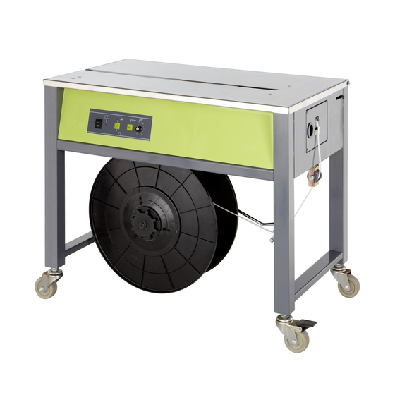
EXTERIOR MACHINE TABLE TOP STRAP CHANNEL PACKAGE CONTROL STOP PANEL FIXED SWIVEL CASTER CASTER FIGURE1. MAJOR COMPONENTS, EXTERIOR ELECTRICAL COMPONENTS STRAPPING HEAD DISPENSER BRAKE DISPENSER ASSEMBLY FLANGE FIGURE2. MAJOR COMPONENTS, FRONT VIEW... -
Page 7: Strapping Head
TENSION MOTOR ADJUST KNOB SLIP COIL OF CLUTCH STRAP ELECTRICAL PANEL DISPENSER BRAKE FIGURE 3. MAJOR COMPONENTS, TOP VIEW TOP COVER ENTRY WELDING EXIT GUIDE CLAMP HOLDING GUIDE FEED TENSION GRIPPER GRIPPER ELECTROMAGNETIC WHEEL WHEEL CLUTCH STRAP GUIDE STRAP TENSIONING ROLLER GEAR REDUCER... -
Page 8: Installation
INSTALLATION SPARE PARTS Installation of the machine, requires that the machine be uncrated, placed in it’s 1 104G001 Micro switch, heavy(LS-1) proper position and secured in place 1 2201210020 Tension spring, short once strap of the proper size is loaded 1 2201011022 Tension spring, long and the power cord is plugged into the... -
Page 9: Operating Instructions
OPERATING INSTRUCTIONS OPERATOR’S CONTROLS MOTOR STOP TIME DIP-SWITCH ADJUSTMENT The motor stop time adjustment on your machine allows the Control Panel. The control panel is located on the user to adjust the motor stop time. Please follow the steps left-hand side of the front panel of the machine. below to adjust the stop time of the motor. - Page 10 For 200mm inner coil diameter, position 2 holes on To operate the EXS-206, proceed as follow: the Reel center claw ( Item 6 ) to #1 and #3 holes of Push the power switch to the “NO” position and the Plastic Flange A (Item 7).
-
Page 11: Operating Adjustments
OPERATING ADJUSTMENTS ADJUSTING TENSION If tension adjustment is required, proceed as follows: Loosen the locking knob at the right hand end of the machine. Turn the knurled knob, located at the rear of the machine, clockwise to increase tension, counterclockwise to decrease tension. -
Page 12: Principles Of Operation
PRINCIPLES OF OPERATION GENERL 1. NEUTRAL POSITION. When the strap is The strapping cycle can be divided into three initially threaded through the machine. It distinct operations: enters the head under the strap guide and a. Grip and tension. over roller D. between two sets of feed and b. - Page 13 2. ENCIRCLING PACKAGE; TRIPPING LS1. Grip and tension is initiated by the operator who encircles the package with the strap and inserts the strap end into the slot of the upper strap guide on the right-hand end of the machine. In doing so, the strap is guided between the gripper portion of the end gripper and anvil then into a slot in the anvil where it makes contact with the start switch detector...
- Page 14 3. TENSION. When LS1 is closed, the electromagnetic clutch energizes and the cam shaft rotates approximately 45 degrees. This small amount of shaft rotation is controlled by LS3, mounted at the right-hand end of the cam shaft. When LS3 closes it de-energizes the electromagnetic clutch and the end gripper will have been moved upward to contain the upper strap beneath the...
- Page 15 4. HOLDING GRIPPER RISES; HOT-KNIFE MOVES INWARD. Momentarily electron tension detector energizes the control circuit to energize the electromagnetic clutch and turn the cam shaft. As the cam shaft turns, the holding gripper rises to contain the other end of the strap beneath the anvil. The tension lever is lowered to release tension and the welding clamp begins to rise.
- Page 16 5. STRAP IS CUT; WELD IS MADE. The welding clamp cuts the strap during it’s upward movement then pushes the upper surface of the lower strap against the lower surface of the hot-knife. It then pushes the hot-knife the lower surface of the upper strap. WELDING CLAMP HOT KNIFE...
- Page 17 6. WELD IS RELEASED; HEAD RETURNS The cam shaft returns to the home TO HOME POSITION. position and closes LS3 and LS5. The hot-knife retracts and the welding clamp electromagnetic clutch pushes the two molten surfaces together, de-energized by LS3 while LS5 welding the strap.
- Page 18 ADJUSTMENTS CLEARANCES Anvil to ensure that anvil operates VERTICAL smoothly a minimum clearance between LOCATION OF the anvil and the left and right guides KEY ESTABLISHES must be maintained. To adjust, proceed HEAD IN HOME SWITCH as follows: POSITION CLOSED 1.
- Page 19 WELDING HOLDING 4. If there is clearance at any point, CLAMP GRIPPER loosen locknuts (1) and (2) and adjust all clearance out at points A, B and C. ADJUSTMENT GRIPPER BRACKET 5. When set, tighten the locknuts. FEED AND TENSION ROLLERS. When the machine is in the neutral position.
-
Page 20: Maintenance
MAINTENANCE GENERAL. Periodic checks of all drive belts for replacement should be made to prevent worn cut or WARNING stretched belts which will affect tension. LUBRICATION. Make sure the machine is clean BEFORE SERVICING MACHINE before applying lubricants to the points shown in the Wear safety glasses with figure below. -
Page 21: Troubleshooting
TROUBLESHOOTING SYMPTOM: Strap jams in strapping head while feeding. CAUSE REMEDY 1. Debris accumulation in feed/tension 1. Disassemble the roller assembly and roller area. remove debris. See Adjustment Section. Figure 24. SYMPTOM: Strap pulls from head before seal and cut-off. 1. - Page 23 TABLE OF CONTENTS TABLE OF CONTENS ---------------------------------------------------------------------------------- 1 FIG.1 WELDING COMPONENT ----------------------------------------------------------------- 2~3 FIG.2-1 DRIVE AND CAM ASSEMBLY --------------------------------------------------------- 4~5 FIG.3 STRAP FEED/TENDION ASSEMBLY ------------------------------------------------- 6~7 FIG.4-4 TENSION ADJUSTMENT AND SENSING ASSEMBLY-------------------------- 8~9 FIG.5 HOT--KNIF AND TENSION LEVER ASSEMBLY---------------------------------- 10~11 FIG.6-3C CABINET COMPONENTS----------------------------------------------------------------- 12~13 FIG.8-2 DISPENSER ASSEMBLY----------------------------------------------------------------- 14~15...
- Page 24 PARTS LIST, FIGURE 1 WELDING COMPONENTS FPS-500-010 Q'TY PART NO. DESCRIPTION 4-01010 END GRIPPER UNIT 4-01020 WELDING CLAMP UNIT 4-01030 HOLDING GRIPPER UNIT 4-01041 SEPARATING PLATE UNIT 4-01050 SEPARATING ARM UNIT 4-01000-110 Main body block 4-01000-120 Guide plate, right hand side 4-01000-130 Guide plate, left hand side 4-01000-140...
- Page 25 113 117 116 128 WARNING All parts must be periodically inspected and replaced if worn or broken.Failure to do this can affect a tool's operation and present a safety hazard. FIGURE1.WELDING COMPONENTS...
- Page 26 PARTS LIST, FIGURE 2 DRIVE AND CAM ASSEMBLIES Q'TY PART NO. DESCRIPTION FPS-500-021 4-02010 REDUCTION GEAR UNIT 4-02021 CAM UNIT 4-02030 MOTOR FAN UNIT,FOR 50HZ 4-02031 MOTOR FAN UNIT,FOR 60HZ 4-02010-110 Pulley 4-02010-120 Reduction gear 4-02020-140 Cam shaft, M17*192 4-02020-150 4-02020-160 4-02020-170 4-02020-180...
- Page 27 20.1 LS-5 LS-3 FIGURE 2. DRIVE AND CAM ASSEMBLIES...
- Page 28 PARTS LIST, FIGURE 3 STRAP FEED/TENSION ASSEMBLY Q'TY PART NO. DESCRIPTION FPS-500-030 4-03011 BEARING HOUSING, UPPER UNIT (ALUMINIUM) 4-03021 BEARING HOUSING, LOWER UNIT (ALUMINIUM) 4-03010-110 Roller shaft 15*85 4-03010-120 Roller shaft 15*66 4-03011-130 Bearing housing, upper (aluminium) 14.1 4-03010-140 Steel roller 14.2 4-03010-142 Steel roller...
- Page 29 FIGURE 3.STRAP FEED/TENSION ASSSEMBLY 14.1 117 130 14.2 120 111...
- Page 30 PARTS LIST, FIGURE 4 TENSION ADJUSTMENT AND SENSING ASSEMBLIES Q'TY PART NO. DESCRIPTION FPS-500-045 4-04010 TIGHTNESS DIRECTOR UNIT 4-04031 TRANSMISSION BRACKET UNIT 4-04000-120 Spring guide 4-04010-130 Tightness adjustment cover 4-04010-140 Tightness adjustment sleeve 4-04010-150 Tightness adjustment nut 4-04010-160 Tightness director 4-04000-170 Tightening pulley 4-04000-190...
- Page 31 FIGURE 4. TENSION ADJUSTMENT AND SENSING ASSEMBLIES For refence only. See Figure8,item 15...
- Page 32 PARTS LIST, FIGURE 5 HOT-KNIFE AND TENSION LEVER ASSEMBLIES FPS-500-050 Q'TY PART NO. DESCRIPTION 4-05010 HEATER ARM UNIT 4-05020 HEATER HEAD UNIT 4-05030 TENSION LEVER UNIT 4-05040 STRAP GUIDE UNIT, ENTRY 4-05050 STRAP GUIDE UNIT, EXIT 4-05010-110 Heater arm side plate 4-05010-120 Heater arm 4-05010-130...
- Page 33 SEE FIGURE 1, ITEM 11 107 109 SEE FIGURE 9-8 ITEM 16 POSITION REFERENCE ONLY.SEE FIGURE 2 FIGURE 5.HOT-KNIFE AND TENSION LEVER ASSEMBLIES...
- Page 34 PARTS LIST, FIGURE 6-2C CABINET COMPONENTS FPS-503-062C Q'TY PART NO. DESCRIPTION 4-06010 PLASTIC ROLLER BRACKET UNIT 4-06200-112 Body 4-06200-121 Door 297E0010 Door magnet 4-06000-151 Plastic package stop 4-06201-160 Stainless steel top cover 229D16075CH-GY Wheel swivel 75mm 17.1 229E16075CH-GY Wheel fixed 75mm 4-06000-180 Door holder 4-06000-191...
- Page 35 OPTION OPTION 17-1 FIGURE 6-2C.CABINT COMPONENTS...
- Page 36 PARTS LIST, FIGURE 8-2 DISPENSER ASSEMBLIES FPS-503-082 Q'TY PART NO. DESCRIPTION 4-08200 REEL BRAKE UNIT 4-08210 PLASTIC FLANGE UNIT 4-08000-110 4-08000-120 Plastic roller 4-08200-130 Roller frame 4-08200-140 Brake belt 4-08200-160 Belt pin 4-08200-170 Brake arm 4-08200-180 Belt holder plate 4-08200-190 Reel shaft 4-07000-110 Plastic flange...
- Page 37 PARTS LIST,FIGURE 9-5 ELECTRICAL COMPONENTS FPS-500-095 Q'TY PART NO. DESCRIPTION 4-09010 SMOKE FAN UNIT 4-09020 INSTANT HEATING TRANSFORMER UNIT,110V Option 4-09041-120 Switch holder 4-09010-132 Fan bracket 4-09010-143 Protect cover 4-09010-151 Protect cover bracket 4-09020-160 Instant heating cable 4-09020-170 Insulating tube 4-09020-180 Transformer foot 4-09000-190...
- Page 38 FIGURE 8-2.DISPENSER ASSEMBLY...
- Page 39 WARNING All parts must be periodically inspected and replaced if worn or broken.Failure to do this can affect a tool's operation and present a safety hazard. FIGURE 9-5.ELECTRICAL COMPONENTS...
- Page 40 PARTS LIST, FIGURE 10-2 CONTROL BOX ASSEMBLY FPS-500-102 Q'TY PART NO. DESCRIPTION 4-10200-110 Control box 4-10200-120 Control box cover PC-FP-30B01 Control PC board asse. FP-30B01 103B1122035 Transformer, 110V/22V 35VA 103B2322035 Transformer, 220-230V/22V 35VA 103B2422035 Transformer, 240V/22V 35VA 115N0630 Fuse seat,(Φ6.3*30) 115ASL-0630-02 Circuit Protector, 2A-6*30mm 110V...
- Page 41 FIGURE10-2. CONTROL BOX ASSEMBLY...
Need help?
Do you have a question about the EXS-206 and is the answer not in the manual?
Questions and answers
after dtrapping there is a long delay before cutting and release
A long delay before cutting and releasing after strapping with the Extend EXS-206 can be caused by the following:
1. LS3 (limit switch) is inoperative or improperly adjusted.
2. Clearance between the welding clamp and end gripper is too great.
3. The cutting surface on the welding clamp is dull.
These issues affect the timing and operation of the sealing and cutting process.
This answer is automatically generated