Advertisement
Quick Links
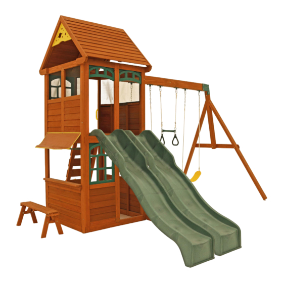
S E L W O O D N E X T G E N E R A T I O N - M I N T
INSTALLATION AND OPERATING INSTRUCTIONS
25' -7" [7.8M]
25' ‐ 7" [7.8M]
4.14M
13'-7"
27'-0"
[8.2M]
27' ‐ 0"
3.48M
[8.2M]
11'-5"
MINT: H = 9ft-5"
10-14 Hrs
TWO PERSON
ASSEMBLY
Europe
The Granary, Weathercock Hill
Chevington, Bury St
Edmunds, Suffolk IP29 5RG
FR: Pour obtenir la notice de montage dans votre langue, cliquez sur www.selwoodproducts.com
DE: Gehen Sie auf www.selwoodproducts.com um die Bauanleitung in thre Sprache zu bekommen.
9409918
WARNING
these instructions often and give them to any future owner of this play system. Manufacturer contact
information provided below.
OBSTACLE FREE SAFETY ZONE - 25'7" (7.8m) x 27' (8.2m) area requires Protective Surfacing. See
Owner's Manual.
MAXIMUM VERTICAL FALL HEIGHT - 6'9"(2.06m)
CAPACITY - 10 Users Maximum, Ages 3 to 10; Weight Limit 110 lbs. (49.9 kg) per child.
RESIDENTIAL HOME USE ONLY. Not intended for public areas such as schools, churches, nurseries, day
cares or parks.
North America
375 Sligo Road West.
P.O. Box 10 Mount Forest
Ontario, Canada N0G 2L1
www.selwood.com
To reduce the risk of serious injury or death, you must
read and follow these instructions. Keep and refer to
Australia
Unit 6/168 - 180 Victoria Road
Marrickville, Sydney NSW
2204
Table of Contents
Part ID . . . . . . . . . . . . . . . . . . . . . . . . . . . . . . . . . . . . . . pg . 2-6
Stop Page . . . . . . . . . . . . . . . . . . . . . . . . . . . . . . . . . . . . . pg . 7
Steps 1 - 30 . . . . . . . . . . . . . . . . . . . . . . . . . . . . . . . pg . 8-54
Fort Guide . . . . . . . . . . . . . . . . . . . . . . . . . . . . . . . pg . 55-56
Registration Page . . . . . . . . . . . . . . . . . . . . . . . . Last Page
Rev 06-16/2016
Advertisement

Related Manuals for SELWOOD Mint


Summary of Contents for SELWOOD Mint
- Page 1 CAPACITY - 10 Users Maximum, Ages 3 to 10; Weight Limit 110 lbs. (49.9 kg) per child. RESIDENTIAL HOME USE ONLY. Not intended for public areas such as schools, churches, nurseries, day MINT: H = 9ft-5" cares or parks. 10-14 Hrs...
- Page 2 2pc. - 2717 - Clock Block 3/4 x 1-3/4 x 9-3/4" 3632717 (19 x 44 x 248mm) 1x - Hole Plug 1x - Hand Grip (16pk) (3329916) Yellow (9320240) 1x - Selwood Window Mesh Set (3750188) 3x -17 x 19" (432 x 483mm) 1x - Frame (9200193) Mesh (9750188) 2pc.
- Page 3 #8 x 2-1/2" 10pc. S3 - Wood Screw - (52043522) (#8 x 64mm) #12 x 2" 13pc. S7 - Pan Screw - (52433620) (#12 x 51mm) #8 x 3" 4pc. S4 - Wood Screw - (52043530) (#8 x 76mm) www.selwood.com...
- Page 4 Hex Bolt 5/16 x 3-3/4" 7pc. G21 - - (53703333) (8 x 95mm) Hex Bolt 5/16 x 4" 3pc. G4 - - (53703340) (8 x 102mm) Hex Bolt 5/16 x 5-1/2" 14pc. G7 - - (53703352) (8 x 140mm) www.selwood.com...
- Page 5 2pc. - 2613 - 2 x 3 x 86-11/16" (51 x 76 x 2202mm) - Heavy SW Post 3632613 1pc. - 2615 - 4 x 4 x 50-15/16" - (76 x 76 x 1294mm) SW Upright 3632615 1pc. - 2614 - 4 x 6 x 88" - (76 x 133 x 2235mm) Engineered Beam3632614 www.selwood.com...
- Page 6 (#8 x 35mm) #8 x 2" (#8 x 51mm) #8 x 7/8" 24pc. S11 - Wood Screw (52043520) 6pc. S0 - Truss Screw (#8 x 22mm) (52933505) #8 x 2-1/2" (#8 x 64mm) 8pc. S3 - Wood Screw (52043522) #8 x 1/2" 8pc. S5 - Pan Screw (#8 x 13mm) (52433502) #8 x 3" (#8 x 76mm) 2pc. S4 - Wood Screw (52043530) 1x - Narrow Angle Bracket (3 Pk) (3200640) Next Generation 48" High Rail Slide EN71 www.selwood.com...
- Page 7 If you have missing, damaged or require replacement parts DO NOT contact your retailer. Please visit www.selwoodproducts.com and select the Parts Centre. You can then complete a quick online order form or make direct contact with the Selwood Products Part Team. www.selwood.com www.selwood.com...
- Page 8 2775 board 2769 2772 Bottom Flush Flush 2771 Fig. 1.2 Wood Parts Hardware End Post 2771 24 x Wood Screw End Post Left 2770 Panel Cross Support 16 x T-nut 2775 Panel Floor Support 2772 Panel BT Frame 2769 www.selwood.com...
- Page 9 It is important to assemble the frame on a flat, smooth surface. D: Turn the assembly over, place (2774) Upright in the middle groves of (2775) Panel Cross Support and (2772) Panel Floor Support then attach all boards with 8 (H9) Hex Bolts (with lock washer and flat washer) connecting to the previously installed t-nuts. (fig. 1.3 and 1.4) E: Repeat steps A-D for a second assembly. Fig. 1.3 2771 2775 2772 2774 Flush 2770 Fig. 1.4 Wood Parts Hardware 16 x Hex Bolt Upright 2774 (lock washer & flat washer) www.selwood.com...
- Page 10 C: Make sure assembly is square then attach with 4 (S30) Wood Screws per board. (fig. 2.2) Fig. 2.1 2768 2769 2769 Fig. 2.2 2770 2769 2768 2769 Flush Bottom Flush 2771 Flush Wood Parts Hardware Panel Floor 2768 12 x Wood Screw Panel BT Frame 2769 End Post T-nut 2771 End Post Left 2770 www.selwood.com...
- Page 11 Step 2: End Wall Prep Part 2 It is important to assemble the frame on a flat, smooth surface. D: Turn the assembly over then attach all boards with 6 (H9) Hex Bolts (with lock washer and flat washer) connecting to the previously installed t-nuts. (fig. 2.3 and 2.4) Fig. 2.3 2771 x 2 per board 2769 2768 2769 2770 Fig. 2.4 Hardware Hex Bolt (lock washer & flat washer) www.selwood.com...
- Page 12 It is important to assemble the frame on a flat, smooth surface. A: Place (2757) LT Post Assembly and (2758) RT Post Assembly on a hard, flat surface with the notches facing down. The top of the post assemblies have the longer notches. (fig. 3.1) B: Tap 1 (TN2) T-nut in the top holes and 1 (TN1) T-nut in the middle and bottom holes. (fig. 3.1). Fig. 3.1 2757 Notice longer notches at the top (both boards) 2758 Bottom Notice shorter notches at the bottom (both boards) Wood Parts Hardware LT Post Assembly 2757 T-nut RT Post Assembly 2758 T-nut www.selwood.com...
- Page 13 Flush Fig. 3.3 Notice Orientation of both (2756) Siding Assemblies. 2758 Fig. 3.4 2630 2768 Flush 2769 2757 Flush Wood Parts Hardware Siding Assembly 2756 12 x Wood Screw SW Top 2630 Panel Floor 2768 Panel BT Frame 2769 www.selwood.com...
- Page 14 Fig. 3.7 2769 Note which bolt holes are used 2778 2778 Wood Parts Hardware Wafer Bolt (flat washer) SW Ground MOD 2778 Diagonal 2607 Hex Bolt (lock washer, flat washer) Hex Bolt (lock washer, flat washer and 1 t-nut) www.selwood.com...
- Page 15 Step 3: Swing Wall Prep Part 4 It is important to assemble the frame on a flat, smooth surface. I: Attach the top board in each (2756) Siding Assembly to (2757) LT Post Assembly and (2758) RT Post Assembly with 4 (S30) Wood Screws per board. (fig. 3.8 and 3.9) J: Attach the remaining boards in each (2756) Siding Assembly to (2757) LT Post Assembly and (2758) RT Post Assembly with 2 (S0) Truss Screws per board. (fig. 3.8 an 3.9) 2756 2758 Fig. 3.8 2756 2757 x 10 x 10 Top Board Remaining Boards Fig. 3.9 Hardware Wood Screw 20 x Truss Screw www.selwood.com...
-
Page 16: Step 4: Frame Assembly
Notice Front overlaps Back Wall Wall overlaps Swing Wall x 4 per side Flush Flush Swing Wall Front Wall Fig. 4.2 Flush Notice grooves face inwards Swing Wall Back Wall Notice counter sunk holes on the outside Flush Hardware Wafer Lag www.selwood.com... - Page 17 Step 4: Frame Assembly Part 2 B: Place End Wall from Step 2 between the Front Wall and Back Wall noticing the wall orientation. The tops and bottoms of the walls should be flush. Make sure the walls are square then using the pilot holes as a guide pre- drill with a 3/16” (4.8 mm) drill bit and fasten the Back Wall to the End Wall and End Wall to the Front Wall with 4 (WL5) Wafer Lags per side. (fig. 4.4) Back Wall Swing Wall Fig. 4.4 Notice Back Wall overlaps End Wall Notice End Wall overlaps Front Wall End Wall Front Wall Hardware Wafer Lag www.selwood.com...
- Page 18 Part 3 C: Loosely attach 1 (2607) Diagonal to left (2778) SW Ground MOD with 1 (H10) Hex Bolt (with lock washer, flat washer and t-nut). (fig. 4.5) D: Place each (2607) Diagonal tight and flush to the front of the Swing Wall then pre-drill pilot holes with a 3/16” (4.8 mm) drill bit and attach each (2607) Diagonal to the Swing Wall with 1 (LS3) Lag Screw (with flat washer) per board, checking that they remain flush to outside edge. (fig. 4.5 and 4.6) Flush Fig. 4.5 Flush 2607 (hidden) 2607 Swing Wall 2778 Fig. 4.6 2607 2607 Swing Wall Hardware Wood Parts Hex Bolt (lock washer, flat washer, t-nut) Diagonal 2607 Lag Screw (flat washer) www.selwood.com...
- Page 19 Step 5: Floor Assembly Part 1 A: From inside of the assembly centre (2608) Floor Joist over the pilot holes in both (2768) Panel Floors in the Swing and End Walls, measure 5/8” (15.9 mm) down from the top of boards then attach (2608) Floor Joist to each board using the left and centre holes with 2 (S4) Wood Screws per board. (fig.5.1, 5.2, 5.3 and 5.4) Swing Wall Fig. 5.1 2608 2768 2768 End Wall Fig. 5.2 5/8” (15.9 mm) Fig. 5.4 Fig. 5.3 2608 2768 Swing Wall Notice holes used End Wall Hardware Wood Parts Floor Joist Wood Screw 2608 www.selwood.com...
- Page 20 Step 5: Floor Assembly Part 2 B: On the inside of both the Front and Back Walls loosely attach 1 (2777) Side Joist MOD to each (2772) Panel Floor Support with 2 (H11) Hex Bolts (with lock washer, flat washer and t-nut) as shown in fig. 5.5. Make sure both (2777) Side Joist MODs are level with (2608) Floor Joist. Back Wall Fig. 5.5 2772 2777 2777 2772 2608 Front Wall Hardware Wood Parts Side Joist MOD Hex Bolt 2777 (lock washer, flat washer, t-nut) www.selwood.com...
- Page 21 Step 5: Floor Assembly Part 3 C: Fasten each (2777) Side Joist MOD to each (2772) Panel Floor Support with 4 (S3) Wood Screws per board as shown in fig. 5.6. D: Tighten all (H11) Hex Bolts in both (2777) Side Joist MOD. Fig. 5.6 2777 2772 Hardware Wood Screw www.selwood.com...
- Page 22 Step 5: Floor Assembly Part 4 E: Starting at the Swing Wall place (2648) Floor Board followed by 8 (2609) Floor Boards. Make sure all boards are evenly spaced then attach to (2608) Floor Joist and each (2777) Side Joist MOD with 5 (S20) Wood Screws per board. (fig. 5.7 and 5.8) Swing Wall 2609 Fig. 5.7 2648 2768 Fig. 5.8 x 5 per board Wall removed for 2777 clarity 2608 2777 Hardware Wood Parts Floor Board 45 x Wood Screw 2648 Floor Board 2609 www.selwood.com...
-
Page 23: Step 6: Swing Beam Assembly
Other Parts Wood Parts 12 x Hex Bolt (flat washer x 2, lock nut) 6 x Swing Hangers Engineered Beam 2614 Hex Bolt (flat washer x 2, lock nut) 2 x L-Beam Bracket Wafer Bolt (flat washer & t-nut) www.selwood.com... - Page 24 2616 the angle 2615 2613 Wood Parts Hardware Hex Bolt (lock washer, flat washer, t-nut) Heavy SW Post 2613 SW Upright Hex Bolt (lock washer, flat washer, t-nut) 2615 SW Support Wafer Bolt (flat washer & t-nut) 2616 www.selwood.com...
- Page 25 Step 8: Attach Swing End to Swing Beam A: Place Swing End Assembly against Swing Beam Assembly then place 1 Beam Bracket on each side of the assembly (they are specific for left and right side) and attach with 5 (G21) Hex Bolts (with 2 flat washers and 1 lock nut). (fig. 8.1 and 8.2) Fig. 8.1 Swing Beam Assembly Beam Bracket Swing Beam Swing End Assembly Assembly Fig. 8.2 Swing End Assembly Hardware Other Parts 2 x Beam Bracket (Left/Right) Hex Bolt (flat washer x 2, lock nut) www.selwood.com...
- Page 26 Step 9: Attach Swing Assembly To Fort A: Place Swing Assembly against top of (2630) SW Top, make sure assembly is level then attach from inside the fort assembly into each L-Beam Bracket with 4 (G8) Hex Bolts (with 2 flat washers and 1 lock nut). (fig. 9.1) L-Beam 2630 Bracket Fig. 9.1 Swing Assembly Hardware Hex Bolt (flat washer x 2, lock nut) www.selwood.com...
- Page 27 Wall Fig. 10.2 Front End Wall Fig. 10.1 Rebar Ground Stake 2607 Fig. 10.3 2613 2607 SEE FRONT COVER Rebar FOR SAFETY CLEARANCE Ground Stake Hardware Other Parts Pan Screw 5 x Rebar Ground Stake www.selwood.com...
- Page 28 End Wall Front Wall Jamb Jamb 2601 Mount Mount 2602 Centred x 4 per Jamb Mount 2601 Centred x 4 per Jamb 2602 Mount Hardware Wood Parts Other Parts Lower Jamb 4 x Jamb Mount 16 x Truss Screw 2601 Upper Jamb 2602 www.selwood.com...
- Page 29 For (2649) Lower Window Insert and (2655) Upper Window Insert - 9 x (S0) Truss Screws per insert. For (2665) Half Wall Insert, (649A) Short Half Walls and MOD 3-Pane Transoms - 4 x (S0) Truss Screws per insert. Inside View 2649 2655 2649 2655 Tight www.selwood.com...
- Page 30 Step 12: How to Install Inserts - Window and Wall Inserts Part 2 Inside Views MOD 3-Pane Transom Tight 649A 2665 Tight Tight REV. DWG. NO. SCALE:1:50 SHEET 2 OF 2 www.selwood.com...
- Page 31 Base Clock, Clock Subset (includes minute and hour hands, clock adapter and clock screw), 2 (2717) Clock Blocks and 4 x (S20) Wood Screws. To assemble Clock insert the Clock Adapter from the back of the Base Clock, place the Hour Hand over the Clock Adapter making sure they are lined up properly. Press the Minute Hand over the Hour Hand and connect with Clock Screw. Attach assembled Clock through panel and into each (2717) Clock Block with 4 (S20) Wood Screws. Do not over tighten screws. Outside View Side View Hour Hand Clock Adapter Clock Screw Base Clock Minute Hand Base Clock 2717 Panel Inside View 2717 www.selwood.com...
- Page 32 Wood Parts Hardware Other Parts 5 x Rocks (3 green/2 yellow) 24 x Wood Screw Access Board 2779 Pan Screw Rk Board B 2781 Pan Bolt Rk Board A 2780 (lock washer, flat washer & barrel nut) Rock Rail 2776 www.selwood.com...
- Page 33 Note: Make sure (2776) Rock Rails do not cover the bolt head, move assembly over so it is tight to the bolt head. (fig. 15.1 and 15.2) Fig. 15.2 Panel Fig. 15.1 Flush Bolt Head 2776 2776 Fig. 15.3 Flush 2779 2776 2776 Wood Parts Hardware Access Board Wood Screw 2779 Wood Screw www.selwood.com...
- Page 34 13” (330 mm) into ground. Digging or driving stakes can be dangerous if you do not check first for under-ground wiring, cables or gas lines. 2776 Fig. 15.5 Fig. 15.4 2776 Rebar Ground Stake Hardware Other Parts 1 x Rebar Ground Stake Pan Screw www.selwood.com...
- Page 35 Step 16: Attach Hand Grip to Fort A: Measure 6” (152.4 mm) from the top of the floor boards on the left hand side of the Rock Board, pre-drill with a 1/8” (3.2 mm) drill bit then attach 1 Play Handle with 2 (WL3) Wafer Lags to the Back Wall. (fig. 16.1) Play Handle Fig. 16.1 6” (152.4 Hardware Other Parts Wafer Lag 1 x Play Handle www.selwood.com...
- Page 36 Step 17: Cafe Table Assembly A: Place (2612) Table Support flush to the notched out ends of (2611) Table Top and attach with 4 (S7) Pan Screws as shown in fig. 17.1. B: Place Table Top Assembly tight in the opening of End Wall with the overhang on the outside of the assembly as shown in fig. 17.2 and in the Fort Guide then attach (2612) Table Support to the End Wall posts with 2 (S3) Wood Screws. Fig. 17.1 2612 Flush 2611 Tight Flush Fig. 17.2 Outside View 2611 Tight 2612 End Wall Wood Parts Hardware Pan Screw Table Support 2612 Wood Screw Table Top 2611 www.selwood.com...
- Page 37 5” Start on this side 381 mm 79 mm 15” 3-1/8” 38.1 1-1/2” 2770 2771 Cafe Canopy Cafe Canopy End Wall Frame x 1 per side Hardware Other Parts Pan Screw (#8 flat washer) 1 x Cafe Canopy Frame Pan Screw 1 x Cafe Canopy www.selwood.com...
- Page 38 Step 19: Roof Support Assembly A: Attach 1 (2760) Roof Support to a second (2760) Roof Support at peak using 1 (S4) Wood Screw. Repeat this step so there are 2 Roof Support Assemblies. (fig. 19.1 and 19.2) Fig. 19.1 Roof Support Assembly 2760 Fig. 19.2 2760 Hardware Wood Parts Wood Screw Roof Support 2760 www.selwood.com...
- Page 39 Make sure panels are tight Fig. 20.2 to each other 2753 2751 2752 2751 2751 2761 Flush x 4 per board Wood Parts Hardware MOD Roof Bottom Wood Screw 2751 MOD Roof Front 2752 MOD Roof Back 2753 Roof Sleeper C 2761 www.selwood.com...
-
Page 40: Step 21: Roof Assembly
Step 21: Roof Assembly Part 1 A: Place Front Roof Panel against Back Roof Panel so the tops form a peak then tight to the inside edge of the outside slats attach 1 Narrow Angle Bracket per slat with 2 (S0) Truss Screws per bracket. (fig. 21.1 and 21.2) B: Attach the third Narrow Angle Bracket centred on the middle slat with 2 (S0) Truss Screws. (fig. 21.1 and 21.3) Centred Fig. 21.3 Narrow Angle Bracket Flush Fig. 21.1 Narrow Angle Bracket Fig. 21.2 Flush x 2 per bracket Flush Back Roof Front Roof Panel Panel Hardware Other Parts Truss Screw 3 x Narrow Angle Bracket www.selwood.com... - Page 41 Step 21: Roof Assembly Part 2 C: Place 1 Roof Support Assembly against one side so the peaks meet and the ends of the roof supports are flush with the ends of the roof panels. Attach with 8 (S11) Wood Screws. (fig. 21.4) D: Attach the second Roof Support Assembly on the opposite side, peaks to meet and ends are flush with 8 (S11) Wood Screws. (fig. 21.4) Fig. 21.4 Roof Support Assembly Flush Flush Back Roof Panel Front Roof Panel Flush Flush (hidden) Roof Support Assembly Hardware 16 x Wood Screw www.selwood.com...
- Page 42 Step 22: Attach Sky Gable A: Attach 1 Sky Gable to the inside of the (2760) Roof Supports on each side of the Roof Assembly with 4 (S5) Pan Screws per Sky Gable. (fig. 22.1 and 22.2) Fig. 22.1 Roof Assembly Sky Gable 2760 Fig. 22.2 Inside View Sky Gable 2760 Hardware Other Parts Pan Screw 2 x Sky Gable www.selwood.com...
- Page 43 Step 23: Attach Roof Ends Part 1 A: On the End Wall remove the 2 outside (H9) Hex Bolts attached at the top of the assembly from Step 2, Part 2. Leave the (TN1) T-nuts in. The (FW1) Flat Washers and (LW1) Lock Washers will be used in Step B. (fig. 23.1) Fig. 23.1 End Wall Remove these bolts on the End Wall, keeping lock washers and flat washers for next step. Do not remove the t-nuts. www.selwood.com...
- Page 44 Fig. 23.2 2759 2759 Swing Wall 2759 Keep bolts loose Back Front Flush Fig. 23.4 Wall Wall Right Side 2769 2759 End Wall 2769 2759 2759 Fig. 23.5 2759 Flush 2769 2759 Wood Parts Hardware Roof End Hex Bolt 2759 www.selwood.com...
- Page 45 Step 23: Attach Roof Ends Part 3 C: Measure overhang so it is 4-7/8” (124 mm) then attach with 2 (S11) Wood Screws and 1 (S3) Wood Screw per (2759) Roof End. Tighten the bolts. (fig. 23.6, 23.7 and 23.8) Fig. 23.6 Top View 2759 (124 mm) Front and Back Walls x 2 per board End Wall Fig. 23.8 Fig. 23.7 Right Side Left Side 2759 2759 Hardware Wood Screw Wood Screw www.selwood.com...
- Page 46 End. Notice which holes are to be used. (fig. 23.9, 23.10, and 23.11) 2630 Fig. 23.9 Flush Flush 2759 Right Side Left Side 2759 Swing Wall Fig. 23.10 Fig. 23.11 2759 2759 Left Side Right Side 4-7/8” 4-7/8” Overhang Overhang 2630 Hardware Wood Parts Wood Screw Roof End 2759 Wood Screw www.selwood.com...
- Page 47 Step 24: Attach Roof Assembly to Fort A: With 2 people on the ground and at least 1 person in the fort, lift the Roof Assembly up and over the front side of the fort. Guide the Roof Assembly onto the fort so all four (2760) Roof Supports sit flush to the front and outside edges of (2759) Roof Ends. (fig. 24.1) B: Attach (2760) Roof Supports to (2759) Roof Ends with 1 (S3) Wood Screw per support. (fig. 24.1) Roof Assembly Fig. 24.1 2760 2760 Front Wall Flush Flush 2759 2759 Back Wall Flush 2759 Hardware Wood Screw www.selwood.com...
- Page 48 Step 25: Attach Slide to Fort A: Place Slides in the centre of the openings at the front of the fort as shown in the Fort Guide, pre-drill with a 1/8” (3.2 mm) drill bit then attach slide to fort through the (2772) Panel Floor Support using 3 (S7) Pan Screws per slide. (fig. 25.1 and 25.2) Fig. 25.1 Slide Fig. 25.2 2772 Front Wall 2772 Slide Hardware Other Parts Pan Screw 2 x Slide www.selwood.com...
- Page 49 Acro Bar Fig. 26.2 Threaded Clip Threaded Clip Acro Rope Fig. 26.3 EN71 Acro Handles Threaded Clips attach to Acro Ropes Threaded Clip Other Parts 2 x Belt Swings 1 x Acro Bar 2 x Acro Handle 2 x Acro Rope EN71 4 x Threaded Clips www.selwood.com...
-
Page 50: Step 27: Bench Assembly
Step 27: Bench Assembly A: Open the (2658) Folding Bench Assembly. (fig. 27.1, 27.2 and 27.3) B: Make sure assembly is level then secure with 2 (H1) Hex Bolts (with lock washer, flat washer and t-nut) per side. (fig. 27.4) C: Tighten the top screws in all 4 Bench Legs. (fig. 27.4) Bench Legs Fig. 27.3 2658 Fig. 27.2 Fig. 27.1 Bench Legs Fig. 27.4 Tighten these screws - all 4 legs Hardware Wood Parts Hex Bolt Folding Bench 2658 (lock washer, flat washer, t-nut) www.selwood.com... - Page 51 Step 28: Attach Window Mesh - Large Part 1 A: From inside the assembly place the Window Mesh - Large over the upper opening in the Swing Wall, make sure the mesh is smooth and tight then attach all four corners to (2757) LT Post Assembly and (2758) RT Post Assembly with 4 (S5) Pan Screws (with #8 flat washers). (fig. 28.1) Fig. 28.1 Swing Wall Inside View 2758 2757 Window Mesh - Large Hardware Other Parts Pan Screw (#8 flat washer) 1 x Window Mesh - Large www.selwood.com...
- Page 52 Step 28: Attach Window Mesh - Large Part 2 B: Along each side measure 4-1/2” (114 mm) down from the top screws and the same dimension up from the bottom screws then attach 2 (S5) Pan Screws (with #8 flat washer) per side to (2757) LT Post Assembly and (2758) RT Post Assembly. (fig. 28.2) C: Along the top and bottom measure 6-3/8” (162 mm) in from the corner screws on one side then attach 5 (S5) Pan Screws (with #8 flat washer) to (2630) SW Top and (2756) Siding Assembly. Each screw to be the same dimension apart. (fig. 28.2) Fig. 28.2 2757 2630 2758 2756 x 14 x 14 Hardware 14 x Pan Screw (#8 flat washer) www.selwood.com...
- Page 53 Step 29: Attach Window Mesh - Small A: From inside the assembly place 2 Window Mesh - Small over the upper openings in the End Wall, make sure the mesh is smooth and tight then attach all four corners to the posts, (2602) Upper Jamb and (2769) Panel BT Frame with 4 (S5) Pan Screws (with #8 flat washers) per mesh. (fig. 29.1) B: Along each side measure 5-1/2” (140 mm) down from the top screws and the same dimension up from the bottom screws then attach 2 (S5) Pan Screws (with #8 flat washer) per side, per mesh. (fig. 29.1) C: Along the top and bottom measure 6” (152 mm) in from the corner screws on one side then attach 2 (S5) Pan Screws (with #8 flat washer) per mesh. Each screw to be the same dimension apart. (fig. 29.1) 2775 Fig. 29.1 x 12 Start at all four corners Window Mesh - Small x 12 2602 2771 649A Hardware Other Parts 24 x Pan Screw (#8 flat washer) 2 x Window Mesh - Small www.selwood.com...
-
Page 54: Step 30: Final Step
Step 30: Final Step A: Inspect entire play centre and insert hole plugs into all unused holes. See fig. 30.1 and 30.2 for an example. B: Check entire play centre for bolts protruding beyond t-nuts. Use extra Washers to eliminate this condition. Fig. 30.2 Unused Hole Fig. 30.1 Hole Plug Hole Plug Hardware 10 x Hole Plugs www.selwood.com... - Page 55 Fort Guide: MINT MOD 3-Pane Transom (Step 12) Front Wall (Step 1) Slide 2601 (Step 25) (Step 11) 2649 (Step 12) MOD 3-Pane Transom (Step 12) Slide Position (Step 25) 2601 (Step 11) 2649 (Step 12) Front Wall Window Mesh Small (Step 29) (Step 12) 649A End Wall (Step 2) Cafe Canopy (Step 18) 2665...
- Page 56 Back Wall Rock Wall (Step 14 -15) Swing Swing Assembly Assembly (Step 6-9) Roof Assembly Window Mesh - with Sky Gables Large (Step 28) (Step 19-24) Maximum Number of Users: 10 25’ -7” [7.8M] 25' ‐ 7" [7.8M] Swing Wall (Step 3) 4.14M 13'-7" 27’-0” 27' ‐ 0" [8.2M] 3.48M [8.2M] 11'-5" Swing Wall MINT: H = 9ft-5" www.selwood.com...
- Page 57 NOTES NOTES www.selwood.com...
Need help?
Do you have a question about the Mint and is the answer not in the manual?
Questions and answers