Advertisement
Quick Links
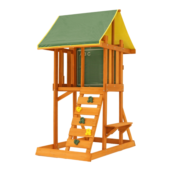
MEADOWSIDE II PLAY SYSTEM - F24021E
INSTALLATION AND OPERATING INSTRUCTIONS
M e a d o w s i d e I I
16'2"
4927.6
4' 2"
1270
5'4"
1626
4 - 8 Hrs
Two person
assembly
Europe
The Granary, Weathercock Hill
Chevington, Bury St
Edmunds, Suffolk IP29 5RG
FR: Pour obtenir la notice de montage dans votre langue, cliquez sur www.selwoodproducts.com
DE: Gehen Sie auf www.selwoodproducts.com um die Bauanleitung in thre Sprache zu bekommen.
3404021E
WARNING
and give them to any future owner of this play system. Manufacturer contact information provided below.
OBSTACLE FREE SAFETY ZONE - 16' 2" x 17'4" (4.93 x 5.28 m) area requires Protective Surfacing. See page 3.
MAXIMUM VERTICAL FALL HEIGHT - 6' (1.8 m)
CAPACITY - 4 Users Maximum, Ages 3 to 10; Weight Limit 110 lbs. (49.9 kg) per child.
17'4"
5283.2
RESIDENTIAL HOME USE ONLY. Not intended for public areas such as schools, churches, nurseries, day cares or parks.
North America
375 Sligo Road West.
P.O. Box 10 Mount Forest
Ontario, Canada N0G 2L1
www.selwoodproducts.com
To reduce the risk of serious injury or death, you must read and
follow these instructions. Keep and refer to these instructions often
Australia
Unit 6/168 - 180 Victoria Road
Marrickville, Sydney NSW 2204
Table of Contents
Warnings and Safe Play Instructions. . . . . . . . . . . . . . . pg. 2
Protective Surfacing Guidelines. . . . . . . . . . . . . . . . . . . pg. 3
Instructions for Proper Maintenance . . . . . . . . . . . . . . . pg. 4
About Our Wood - Limited Warranty . . . . . . . . . . . . . . pg. 5
Keys to Assembly Success . . . . . . . . . . . . . . . . . . . . . . pg. 6
Metric Conversion Sheets . . . . . . . . . . . . . . . . . . . . . pg. 7,8
Part ID . . . . . . . . . . . . . . . . . . . . . . . . . . . . . . . . . . . . . . . pg. 9
Rev 20/09/2016
Advertisement

Related Manuals for SELWOOD MEADOWSIDE II F24021E


Summary of Contents for SELWOOD MEADOWSIDE II F24021E
-
Page 1: Table Of Contents
MEADOWSIDE II PLAY SYSTEM – F24021E INSTALLATION AND OPERATING INSTRUCTIONS M e a d o w s i d e I I WARNING 16'2" To reduce the risk of serious injury or death, you must read and 4927.6 follow these instructions. Keep and refer to these instructions often and give them to any future owner of this play system. -
Page 2: Warnings And Safe Play Instructions
Warnings and Safe Play Instructions CONTINUOUS ADULT SUPERVISION REQUIRED. Most serious injuries and deaths on playground equipment have occurred while children were unsupervised! Our products are designed to meet mandatory and voluntary safety standards. Complying with all warnings and recommendations in these instructions will reduce the risk of serious or fatal injury to children using this play system. -
Page 3: Protective Surfacing Guidelines
Denotes Use Zone with Protective Surfacing 1.83 m (6 ft) 1.83 m (6 ft) 1.83 m (6 ft) 1.83 m (6 ft) Use Zone for Single-Axis Swings Use Zone for Multi-Axis Swings From the CPSC Outdoor Home Playground Safety Handbook. At http://www.playgroundregs.com/resources/CPSC%20324.pdf www.selwood.com support@cedarsummitplay.com www.selwoodproducts.com... -
Page 4: Instructions For Proper Maintenance
Instructions for Proper Maintenance Your Big Backyard Play System is designed and constructed of quality materials with your child’s safety in mind. As with all outdoor products used by children, it will weather and wear. To maximize the enjoyment, safety and life of your Play Set, it is important that you, the owner, properly maintain it. -
Page 5: About Our Wood - Limited Warranty
Selwood Products Limited Warranty Selwood Products states that the product is free from defect in materials and workmanship for a period of one (1) year from the original date of purchase. This one (1) year warranty covers all parts including wood, hardware, and accessories. All wood carries a ten (10) year warranty against rot and decay. -
Page 6: Keys To Assembly Success
Keys to Assembly Success Tools Required Shovel Measuring Drill (1/8” Safety Hammer Ratchet 1/2”, Level #2 & #3 Phillips Square Step Tape 3/16” Bit) Glasses 7/16” & 9/16” or Robertson Ruler Ladder Part Identification Key 1234 Post 2 x 4 x 83” On each page, you will find the parts and quantities required to complete the assembly step illustrated on that page. -
Page 7: Metric Conversion Sheets
www.selwoodproducts.com... - Page 8 www.selwoodproducts.com...
-
Page 9: Part Id
Part Identification (Reduced Part Size) (2) CE Gap Board 1 x 6 x 23-1/2" Nominal Size Actual Size 1774 3631774 ⅜ 1½" x 5 " 2" x 6" ⅜ ⅜ " x 3 " 2" x 4" (4) Floor Board 1 x 6 x 23-1/2" ⅜... - Page 10 Part Identification (Reduced Part Size) Nominal Size (2) Side Top 1 x 4 x 51-1/2" Actual Size 2445 ⅜ ⅜ " x 3 " 3642445 2" x 4" ⅜ " x 2½" 2" x 3" 2" x 2" 1½" x 1½" 1"...
- Page 11 HARDWARE ID (Actual Size) 9277220 (26) Hex Bolt 1/4 x 2" 1/4" Lock Washer - 1/4" Flat Washer - 1/4" T-Nut 9277230 (1) Hex Bolt 1/4 x 3" 1/4" Lock Washer - 1/4" Flat Washer - 1/4" T-Nut 9277232 (1) Hex Bolt 1/4 x 3-1/2" 1/4"...
- Page 12 HARDWARE ID (Actual Size) (42) Pan Screw #8 x 1/2" (9264504) (17) (16) Wood Screw #8 x 1-1/8" (9260514) 3/16" Flat Washer (9251100) 5/16" Flat Washer (9251300) (81) Wood Screw #8 x 1-1/2" (9260512) (18) Wood Screw #8 x 1-3/4" (9260513) (41) 1/4"...
- Page 13 Step 1: Inventory Parts - Read This Before Starting Assembly STOP STOP STOP STOP This is the time for you to inventory all your hardware, wood and accessories, referencing the parts identification sheets. This will assist you with your assembly. •...
- Page 14 Step 2: Cafe Side Wall Assembly A: Loosely attach (1792) Lower Side and (2448) SW Floor with 4 (H2) 1/4 x 2” Hex Bolts (with lock washer, flat washer and t-nut) per board; and (2445) Side Top using 2 (H2) 1/4 x 2” Hex Bolts (with lock washer, flat washer and t-nut) to 2 (2469) Posts as shown in fig.
- Page 15 Step 3: Swing Side Wall Assembly A: Loosely attach (1792) Lower Side and (2448) SW Floor with 4 (H2) 1/4 x 2” Hex Bolts (with lock washer, flat washer and t-nut) per board; and (2445) Side Top using 2 (H2) 1/4 x 2” Hex Bolts (with lock washer, flat washer and t-nut) to 2 (2469) Posts as shown in fig.
- Page 16 Step 4: Fort Frame Assembly Part 1 A: On the front of the assembly, side without the (0369) Lower Diagonals, loosely attach (1764) Floor Front to both (2469) Posts, noticing the bolt holes are towards the bottom of the board, with 2 (H6) 1/4 x 4-3/4” Hex Bolts (with lock washer, flat washer and t-nut).
- Page 17 Step 4: Fort Frame Assembly Part 2 C: From inside the assembly attach (1761) Side Joist to (2463) Floor Back with 2 (H2) 1/4 x 2” Hex Bolts (with lock washer, flat washer and t-nut) in the outside holes, as shown in fig. 4.3 and 4.4. 1/4”...
- Page 18 Step 5: Attach Chalk Wall Tarp to Fort Part 1 A: On the back of the assembly, from the inside, tuck Chalk Wall Tarp between (2463) Floor Back and both (2469) Posts. Align Chalk Wall Tarp to edge of both (2469) Posts and place just below second hole from the top of the posts.
- Page 19 Step 5: Attach Chalk Wall Tarp to Fort Part 2 E: On the outside of the Chalk Wall Tarp attach (1795) Top Back to each (2469) Post with 2 (H4) 1/4 x 4” Hex Bolts (with lock washer, flat washer and t-nut) in the top holes and 2 (S7) #12 x 2” Pan Screws (with 3/16” flat washer) in the bottom holes.
- Page 20 Step 5: Attach Chalk Wall Tarp to Fort Part 3 G: From inside the assembly attach Chalk Wall Tarp to (1795) Top Back, 1/2” in from the edge of the tarp, with 4 evenly spaced (S5) #8 x 1/2” Pan Screws (with #8 flat washer). (fig. 5.4) H: Measure 1”...
- Page 21 Step 6: Attach Acro Top to Fort A: On the front of the assembly, on the inside flush to the tops of both (2469) Posts, attach (2829) Front Top with 2 (H4) 1/4 x 4” Hex Bolts (with lock washer, flat washer and t-nut) in the top holes and 2 (S7) #12 x 2” Pan Screws (with 3/16”...
- Page 22 Step 7: Attach Lower Back to Fort A: Place (2449) Lower Back flush to the bottom of each (0369) Lower Diagonal so the ends are flush with the outside face of each (1792) Lower Side, then attach with 4 (S7) #12 x 2” Pan Screws (with 3/16” flat washer). (fig.
- Page 23 Step 8: Attach Centre Divider to Fort A: With the notched end at the bottom and tight to (1764) Floor Front attach (1747) Centre Divider to (2829) Front Top with 1 (H12) 1/4 x 3” Hex Bolt (with lock washer, flat washer and t-nut) installed from the outside of the assembly and to (1764) Floor Front with 1 (H13) 1/4 x 3-1/2”...
- Page 24 Step 9: Rock Wall Frame Assembly A: Attach (1766) Corner Block flush to the bottom and side of 1 (2470) Rock Rail with 2 (S4) #8 x 3” Wood Screws, as shown in fig. 9.1. Notice which direction the angled edge of (2470) Rock Rail faces. B: Place Rock Rail Assembly, from Step 9A 5/8”...
- Page 25 Step 10: Attach Gusset to Fort A: Make sure the assembly is square before proceeding. B: From the inside of the assembly, attach (0312) Gusset flush to the outside edge of (2469) Post on the Swing Wall using 2 (S4) #8 x 3” Wood Screws. The other end of the gusset should be tight against (1764) Floor Front. (fig.
- Page 26 Step 11: Rock Wall Assembly A: Attach (1779) CE Access Board flush to the top and outside edges of each (2470) Rock Rail with 4 (S2) #8 x 1-1/2” Wood Screws. (fig. 11.1 and 11.2) B: Below (1779) CE Access Board stagger 3 (1777) CE Rock Board B and 2 (1778) CE Rock Board A, making sure they are evenly spaced with a minimum 2-1/4”...
- Page 27 Step 12: Attach Rocks to Rock Board A: Place 1 rock on each (1777) and (1778) CE Rock Board A & B (fig. 12.1 and 12.2) and attach using 1 (PB2) 1/4 x 1-1/4” Pan Bolt (with lock washer, flat washer and barrel nut) and 1 (S10) #8 x 1” Pan Screw per rock. The rocks can be attached in any order.
- Page 28 Step 13: Floor Assembly Part 1 A: From inside of the assembly, measure 3-1/8” down from the top of each (2448) SW Floor then attach (1763) Floor Joist to each board with 1 (S3) #8 x 2-1/2” Wood Screw per end. (fig. 13.1 and 13.2) B: Tight to both (2448) SW Walls install 1 (1774) CE Gap Board to each end of the assembly attaching to (1764) Floor Front, (1761) Side Joist and (1763) Floor Joist using 5 (S2) #8 x 1-1/2”...
- Page 29 Step 13: Floor Assembly Part 2 D: In between (1774) CE Gap Boards and (1780) Center Board place 4 (1776) Floor Boards making sure all boards are evenly spaced. Attach to (1764) Floor Front, (1761) Side Joist and (1763) Floor Joist using 5 (S2) #8 x 1-1/2”...
- Page 30 Step 14: Attach Roof Supports to Fort A: From inside the assembly, on the Cafe Side, attach (2451) Tarp Support to (2445) Side Top and (2448) SW Floor with 2 (H2) 1/4 x 2” Hex Bolts (with lock washer, flat washer and t-nut). The support should be tight to the floor boards.
- Page 31 Step 15: Attach SL Spacer to Fort A: On the Front of the assembly, tight to (1779) CE Access Board and flush to the top of the floor boards, attach (1782) SL Spacer to (1761) Side Joist with 4 (S3) #8 x 2-1/2” Wood Screws. (fig 15.1 and 15.2) Fig.
- Page 32 Step 16: Attach Wall Boards to Fort A: On the Cafe Side centre 1 (1829) Cedar Wall between (2451) Tarp Support and (2469) Post on the Back side and attach to (2445) Side Top and (2448) SW Floor with 4 (S1) #8 x 1-1/8” Wood Screws. (fig 16.1) B: On the Cafe Side centre 1 (5265) Cedar Wall between (2451) Tarp Support and (2469) Post on the Front side and attach to (2445) Side Top and (2448) SW Floor with 4 (S1) #8 x 1-1/8”...
- Page 33 Step 17: Roof Frame Assembly A: Pre-drill pilot holes for the screws using a 1/8” drill bit, centred on the ends of each (2445) Side Top, then attach (1796) Top Ends to each (2445) Side Top with 4 (S2) #8 x 1-1/2” Wood Screws per board. Make sure the top of (1796) Top Ends are flush to the tops of each of (2445) Side Top.
- Page 34 Step 18: Attach Canopy to Roof Frame A: Place Canopy over (1900) Ridge making sure bottom edges of tarp are even on both sides of assembly. (fig. 18.1) B: Secure one side by attaching Canopy to 1 (1796) Top End using 6 evenly spaced (S5) #8 x 1/2” Pan Screws (with #8 flat washer).
- Page 35 Step 19: Attach Slide to Fort (Slide sold separately) Note: Pre-drill all holes using a 1/8” drill bit before installing the pan screws. A: On the front of the assembly place Slide in the centre between (2469) Post and (1747) Centre Divider, flush to the inside edge of (1782) SL Spacer.
- Page 36 Step 20: Bench Assembly Part 1 A: On the Cafe Side measure 20” up from the ground on each (2469) Post then attach 1 (2827) Bench Brace to each (2469) Post with 3 (S3) #8 x 2-1/2” Wood Screws per brace. (fig. 20.1 and 20.2) Fig.
- Page 37 Step 20: Bench Assembly Part 2 B: Tight to each (2469) Post and each (2827) Bench Brace place 1 (2828) Bench Gusset flush to the end of each brace then attach to (2827) Bench Brace with 2 (S3) #8 x 2-1/2” Wood Screws per gusset and to (2469) Post with 1 (S3) #8 x 2-1/2”...
- Page 38 Step 20: Bench Assembly Part 3 C: Place 2 (2826) Bench Tops on top of (2827) Bench Braces so they are tight together and the front board is flush to the angled edges of (2827) Bench Braces and (2828) Bench Gussets. Pilot holes to be centred over each (2827) Bench Brace.
- Page 39 Step 21: Attach Ground Stakes MOVE FORT TO FINAL LOCATION. FINAL LOCATION MUST BE LEVEL GROUND Warning! To prevent tipping and avoid potential injury, stakes must be driven 10-1/2” into ground. Digging or driving stakes can be dangerous if you do not check first for underground wiring, cables or gas lines. A: Drive 3 (0318) Ground Stakes 10-1/2”...
- Page 40 Step 22: Attach SW Spacer to Fort If Bolt protrudes Warning! beyond T-Nut Check entire play centre for bolts protruding beyond T-Nuts. Use an extra Use extra washers to eliminate this Flat W asher condition. A: From inside the assembly, tight to the top of (2448) SW Floor attach (2467) SW Spacer to (2447) SW Mount with 2 (S2) #8 x 1-1/2”...
- Page 41 Step 23: Optional SW Mount Installation If you have purchased a 2- or 3-Position Monkey Ladder Swing to add to your fort complete this step. If you have purchased 3-Position Swing II, refer to that manual. A: On the Back of the Swing Side remove the 2 (H2) 1/4 x 2” Hex Bolts (with lock washer and flat washer) which attach the (2445) Side Top and (2448) SW Floor to the (2469) Post.
- Page 42 Final Step: Attach I.D. Plaque ATTACH THIS WARNING & I.D. PLAQUE TO A PROMINENT LOCATION ON YOUR PLAY EQUIPMENT! (Fort or Swing Post) This provides warnings concerning safety and important contact information. A Tracking Number is provided to allow you to get critical information or order replacement parts for this specific model Attach with screws provided to a location...
- Page 43 NOTES www.selwoodproducts.com...
- Page 44 Register your Product Online To register yourself as the original purchaser of this Selwood Products Swingset / Climbing Frame, please take a few moments to complete the short registration form that will be found online at: www.selwoodproducts.com/warranty-registration Rate and Review Your Product...
Need help?
Do you have a question about the MEADOWSIDE II F24021E and is the answer not in the manual?
Questions and answers