Table of Contents
Advertisement
VENTUS 2.0 / Manual Updated 2013/2/15
VENTUS 2.0
1.
VENTUS Introduction ---------------- 7
1.1
System overview
1.2
Development Concept
1.3
Pump mode
1.4
Basic Organization
2
Product Description ------------ ---- - 9
2.1
View and Dimension
2.2
Package Contents
3
System Operation --- --------------- - 11
3.1
Hardware Install
3.2
Driver Operation
3.3
Driver Install
3.4
Multi Driver Installation
3.5
T-Pump Install
manual
4
T-Pump Operation ------------------- 20
7
4.1
TS-IN Option : ASI Input
7
4.2
TS-OUT Option : ASI Out put
8
4.3
RF OUTPUT Option : CW
8
4.4
RF OUTPUT Option : CW Oeration
4.5
RF OUTPUT Option : DVB-T/H(2, 8K)
4.6
RF OUTPUT Option : DVB-T/H(4K)
9
4.7
RF OUTPUT Option : DVB-C
10
4.8
RF OUTPUT Option : DVB-S
4.9
RF OUTPUR Option : DVB-S2
4.10
RF OUTPUR Option : DVB-T2
11
4.11
RF OUTPUT Option : DAB+/DMB+MUX 39
11
4.12
RF OUTPUT Option : OpenCable
12
4.13
RF OUTPUT Option : ATSC
14
4.14
RF OUTPUT Option : ISDB-T/Tb
18
4.15
RF OUTPUT Option : CMMB
4.16
RF OUTPUT Option : ATSC-M/H
4.17
AUTO TEST
4.18
AWGN
Appendix. A. Ventus User Menu Summary
Appendix. B. Ventus API for C/C++
(Addictive White Gaussian Noise)
Chapter No. 1-4, Appendix A.B.
P
22
24
24
26
26
29
31
33
34
35
47
49
51
53
64
81
88
92
94
Advertisement
Table of Contents

Subscribe to Our Youtube Channel
Related Manuals for Lumantek VENTUS 2.0


Summary of Contents for Lumantek VENTUS 2.0
- Page 1 VENTUS 2.0 / Manual Updated 2013/2/15 VENTUS 2.0 manual VENTUS Introduction ---------------- 7 T-Pump Operation ------------------- 20 System overview TS-IN Option : ASI Input Development Concept TS-OUT Option : ASI Out put Pump mode RF OUTPUT Option : CW Basic Organization...
- Page 2 Waste handling: international treaty provisions. LUMANTEK and its suppliers retain all rights not expressly granted. There is need to send material back to LUMANTEK. Please contact your local dealerfor information on recycling the product by sending the main parts of...
-
Page 3: Operator Safety Summary
VENTUS 2.0 / Operational Manual VENTUS 2.0 Manual / Updated 2013/2/15 OPERATOR SAFETY SUMMARY than the other. A grounding type plus has two blades and a third grounding prong. For your protection, please read these safety The wide blade or third prong is provided for your instructions completely before operating the safety. - Page 4 This limitation applies even if Authorization (“RMA”) Code. If it is determined that the Lumantek cannot or does not repair or replace any product is defective, you will be given an RMA Code defective product and your exclusive remedy fails of its and instructions for product return for servicing or essential purpose.
- Page 5 (including removing or obliterating labels and opening or removing external covers (unless authorized to do so by Lumantek), accident or mishandling while in the possession of someone other than Lumantek. The product was not sold to you as new.
- Page 6 VENTUS 2.0 USB 2.0 Multi-Standard SIGGEN / Modulator Frequency 30MHz ~ 2.5GHz...
-
Page 7: System Overview
VENTUS 2.0 / Operational Manual VENTUS 2.0 Manual / Updated 2013/2/15 VENTUS 2.0 / Introduction 1.1 / VENTUS System Overview VENTUS is a product that broke away from the existing measurement system. It is designed so that it can be con- nected to the user’s PC or notebook USB interface. -
Page 8: Pump Mode
VENTUS 2.0 / Operational Manual VENTUS 2.0 Manual / Updated 2013/2/15 1.3 / T-Pump Mode Pump has the interface for USB IN/OUT and ASI IN/OUT RF OUT(Data). Also it has 8M Byte or 16M Byte’s Hardware Buf- fer inside the pump. Pump’s mode are RF OUT. RF OUT Raw. ASI OUT. ASI IN. ASI IN to RF OUT. Please reference below explains, VTS_PumpMode_t type declaration and the PumpSet Mode function. -
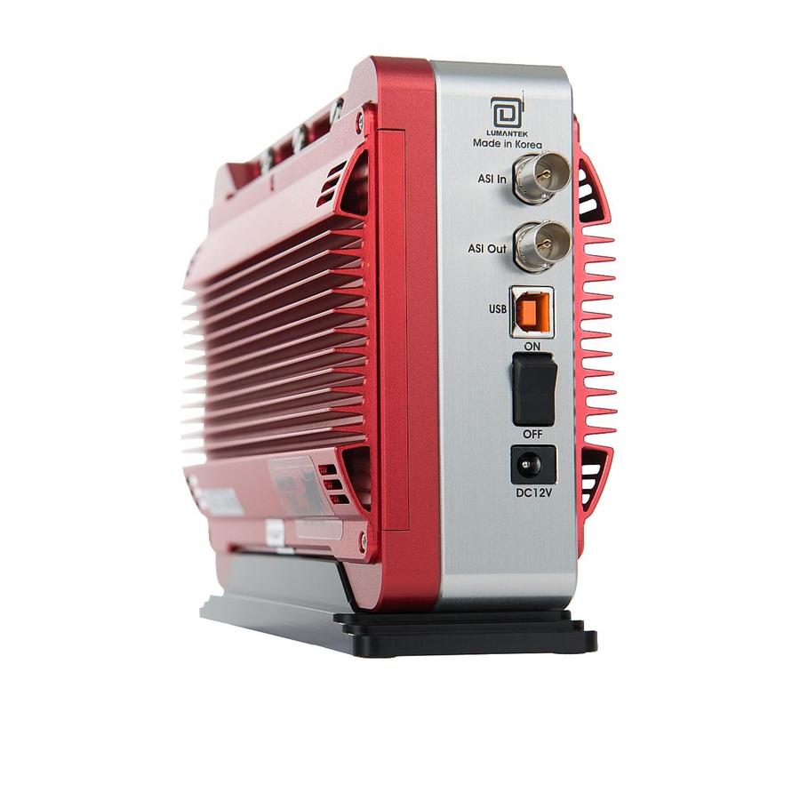
Page 9: Product Description
VENTUS 2.0 / Operational Manual VENTUS 2.0 Manual / Updated 2013/2/15 VENTUS 2.0 / Product Description 2.1 / Product Views and Dimensions 200 mm 140 mm FRONT Perspective 70 mm Right Side Panels Interface RF Output - USB LED: (On) when connected USB... -
Page 10: Package Contents
VENTUS 2.0 / Operational Manual VENTUS 2.0 Manual / Updated 2013/2/15 2.2 / VENTUS 2.0 Package Contents VENTUS Portable Case VENTUS 2.0 Body AC Power Adapter & AC Power Cord USB Flash Memory & Strap VENTUS Driver / T-pump /... -
Page 11: Hardware Install
VENTUS 2.0 / Operational Manual VENTUS 2.0 Manual / Updated 2013/2/15 VENTUS 2.0 / SYSTEM OPERATING 3.1 / VENTUS Hardware Install As explained in Chapter 2, after check- ing VENTUS components, the user can use it after just connecting power and... -
Page 12: Driver Install
VENTUS 2.0 / Operational Manual VENTUS 2.0 Manual / Updated 2013/2/15 3.3 / VENTUS Driver Installation Upon connecting the VENTUS for the first time, “Found New Hardware Wizard” window will pop up. Check “No, not this time”, then click “Next”. - Page 13 VENTUS 2.0 / Operational Manual VENTUS 2.0 Manual / Updated 2013/2/15 Click [Browse] and go to the file location. It’s placed at [..\VENTUS\Driver.install] in supplied USB Flash Memory. Choose the one folder between Window OS 32bit and 64 bit. Continue installing.
-
Page 14: Multi Driver Installation
VENTUS 2.0 / Operational Manual VENTUS 2.0 Manual / Updated 2013/2/15 3.4 / VENTUS Multi Driver Installation In case you need to operate more than 2 VENTUS on one computer, you must use different drivers for operating. Other USB. USB device has 2 type of VID(Vendor ID) and PID(Product ID). However, you may use separated drive for instance. - Page 15 VENTUS 2.0 / Operational Manual VENTUS 2.0 Manual / Updated 2013/2/15 Windows will recognize it as a new hardware component and open the “Found New Hardware Wizard”. Click on ‘No, not this time’ , then Click ‘Next’ . Check ‘Install from a list or specific location (Advanced)’ . Then click ‘Next’ .
- Page 16 VENTUS 2.0 / Operational Manual VENTUS 2.0 Manual / Updated 2013/2/15 Select ‘Search for best driver in these locations’ . Then, Click ‘Browse’ Navigate to the correct installation search path and assign the Driver path which doesn’t use before.4. Assign the driver except the existing ports.
- Page 17 VENTUS 2.0 / Operational Manual VENTUS 2.0 Manual / Updated 2013/2/15 The Wizard shows that the installation has been completed. Expand the USB DTV Singal Generator Driver in the Windows Device Manager (Control Panel > System > select Hardware tab> click on Device Manager).
-
Page 18: T-Pump Install
VENTUS 2.0 / Operational Manual VENTUS 2.0 Manual / Updated 2013/2/15 3.5 / VENTUS T-pump Install After completing the installation of VENTUS device driver, install T-pump software, which is provided for the operation of VENTUS, in the PC or notebook. T-pump is a program that controls all VENTUS interfaces. It controls recording, RF transmission, ASI transmission, and DTV selection functions. - Page 19 VENTUS 2.0 / Operational Manual VENTUS 2.0 Manual / Updated 2013/2/15 Continue T-pump installing. The T-pump installation has been completed. T-pump Program location : [ C:\Program Files\(C)LUMANTEK\T-Pump ]...
-
Page 20: T-Pump Operation
VENTUS 2.0 / Operational Manual VENTUS 2.0 Manual / Updated 2013/2/15 VENTUS 2.0 / T-PUMP OPERATION After completing the installation of VENTUS device driver and T-pump software, test DTV signal transmission, and capturing and transmission using ASI input/out using the T-pump software. - Page 21 VENTUS 2.0 / Operational Manual VENTUS 2.0 Manual / Updated 2013/2/15 T-pump UI Overview Items Description ASI-IN, OUT, DVB-T/H etc. Display selected Interface RF-OUT DTV Option-> When this option is selected, the interface will change TS-IN / OUT Select ASI INPUT, OUTPUT Port...
-
Page 22: Ts-In Option : Asi Input
VENTUS 2.0 / Operational Manual VENTUS 2.0 Manual / Updated 2013/2/15 4.1 / TS-IN Option : ASI Input 1. ASI Input is for input real time stream from other ASI Output Port. 2. First, run T-pump application. -> Then on your left side menu, click TS-IN. -> On Top Left Menu will change to ASI-IN signal. - Page 23 VENTUS 2.0 / Operational Manual VENTUS 2.0 Manual / Updated 2013/2/15 4. Click Rec button under RECORDER tab. Detail View of RECODER tab - ASI Loop Back - ASI Loop Back - ASI Loop Back 5. When you want to transmit ASI Input Signal as RF, go to [ASI->RF] tab. Then you can Select RF-OUT Modulation.
-
Page 24: Ts-Out Option : Asi Out Put
VENTUS 2.0 / Operational Manual VENTUS 2.0 Manual / Updated 2013/2/15 4.2 / TS-OUT Option : ASI Output 1. ASI Output is for transmitting the saved file [*.trp, *.tp] through ASI Output Port. 2. Top Left Menu in T-pump will change ASI-OUT when select TS-OUT option. - Page 25 VENTUS 2.0 / Operational Manual VENTUS 2.0 Manual / Updated 2013/2/15 2. Select Modulation Option in RF-OUT menu, then CW option will active. 3. Select Modulation Option in RF->OUT menu, then CW option will active. 4. Move from [PLAY] to [ASI->RF] tab, then click play button. It will transmit as CW.
-
Page 26: Rf Output Option : Dvb-T/H(2, 8K)
VENTUS 2.0 / Operational Manual VENTUS 2.0 Manual / Updated 2013/2/15 4.4 / RF Output option : CW Operation 1. To use CW mode, first you have to check CW under ASI-OUT. It is NOT able to checking CW option under RF-OUT. - Page 27 VENTUS 2.0 / Operational Manual VENTUS 2.0 Manual / Updated 2013/2/15 2. Select DVB-T option, Click file open button( ) and select [*.trp or *.tp] to do RF Output test. 3. Once you’ve selected a file, you can set RF Parameter as you need.
- Page 28 A sample *.dat file will give Frequency Table information. Create a sample file and save in [C:\Program Files\(C) LUMANTEK\T-pump\FreqTable] folder. Now you can search on the frequency table window if you save it at. 6. When you use AMP & Attenuator, you must click [ON] on the amplitude window.
-
Page 29: Rf Output Option : Dvb-T/H(4K)
VENTUS 2.0 / Operational Manual VENTUS 2.0 Manual / Updated 2013/2/15 4.6 / RF Output Option : DVB-T/H(4K) 1. When you select DVB-T/H(4K), DVB-T/H will appear on display window. 2. Click [SETTING] button and set like below image. - Inner Interleaver [S27] : 0 (Native Interleaver) - Page 30 VENTUS 2.0 / Operational Manual VENTUS 2.0 Manual / Updated 2013/2/15 3. T-pump Ver 2.2.0 updated as you could check NIT information. Click [From File] in[BIT/ SYMBOL RATE] box, then check the information of an opened *.ts file like below images. Click [Apply], automatically set all the options.
-
Page 31: Rf Output Option : Dvb-C
VENTUS 2.0 / Operational Manual VENTUS 2.0 Manual / Updated 2013/2/15 4.7 / RF Output Option : DVB-C 1. Top Left Menu in T-pump will change DVB-C when select DVB-C option. • DVB-C Parameter Value Items Value Const. Type 16 QAM... - Page 32 VENTUS 2.0 / Operational Manual VENTUS 2.0 Manual / Updated 2013/2/15 3. Set Const. Type under RF sub menu. 4. DVB-C needs to set Symbol Rate. You can input symbol rate by keybord input. Input Symbol Rate Value 5. After setting symbol rate, rest processing is same as DVB-T mode.
-
Page 33: Rf Output Option : Dvb-S
VENTUS 2.0 / Operational Manual VENTUS 2.0 Manual / Updated 2013/2/15 4.8 / RF Output Option : DVB-S 1. Top Left Menu in T-pump will change as DVB-S when select DVB-S option. *DVB-S2 Parameter Value Items Value Code Rate QPSK : 1/2, 2/3, 3/4, 5/6, 7/8 Const. - Page 34 VENTUS 2.0 / Operational Manual VENTUS 2.0 Manual / Updated 2013/2/15 4.9 / RF Output Option : DVB-S2 1. Top Left Menu in T-pump will change as DVB-S2 when select DVB-S2 option. *DVB-S2 Parameter Value Items Value Code Rate QPSK : 1/4, 1/3, 2/5, 1/2, 3/5, 2/3, 3/4, 4/5,...
- Page 35 VENTUS 2.0 / Operational Manual VENTUS 2.0 Manual / Updated 2013/2/15 * Guard Interval * IFFT Mode * Symbol Rate 4.10 / RF Output Option : DVB-T2 1. Top Left Menu in T-pump will change as DVB-T2 when select DVB-T2 option.
- Page 36 VENTUS 2.0 / Operational Manual VENTUS 2.0 Manual / Updated 2013/2/15 - The bandwidth of the channel - 1.7MHz, 5MHz, 6MHz, 7MHz, 8MHz, or 10MHz - FFT size in the channel - 1K, 2K, 4K, 8K, 16K, or 32K - Guard Interval...
- Page 37 VENTUS 2.0 / Operational Manual VENTUS 2.0 Manual / Updated 2013/2/15 Pilot Pattern PP1, PP2, PP3, PP4, PP5, PP6, PP7, or PP8 Version DVB-T2 version v.1.1.1 BwtExt Bandwidth Extension Normal carrier mode, or Extended carrier mode L1 repetition L1 repetition flag...
- Page 38 VENTUS 2.0 / Operational Manual VENTUS 2.0 Manual / Updated 2013/2/15 Total cells - The total number of OFDM cells per T2 frame. L1 size - The number of L1 signalling cells in a T2 frame Max Data cells - The maximum number of data cells excluding L1 signalling cells...
-
Page 39: Rf Output Option : Dab+/Dmb+Mux
VENTUS 2.0 / Operational Manual VENTUS 2.0 Manual / Updated 2013/2/15 4.11 / RF Output Option : DAB+/DMB+MUX Modulator Only 1. Upper left menu in the T-pump will be changed T-DMB when T-DMB option is selected. 2. Select T-DMB option, then click file open button [ ] and select [*.eti] to do... -
Page 40: Player Tab
VENTUS 2.0 / Operational Manual VENTUS 2.0 Manual / Updated 2013/2/15 3. Click ‘SETTING’ button if you need TII(Transmitter Identification Information) control. 4. This RF Output option doesn’t need to RF setting. Simply open stream file and set frequency and then play under PLAYER tab. - Page 41 VENTUS 2.0 / Operational Manual VENTUS 2.0 Manual / Updated 2013/2/15 Multiplexer + Modulator 1. Upper Left Menu in the T-pump will be changed T-DMB when T-DMB option is selected. 2. Choose multiplex mode or non-multiplex mode Select ‘setting’ button for choosing between multiplex mode and non-multiplex mode.
- Page 42 VENTUS 2.0 / Operational Manual VENTUS 2.0 Manual / Updated 2013/2/15 3. File Manage Window Click ‘File’ Button for adding files.ETI file(*.eti), MP1L2 file(*.mp2) supported. 4. Edit Window Select ‘Edit’ button for editing configurations.
- Page 43 VENTUS 2.0 / Operational Manual VENTUS 2.0 Manual / Updated 2013/2/15...
- Page 44 VENTUS 2.0 / Operational Manual VENTUS 2.0 Manual / Updated 2013/2/15 4-1. Click DAB mode ‘edit’ button for dab mode change. 4-2 Click ensemble ‘edit’ button for ensemble edit. 4-3 Load service edit window for service edit.
- Page 45 VENTUS 2.0 / Operational Manual VENTUS 2.0 Manual / Updated 2013/2/15 4-4 Load component edit window for component edit. 4-5 Load sub-ch edit window for sub-channel edit. 5. TII Window Select TII Button for edit TII information.
- Page 46 VENTUS 2.0 / Operational Manual VENTUS 2.0 Manual / Updated 2013/2/15 6. Project save and load Select save/load button for project save/load to/from file. 7. Set frequency in the Output panel then start transmitting it as RF. In the case of using AMP & Attenuator, you can adjust power level in the Amplitude menu.
-
Page 47: Rf Output Option : Opencable
VENTUS 2.0 / Operational Manual VENTUS 2.0 Manual / Updated 2013/2/15 4.12 / RF Output Option : OpenCable 1. Top Left Menu in T-pump will change QAM-B when select OpenCable option. * OpenCable Parameter Value Items Value Const. Type 64 QAM... - Page 48 VENTUS 2.0 / Operational Manual VENTUS 2.0 Manual / Updated 2013/2/15 3. After selecting the file, you need to set value among 64QAM, 256QAM and CW/I/J under RF sub menu. 4. Set frequency in the Output panel then start transmit it as RF. In the case of using AMP & Attenuator, you can adjust power level in the Amplitude menu.
-
Page 49: Rf Output Option : Atsc
VENTUS 2.0 / Operational Manual VENTUS 2.0 Manual / Updated 2013/2/15 4.13 / RF Output Option : ATSC 1. Top Left Menu in T-pump will change as ATSC when select ATSC option. * ATSC Parameter Value Items Value Const. Type 8VSB 2. - Page 50 VENTUS 2.0 / Operational Manual VENTUS 2.0 Manual / Updated 2013/2/15 3. This RF Output option can set only 8VSB. Simply open stream file and set frequency and then play under PLAYER tab. 4. Set frequency in the Output panel then start transmit it as RF. In the case of using AMP & Attenuator, you can adjust power level in the Amplitude menu.
-
Page 51: Rf Output Option : Isdb-T/Tb
VENTUS 2.0 / Operational Manual VENTUS 2.0 Manual / Updated 2013/2/15 4.14 / RF Output Option : ISDB-T/Tb 1. Top Left Menu in T-pump will change as ISDB-T /B when select ISDB-T/B option. * ISDB-T/Tb Parameter Value Items Value Code Rate 1/2, 2/3, 3/4, 5/6, 7/8 Const. - Page 52 VENTUS 2.0 / Operational Manual VENTUS 2.0 Manual / Updated 2013/2/15 3. Select ISDB-T option, Click file open button( ) and select *.trp or *.tp to do RF Output. 4. Set frequency in the Output panel then start transmit it as RF. In the case of using AMP & Attenuator, you can adjust power level in the Amplitude menu.
-
Page 53: Rf Output Option : Cmmb
VENTUS 2.0 / Operational Manual VENTUS 2.0 Manual / Updated 2013/2/15 4.15 / RF Output Option : CMMB 1. Top Left Menu in T-pump will change as CMMB when select CMMB option. *CMMB Parameter Value Items Value Constellation BPSK, QPSK, 16QAM Reed Solomon 240.240... - Page 54 VENTUS 2.0 / Operational Manual VENTUS 2.0 Manual / Updated 2013/2/15 Data Form Sign CAS Stream Sign CMMB Channel Information Stream Information Status Sign CMMB UI can intuitively check the each of the stream channel information for the file MFID, type of service, Time Slot, the file size, codec information, and transmission status.
- Page 55 VENTUS 2.0 / Operational Manual VENTUS 2.0 Manual / Updated 2013/2/15 Constellation Modulation Method : BPSK, QPSK, 16QAM B etween each frame can be set up independently, but the frame with MF_ ID 0 is set up with BPSK. Constellation is relate to the amount of data that can carry the load (bps), 16 QAM is 2 times of QPSK, and 2 times of BPSK.
- Page 56 VENTUS 2.0 / Operational Manual VENTUS 2.0 Manual / Updated 2013/2/15 Once made 240,240 higher the out bit rate, When the data capacity reduced replace in QPSK BPSK can not fill yet still receive the red line. LDPC LDPC is error-correction techniques in the CMMB Method. B etween each frams, any values can be set, but 0 in the CLCH MF_ID is transmite 1 / 2.
- Page 57 VENTUS 2.0 / Operational Manual VENTUS 2.0 Manual / Updated 2013/2/15 Once made 240,240 higher the out bit rate, When the data capacity reduced replace in QPSK BPSK can not fill yet still receive the red line. Time Slot CMMB is transfer 1 divided by 40 seconds unit. This unit is called Time Slot.
- Page 58 VENTUS 2.0 / Operational Manual VENTUS 2.0 Manual / Updated 2013/2/15 It tells about the list of the number of time slot. However, as it says, the value can not be the same as always. When selecting 6 from the list, out rate has been higher than Source rate, the setting is not properly operate.
- Page 59 VENTUS 2.0 / Operational Manual VENTUS 2.0 Manual / Updated 2013/2/15 One channel stream file open button, select Open, then again, you receive the following pop-up menu. --> When adding Channel: (Yes), When reset the Chennel: (NO) In 3.1.0 Version, if the CLCH’s channel information and the actual multi mfs. stream does not match with service number, then the pop up window will show as below.
- Page 60 VENTUS 2.0 / Operational Manual VENTUS 2.0 Manual / Updated 2013/2/15 Change set 16 QAM to BSPSK in Constellation section, Alarm ( Red-Bar ) is appeared, due to Bitrates Error. Then mean User’s source (file) bitrates Is bigger than output bitrates, and need to be resetting.
- Page 61 VENTUS 2.0 / Operational Manual VENTUS 2.0 Manual / Updated 2013/2/15 Then now, source bitrates is equal or less then output bitrates, then decoding is properly working.
- Page 62 VENTUS 2.0 / Operational Manual VENTUS 2.0 Manual / Updated 2013/2/15 1. Full CMMB U-Band Frequency table on T-PUMP 2. Correct Wrong Audio Codec info 3. When User open up MRF file, which has out of CMMB standard at CLCH, and pops up right standard CLCH MFS parameter for Comparing, automatically, and give Selection to user as below picture.
- Page 63 VENTUS 2.0 / Operational Manual VENTUS 2.0 Manual / Updated 2013/2/15 1. Enable to open, and play out with MFS which has no padding data ( Both of S-MFS/M-MFS ) 2. Enable to insert S-MFS which has no Padding data for multiplexing 3.
- Page 64 VENTUS 2.0 / Operational Manual VENTUS 2.0 Manual / Updated 2013/2/15 4.16 / ATSC-M/H / Introduction of M/H Multiplexer Part in VENTUS 1.0 Block Diagram of M/H Multiplexer in VENTUS 1.0 Main TS Processor - automatically controls main TS packet about timing & PCR adjustment.
- Page 65 VENTUS 2.0 / Operational Manual VENTUS 2.0 Manual / Updated 2013/2/15 Concept of M/H Multiplexer in VENTUS 1.0 Ability, Just exact simulate condition like ATSC Mobile DTV on US. Air Through editing Ensemble configuration with editing Parade configuration and choosing Parades,User enable to generate a Signal form without any limitation for broadcasting in ATSC-Mobile DTV standards specification GUI Procedure -Setting Ensembles ->...
- Page 66 VENTUS 2.0 / Operational Manual VENTUS 2.0 Manual / Updated 2013/2/15 Ensemble GUI - Feature Support Input file Single service stream (IP Packet based) - Service Mode Multiplexed ensemble stream (IP Packet based) - Ensemble mode Support Editing Editing of the service ID, service Name, destination IP address from each service is supported.
- Page 67 VENTUS 2.0 / Operational Manual VENTUS 2.0 Manual / Updated 2013/2/15 Ensemble GUI – Feature on Each Area (1) Selection Area of Ensemble Set No. - Ensemble Status View Area, Service View Area and SSC View Area about selected Ensemble set No. is loaded.
- Page 68 VENTUS 2.0 / Operational Manual VENTUS 2.0 Manual / Updated 2013/2/15 Edit Ensemble GUI - Example (1): File Input IP stream file : In this area, right-click your mouse and select Insert. TS stream file : Click the appropriate button.
- Page 69 VENTUS 2.0 / Operational Manual VENTUS 2.0 Manual / Updated 2013/2/15 Edit Ensemble GUI- Example (2): Service ID, Service Name, IP Address Edit Service ID click left mouse on Service ID area and modify the value Edit Service Name click left mouse on Service Name area and modify the name Edit Service IP Addr.
- Page 70 VENTUS 2.0 / Operational Manual VENTUS 2.0 Manual / Updated 2013/2/15 Edit Ensemble GUI - Example (3): Add Component Descriptor in Service Mode Select Service in SMT Service to edit Select Component to edit Select Component Level Descriptor in component...
- Page 71 VENTUS 2.0 / Operational Manual VENTUS 2.0 Manual / Updated 2013/2/15 Parade GUI in T-Pump GUI Parade GUI - Feature(1) Parade Set Support - Support to select Parade ID, NoG, TPC PRC, RS Frame Mode, SCCC Block Mode, Primary & Secondary RS Code Mode, and Select Ensemble.
- Page 72 VENTUS 2.0 / Operational Manual VENTUS 2.0 Manual / Updated 2013/2/15 Parade GUI – Area Summary Bit-rate View Area Parade Edit View Area Slot Status View Area Parade Usage View Area Parade GUI – Feature on Each Area (1) Parade Usage View area - Loads Parade Edit View area depending on the selected Parade number.
- Page 73 VENTUS 2.0 / Operational Manual VENTUS 2.0 Manual / Updated 2013/2/15 Parade GUI – Feature on Each Area (2) Parade Edit View area - Parade Edit View area is for the setting zone. If RS-frame Ensemble is not selected, Parade cannot be activated for RF output.
- Page 74 VENTUS 2.0 / Operational Manual VENTUS 2.0 Manual / Updated 2013/2/15 Edit Parade GUI - Example (2): Determine Parade whether to use for RF Output or not Edit Parade GUI - Example (2): Determine Parade whether to use for RF Output or not...
- Page 75 VENTUS 2.0 / Operational Manual VENTUS 2.0 Manual / Updated 2013/2/15 Edit Parade GUI - Example (3): Change According to RS Frame Mode RS Frame Mode : Single Frame : Primary RS Frame zone is activated. RS Frame Mode : Dual Frame...
- Page 76 VENTUS 2.0 / Operational Manual VENTUS 2.0 Manual / Updated 2013/2/15 Edit Parade GUI - Example (4): Change According to the SCCC Block Mode SCCC Block Mode : Separate Block : The Region set is separated to Region A~D SCCC Block Mode : Paired...
- Page 77 VENTUS 2.0 / Operational Manual VENTUS 2.0 Manual / Updated 2013/2/15 ATSC-M/H : Appendix : User Friendly GUI Example For User Centric Mind User Friendly GUI Example (1) Set Ensemble Set Parade Select Output Start RF Output Parade 1. Open file (Required) 2.
- Page 78 VENTUS 2.0 / Operational Manual VENTUS 2.0 Manual / Updated 2013/2/15 User Friendly GUI Example (2) Set Ensemble Set Parade Select Output Start RF Output Parade 1. Link Ensemble (Required) 2. Setting Parade ID, NOG, PRC, RS Frame Mode, SCCC Block Mode (Optional)
- Page 79 VENTUS 2.0 / Operational Manual VENTUS 2.0 Manual / Updated 2013/2/15 User Friendly GUI Example (3) Set Ensemble Set Parade Select Output Start RF Output Parade 1. Select Output Parade (Required)
- Page 80 VENTUS 2.0 / Operational Manual VENTUS 2.0 Manual / Updated 2013/2/15 User Friendly GUI Example (4) Set Ensemble Set Parade Select Output Start RF Output Parade 1. Set the center frequency 2. Set AWGN(option) and Set Amplitude(option) 3. With the Play/STOP button, User can select RF output start/stop...
-
Page 81: Auto Test
VENTUS 2.0 / Operational Manual VENTUS 2.0 Manual / Updated 2013/2/15 4.17 / AUTO TEST - Automated test menu is applied on over T-PUMP Version 2.7. - Regardless of Modulation option, When you select an Modulation and the Auto-Test, then the Auto option is available to the test. - Page 82 VENTUS 2.0 / Operational Manual VENTUS 2.0 Manual / Updated 2013/2/15 Channel Test - When testing to specify the frequency range at regular intervals channel scan. From the main menu when you select Auto-Test Automation Test is a pop-up menu.
- Page 83 VENTUS 2.0 / Operational Manual VENTUS 2.0 Manual / Updated 2013/2/15 On Level entry, select the specified time to test and exit points then Specifies the interval, and the cycle. -> Start, Stop entry, Step items, Duration, select the item you will receive the following example.
- Page 84 VENTUS 2.0 / Operational Manual VENTUS 2.0 Manual / Updated 2013/2/15 Level Test - To test at regular intervals by specifying a range of Level Power Level test case. From the main menu when you select Auto-Test Automation Test is a pop-up menu.
- Page 85 VENTUS 2.0 / Operational Manual VENTUS 2.0 Manual / Updated 2013/2/15 On Level entry, select the specified time to test and exit points then Specifies the interval, and the cycle. -> Start, Stop entry, Step items, Duration, select the item you will receive the following example.
- Page 86 VENTUS 2.0 / Operational Manual VENTUS 2.0 Manual / Updated 2013/2/15 Channel / Level Test - When testing the channel and level in both time. From the main menu when you select Auto-Test Automation Test is a pop-up menu. In Channel/Level Test Tab menu, After you specify the start and end step, specify the frequency.
- Page 87 VENTUS 2.0 / Operational Manual VENTUS 2.0 Manual / Updated 2013/2/15 On Level entry, select the specified time to test and exit points then Specifies the interval, and the cycle. -> Start, Stop entry, Step items, Duration, select the item you will receive the following example.
-
Page 88: Awgn (Addictive White Gaussian Noise)
VENTUS 2.0 / Operational Manual VENTUS 2.0 Manual / Updated 2013/2/15 4.18 / AWGN(Addictive White Gaussian Noise) White ? - Including All frequency spectrum. - White Light include red, green, yellow. - Flat Spectrum at frequency domain. Gaussian ? - Statistical distribution is Gaussian. - Page 89 VENTUS 2.0 / Operational Manual VENTUS 2.0 Manual / Updated 2013/2/15 AWGN simulation result (Histogram) Level1 Level2 Level3 AWGN Block diagram...
- Page 90 VENTUS 2.0 / Operational Manual VENTUS 2.0 Manual / Updated 2013/2/15 Feature - Noise Bandwidth = 2 x Signal BW. - Easy Setting. C/N : +60 ~ -30dB, 0.1dB step BW : Interesting signal BW, 0.1Mhz Step - Fully digital controlled.
- Page 91 VENTUS 2.0 / Operational Manual VENTUS 2.0 Manual / Updated 2013/2/15 CW Test RF level : 0dBm, C/N : 0dB, BW : 4MHz CW Example - Total Power : Constant (RF level = 0dBm) - C/N : 0dB : Signal Power is equal to Noise Power in 4Mhz BW - CW level(power and level is same at CW) : -3.4dBm = 0.457mW...
-
Page 92: Appendix. A Ventus User Menu Summary
VENTUS 2.0 / Operational Manual VENTUS 2.0 Manual / Updated 2013/2/15 Appendix. A Ventus User Menu Summary A.1 Ventus operating Procedure Connect VETNUS USB Connect VETNUS USB Connect VETNUS USB Connect VETNUS USB Connect VETNUS USB Connect VETNUS USB DVB-T Mode ASI-IN Mode 1. - Page 93 In this upgrade version, you can edit Frequency Table by yourself. The saved file placed C:\Program Files\(c)LUMANTEK\T-Pump\FreqTable.+ A sample *.dat file has frequency table information. If you save a sample file in [C:\Program Files\(c)LUMANTEK\T- Pump\FreqTable], you can search it in Freqeuncy Table Window.
-
Page 94: Appendix. B Ventus User Api (Vtsapi Calling Sequence)
VENTUS 2.0 / Operational Manual VENTUS 2.0 Manual / Updated 2013/2/15 Appendix. B Ventus User API (VtsAPI Calling Sequence) Calling Sequence VtsAPI_Initialize() CountDevice() OpenDevice() Pump control setting Modulator setting for DAB Modulator File setting for DAB Modulator RF setting DMA tranfer... - Page 95 VENTUS 2.0 / Operational Manual VENTUS 2.0 Manual / Updated 2013/2/15 Modulator setting ModulatorInit(VTS_BroadcastType_t t_BcType) => Modulator H/W image download ex) DAB : ModulatorInit(11/*VTS_BC_T_DMB*/) B.4 File setting for DAB Modulator T_DMB_Parse (unsigned char* u1p_Buff, unsigned int u4_Size, bool b_IsDSLFormat) => *.eti or *.dsl . part of *.eti or *.dsl passing and then DAB configure parameter ex) *.eti...
- Page 96 B.6 DMA transfer PumpGetHwBuffUsed(unsigned int* u4p_HwBuffUsed, unsigned int* u4p_RxBuffUsed) => H/W Buffer usage check ex) PumpGetHwBuffUsed(&gu4_BuffUsed, NULL) PumpGetHwBuffSize(&gu4_BuffSize) => H/W Buffer Total Size bring . (Ventus 1.0은 8MBytes, Ventus 2.0은 16MBytes) PumpWrite( unsigned char* u1p_Buff, unsigned int u4_dwWrite, unsigned long* u4p_TransferedBytes, bool b_IsDSLFormatForDABModulator) =>...
- Page 97 VENTUS 2.0 / Operational Manual VENTUS 2.0 Manual / Updated 2013/2/15 all sequence VtsAPI_Initialize(); CountDevice(); OpenDevice(0); PumpSetState(1);//Stop Clear PumpSetMode (6, 0, 0, 0); ModulatorInit(11);//for DAB Modulator Image Download ModulatorSetRF(400000000);//400MHz AttenSetFrequency(400000000);//400MHz AttenSetOutLevel(-200);//-20dBm T_DMB_Parse(u1_Buff, 24576, 0);//DAB Modulator parameter setting PumpSetState(2);//run Loop: PumpGetHwBuffUsed(&gu4_BuffUsed, NULL) // Total –...
- Page 99 11F, BYC-A, 371-17, Gasan-Dong, Gumcheon Gu, Seoul, Korea, (153-803) Tel: +82 2 6947 7400, Fax: +82 2 6947 7440 Printed in KOREA © Lumantek Co., Ltd. CopyRight 2013 WWW.LUMANTEK.COM...
Need help?
Do you have a question about the VENTUS 2.0 and is the answer not in the manual?
Questions and answers