Table of Contents
Advertisement
Advertisement
Table of Contents

Related Manuals for Daitsu DS-9KIDB


Summary of Contents for Daitsu DS-9KIDB
-
Page 1: Service Manual
Service Manual Models: ASD9U2I DN ASD912UI DN... - Page 2 Service Manual Model Product Code Rated Voltage 220-240 Power Rated Frequency supply Phases Cooling capacity(max~min) 5200(2140~4836) Heating capacity(max~min) 5400(2579~5510) Cooling Power Input(max~min) 1450 Heating Power Input(max~min) 1550 Cooling Current Input 6.88 Heating Current Input 6.43 Rated Power Input 1780 Rated Current 7.90 SEER SCOP...
- Page 3 Service Manual Cross-sectional Area of Power Cable Conductor Recommended Power Cable(Core) Connection Pipe Connection Method Flare Connection Flare Connection Not Additional Gas Connection Pipe Length Connection Pipe Gas Additional Charge Outer Diameter of Liquid Pipe(GREE Allocation) (Metric) Outer Diameter of Gas Pipe(GREE Allocation) (Metric) Outdoor Outer Diameter of Liquid Pipe(GREE Allocation)
- Page 4 550/500/430/300/- 550/480/410/290/- Cooling Capacity 2500 3200 Model Service Manual Service Manual Service Manual Service Manual Heating Capacity 2800 3400 550/500/430/300/- 550/480/410/290/- Model of Indoor Unit Model Model Model Model Cooling Capacity 2500 3200 Model of Indoor Unit Heating Capacity 2800 3400 550/500/430/300/- 550/480/410/290/-...
-
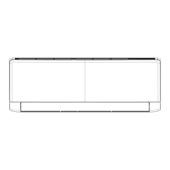
Page 5: Outline Dimension Diagram
Service Manual Outline Dimension Diagram Indoor Unit Φ55 Φ55 Unit:mm Models 09/12K Technical Information... - Page 6 Service Manual Service Manual 3. Outline Dimension Diagram 3. Outline Dimension Diagram Unit:mm Technical Information Unit:mm Unit:mm Technical Information Technical Information...
-
Page 7: Function And Control
Service Manual Function and Control Remote Controller Introduction Buttons on Remote Controller On/Off button Mode button Fan button ▲/ button Swing button Sleep button Temp button Turbo button I Feel button Timer button X-Fan button Light button Icon Display on Remote Controller Temp. - Page 8 Service Manual 1. ON/OFF button Press this button to turn on the unit. Press this button again to turn off the unit. 2. MODE button Each time you press this button,a mode is selected in a sequence that goes from AUTO, COOL, DRY, FAN, and HEAT *, as the following: * Note: Only for models with heating function.
- Page 9 Service Manual TEMP button Press this button, you can see indoor set temperature, indoor ambient temperature on indoor unit’s display. The setting on remote controller is selected circularly as below: no display TURBO button Press this button to activate / deactivate the Turbo function. 9.
-
Page 10: Replacement Of Batteries In Remote Controller
Service Manual WIFI Function Press this button to turn on the unit. Press this button again to turn off the unit. Press "MODE" and "TURBO" button simultaneously to turn on or turn off WIFI function. When WIFI function is turned on, the " "... -
Page 11: Notes For Installation And Maintenance
Service Manual Part : Installation and Maintenance Notes for Installation and Maintenance Safety Precautions: 10. If the power cord or connection wire is not long enough, please get the specialized power cord or connection wire Important! from the manufacture or distributor. Prohibit prolong the wire by yourself. -
Page 12: Main Tools For Installation And Maintenance
Service Manual Main Tools for Installation and Maintenance 1. Level meter, measuring tape 2. Screw driver 3. Impact drill, drill head, electric drill 4. Electroprobe 5. Universal meter 6. Torque wrench, open-end wrench, inner hexagon spanner 7. Electronic leakage detector 8. -
Page 13: Installation Procedures
Service Manual Installation Manual Installation procedures Start installation Preparation before installation Read the requirements select installation Prepare tools for electric connection location Select indoor unit Select outdoor unit installation location installation location Install the support of outdoor unit Install wall-mounting (select it according to the actual situation) frame, drill wall holes Connect pipes of indoor... - Page 14 Space to the wall Space to the wall Space to the wall At least 15cm At least 15cm At least 15cm At least 15cm At least 15cm At least 15cm Space to the wall Space to the wall Space to the wall...
-
Page 15: Installation Parts-Checking
Service Manual Installation Parts-Checking Requirements for electric connection 1. Safety Precaution Name Name Wrapping tape Connection pipe Drainage pipe frame Connecting conditioner. cable(power cord) remote controller Wall pipe Note: Selection of Installation Location 1. Basic Requirement: 2. Grounding Requirement: 2. Indoor Unit: accessible. - Page 16 Service Manual 5. Connect the Pipe of Indoor Unit 3. Install Wall-mounting Frame Wall Wall Mark in the middle of it Level meter Space Space to the to the Open-end wall wall wrench above above 150mm 150mm Union nut Pipe Pipe joint Union nut Pipe...
- Page 17 Service Manual 7. Connect Wire of Indoor Unit 8. Bind up Pipe Panel Screw Wiring cover Indoor and outdoor power cord Indoor unit pipe Cable-cross Liquid hole pipe Band Drain hose Power connection wire Drain hose Connection pipe Band Indoor power cord N(1) Note: yellow-...
-
Page 18: Electrical Connections
Service Manual Electrical Connections Handle 1. Remove the handle at the right side plate of the outdoor unit (one screw). 2. Remove the cable clamp, connect the power connection cable with the terminal at the row of connection and fix the Front the indoor unit. -
Page 19: Installing The Outdoor Unit
Service Manual Installing the Outdoor Unit Use bolts to secure the unit to a flat, solid floor. Install the drain fitting and the drain hose(for When mounting the unit on a wall or the roof, make heat pump only) model with heat pump only) Do not install the outdoor unit in pits or air vents sure the support is firmly secured so that it cannot Condensation is produced and flows from the outdoor unit... -
Page 20: Installation Dimension Diagram
Service Manual Installation Dimension Diagram Use suitable instruments for the refrigerant R410A. Do not use mineral oils to clean the unit. Contact service center before installation to avoid the malfunction due to unprofessional installation. Ensure that the recommende dspace is left around the appliance. 18/21K 24/28K 50cm...
Need help?
Do you have a question about the DS-9KIDB and is the answer not in the manual?
Questions and answers