
Related Manuals for Honeywell RAEGuard 2 PID


Summary of Contents for Honeywell RAEGuard 2 PID
- Page 1 RAEGuard 2 PID ___________________________________ User Guide ___________________________________ P/N: H-D03-4001-000 Rev M February 2018...
-
Page 2: Table Of Contents
RAEGuard 2 PID User’s Guide Contents Section 1: RAEGuard 2 PID User’s Guide General Information ............6 General Specifications ............8 RAEGuard 2 PID Specifications ......8 Proper Product Disposal At End Of Life ....9 Operation ................10 Physical Description ............11 Physical Dimensions ............ - Page 3 RAEGuard 2 PID User’s Guide Language ................27 Set Span Value ..............27 Meas. Gas* ............... 27 Ext. Alarm Delay* ............27 Pump Duty (%)* ............... 27 Calibration Type* ............. 27 Pump Cycle(s)* ..............27 Calibration Gas* ............... 27 Pump Status* ..............27 Bus Baudrate ..............
- Page 4 RAEGuard 2 PID User’s Guide 15.3 Instruction For Safe Use ........57 15.4 Use In Hazardous Areas ........58 15.5 Year of manufacture ..........58 15.6 Specifications ............59 General Information ........... 60 Grounding (Earth Connection) ........61 Physical Description ........... 62 Sensor Parts And Dimensions ........
- Page 5 In no event is Honeywell liable to anyone for any direct, special, or consequential damages. The information and specifications in this document are subject to change without notice.
-
Page 6: Section 1: Raeguard 2 Pid User's Guide
RAEGuard 2 PID User’s Guide Section 1: RAEGuard 2 PID User’s Guide... -
Page 7: General Information
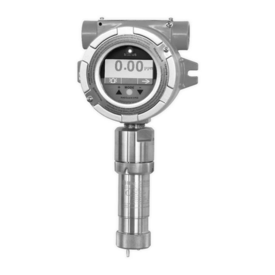
RAEGuard 2 PID has a graphic display and local sound alarm and light status indicator. A magnetic key interface enables the detector to be calibrated and operational parameters adjusted with the explosion- proof enclosure in place. - Page 8 RAEGuard 2 PID User’s Guide Applications: • Refineries, petrochemical and natural gas plants • Metallurgical • Chemical, medication • Environmental protection • Electricity, communications • Fire protection • Utilities • Pulp and paper, printing • Storage • Sewage disposal •...
-
Page 9: General Specifications
RAEGuard 2 PID User’s Guide General Specifications RAEGuard 2 PID Specifications Basic Parameters Principle PID (photoionization detector) Sensor Digital Smart Sensor Sampling Internal diaphragm pump Working Current DC 10 to 28V, 210mA at 24V Power <5W • 4-20mA • Three-level programmable alarm relays Output •... -
Page 10: Proper Product Disposal At End Of Life
RAEGuard 2 PID User’s Guide RAEGuard 2 PID Specifications (continued) Physical Parameters Dimensions, 257 x 201 x 107 mm L x W x H (10.1" x 7.9" x 4.2") Material Stainless steel Weight 3.5 kg (7.7 lbs) Certification ATEX II 2 (1) G Ex db [ia Ga] IIC T4 Gb UL/CSA Class I, Div. -
Page 11: Operation
Prior to factory shipment, the RAEGuard 2 PID is calibrated and tested. However, the user should calibrate the instrument before the first use. -
Page 12: Physical Description
RAEGuard 2 PID User’s Guide Physical Description The RAEGuard 2 PID can be easily installed and integrated with various control systems. It is designed with flexible pipe- holding/wall-mounting options and standard connection terminals. Physical Dimensions The physical dimensions are as shown: 107mm (4.2") -
Page 13: Installation And Access Instructions
First, decide where the transmitter will be mounted. (Refer to installation drawing, below.) Drill two holes in mounting surface, with the center of the holes 5.25" (133mm) apart. Besides directly mounting the RAEGuard 2 PID to a wall, it can be mounted on a pipe. - Page 14 Note: When installing the RAEGuard 2 PID, make sure the sensor is vertically oriented (pointing straight down). Also, make sure the water-trap filter is connected to the gas inlet labeled “IN” (the longer of the two inlets). Note: Only operate the RAEGuard 2 PID in a non- condensing environment. Wall...
-
Page 15: Instrument Disassembly
RAEGuard 2 PID User’s Guide Instrument Disassembly Prior to service: Make sure power is OFF. Observe all Hazardous Location Safety procedures. 1. Loosen the fastening bolt 3. Tilt the instrument assembly before unscrewing the 90˚. housing lid. Unscrew the 4. Unlock the 24-pin connector housing lid from the housing on the ribbon cable. -
Page 16: Electrical Wiring
RAEGuard 2 PID User’s Guide To reassemble the instrument: Reconnect the 24-pin connector of the ribbon cable and lock it in place. Fasten the cable to the board. Mate the board with the clip on the left side and tilt it over. -
Page 17: Wiring Procedure
PC boards. Note: The terminal block plugs accept 12 AWG to 24 AWG wire. Lace the wires through the RAEGuard 2 PID’s wire hole(s) and connect wires to the corresponding pin numbers of the terminal... -
Page 18: Earth Grounding Instructions
RAEGuard 2 PID User’s Guide Earth Grounding Instructions 6.5.1 External Earth Grounding Fasten the crimped ground wire with hardware as illustrated below. The wire should have a minimum cross-section area of 4mm for its conductor. M4 Screw M4 Split washer... -
Page 19: Finished Grounding Wires
RAEGuard 2 PID User’s Guide 6.5.3 Finished Grounding Wires Internal and external grounding are shown here, as well as an alternate external grounding point. Always follow local electrical guidelines. Alternate External earth earth grounding grounding point Internal earth grounding Alarm Contact Setup The alarm contacts can drive external alarms such as a light or buzzer. - Page 20 Note: The relays may be disabled based on the sensor that is attached to the RAEGuard 2 PID. Certain sensors, such as the 1-1000 ppm DigiPID, disable the correction factor library and relays of the RAEGuard 2 unit. Users who require these functions should use the...
-
Page 21: Display And User Interface
RAEGuard 2 PID User’s Guide Display And User Interface User Interface The RAEGuard 2 PID’s user interface consists of a status LED, an LCD display, and three keys, [+], [MODE], and [-]. The three keys are operated by using the Magnet Key. -
Page 22: Using The Magnet Key
Using the magnet end of the Magnet Key, briefly touch the glass above the MODE circle or the triangles labeled [+] and [-]. Then remove the key straight out and away from the RAEGuard 2 PID. RAEGuard Magnet Key touching glass above the [+] triangle. -
Page 23: Instrument Status Display
RAEGuard 2 PID User’s Guide If there is an error, the “Fault” LED blinks and an error message blinks. Each alarm condition has a corresponding LED that blinks an amber color when the readings are outside a specified range or limit. -
Page 24: Navigating Settings
Thank you for reading this data sheet. For pricing or for further information, please contact us at our UK Office, using the details below. UK Office Keison Products, P.O. Box 2124, Chelmsford, Essex, CM1 3UP, England. Tel: +44 (0)330 088 0560 Fax: +44 (0)1245 808399 Email: sales@keison.co.uk...
Need help?
Do you have a question about the RAEGuard 2 PID and is the answer not in the manual?
Questions and answers