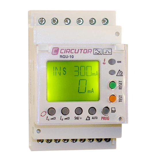
Circutor RGU-10 User Manual
Rgu-10 series electronic earth leakage protection relay
Hide thumbs
Also See for RGU-10:
- Instruction manual (46 pages) ,
- Quick start manual (4 pages) ,
- Quick start manual (4 pages)
Table of Contents
Advertisement
Advertisement
Table of Contents

Subscribe to Our Youtube Channel
Related Manuals for Circutor RGU-10


Summary of Contents for Circutor RGU-10
- Page 1 – – – – User manual Extended version M 982 032 01 / 03 / 06 A © CIRCUTOR, S.A.
-
Page 2: Table Of Contents
Checks on receipt. This manual assists in the installation and use of the RGU-10/RGU-10C earth leakage relay so that the best possible use can be gained from it. Please check the following points on receipt of the relay: • The equipment delivered matches your order specifications. - Page 3 DIN RAIL PANEL (ADAPTER ACCESSORY) SMALL 3 MODULE SIZE INSTANT CURRENT LEAKAGE DISPLAY BACKLIT PRE-ALARM LCD DISPLAY RELAY GREEN Normal operation SENSITIVITY from 50 to status. 80%I ∆N RED Trip status by fault or DELAY from 20 ms to 10 other event.
-
Page 4: General Features
GENERAL FEATURES The RGU-10 earth leakage relay is type A programmable electronic earth leakage protection equipment with two independent relays 4, the main output for checking the cut off device and performing the protection function and the pre-alarm relay for installation prevention and maintenance. - Page 5 Associated standard IEC 61008.1, IEC 38 Other features: 3 modules. DIN rail. In a panel using front accessory, code M5ZZF1 Displaying instant leakage values. Backlit LCD display. Built-in RS485 communications (Modbus RTU®). RGU-10C only Available models: RGU-10 SERIES CODE RGU-10 P11941 RGU-10C P11944 Page 5...
-
Page 6: Installation And Start-Up
INSTALLATION AND START-UP This manual contains information and warnings about the RGU-10/RGU-10C which must be followed to guarantee the proper operation of all instrument functions and to maintain it in a safe condition. The equipment must not be switched on until it is finally connected to the electrical board. - Page 7 External input for Trip/Rearm: - Terminals 1 – 2 - Type of input Optocoupled ± 20% / 0.7 W - Maximum voltage / Maximum power 110 – 230 V D. Earth leakage current measurement circuit Scale range Full scale Resolution display ±...
- Page 8 Connection diagram features The connection for the equipment using 0.5 mm diameter cable. Recommended tightening torque is 0.5-0.6 Nm. Length of cable to strip 5-7 mm. It is recommended that meshed cable is used to connect the toroid over large distances. Terminal list Terminal description Voltage input ON/OFF external L...
-
Page 9: Connection Diagram
CONNECTION DIAGRAMS RGU-10/RGU-10C connection with current emission coil. In the event of powering the equipment before the breaking device (AUTOMATIC SWITCH) in an earth leakage trip situation because of a fault, test or toroid error: Note the cause of the trip on the red display. - Page 10 RGU-10/RGU-10C connection with current emission coil. The following has to be taken into consideration in the event of powering equipment after the breaking device. The breaking device has to be a manually resettable device. After dripping, the equipment is disconnected losing all information on the reasons for the trip. The system is reset only by resetting the breaking device.
- Page 11 The equipment operates to its maximum whenever it is supplied from the installation itself before the breaking device or from an independent auxiliary power supply. However if the power supply from the installation is below the breaking device the system continues to be properly protected even though with limitations in terms of its disconnection performance through lack of power supply.
- Page 12 RGU-10/RGU-10C connection with undervoltage coil. Power supply to the equipment is before the breaking device. This breaking device may be an automatic switch or contactor. Using a CONTACTOR the protection is reset by pressing RESET, or by using an AUTOMATIC SWITCH. The breaking device must be rearmed beforehand.
- Page 13 Other equipment's power supply voltages: Power supply from 24 to 120 V Page 13...
- Page 14 CONNECTING THE EQUIPMENT IN POSITIVE SAFETY This installation mode provides the most conservative protection from the point of view of personal and property safety in electrical installations. With this type of equipment connection and setting, persons all goods are protected against faults where the earth relay leakage loses its protection capacity.
- Page 15 When this type of safety is used using the current emission coil, it can only be assured that the system will trip went the earth leakage relay is not operating correctly. The breaking device has the power to trip using the maximum current coil. (AUTOMATIC SWITCH). The equipment is set by programming by pressing the Std/+ key in positive safety mode.
-
Page 16: Description
DESCRIPTION The front of the equipment which is formed by the display, buttons and LEDs, is protected with a sealable plastic cover which has the appropriate holes to access the RESET, TEST and SETTING keys. Generic functions of the LEDs and front keypad: - GREEN LED: Equipment on - RED LED: Leakage trip - YELLOW LED: Pre-alarm... - Page 17 Accessible with cover raised. Keys with dual function. With a long press, the equipment is entered to set the values. With a short press, the option within a series of values defined in the equipment is selected. SENSIVITY button, I ∆...
-
Page 18: Operation
OPERATION When the equipment is powered at its rated voltage, the green LED on the front is on, the backlit LCD is green indicating the software and hardware version. After a short while, the version disappears and the default display values appear on the display. - Page 19 The RGU-10/ RG5-10C allow the display and setting of all required parameters to complete the earth leakage protection adjustment with pre-alarm and communications. PARAMETER UNIT Preset pre-alarm trip delay mS / S Sensitivity of pre-alarm in % I ∆ N + (contact 6-5 NA) / nothing (contact 6 - 5 NC) Pre-alarm relay contact status.
- Page 20 REMOTE TRIP. When a trip is forced (input terminals 1-2, by applying 230 V) the equipment is tripped and disabled and an "EXT" message is shown on the display in red and also the LED is on. It has to remain permanently in this situation until the change in status no longer exists.
-
Page 21: Equipment Settings
EQUIPMENT SETTING Direct settings By pressing for a long time on any of the direct setting buttons, PROG mode is entered (icon on LCD) and the relay's setting may be changed. While in PROG mode if any other direct function is used (I , Std/+ and Auto), the parameter for the displayed relay can also be set. - Page 22 Pre-alarm positive safety setting "Std", contacts are on standby and are not shown on the display. 4 - 5 (NC) and 6 - 5 (NA). "+" contacts change status on powering the equipment and are not shown on the display. 4 – 5 (NA) and 6 – 5 (NC). Reset pre-alarm setting In the pre-alarm menu the REC function is shown as disabled or enabled.
-
Page 23: Setting Communication Setup
Setting COMMUNICATION SETUP *(Only for models with communication) One or more RGU-10C instruments may be connected to a computer or PLC in order to automate a production process or an energy control system. As well as the usual operation of each instrument, this system may centralize data at one single point;... - Page 24 Baud rate The display shows the letters "bd" on the upper left of the screen showing the bauds and shows the baud rate in units of a thousand in the central part of the screen. Repeatedly press the td button to change the baud rate, increasing the value of a digits on the central area of the screen.
-
Page 25: Setting Measuring Setup
If it is an RGU-10C, this SETUP menu is preceded by the communications SETUP menu. If there is no communications, RGU-10 is the only SETUP on the equipment. -
Page 26: Menu Diagrams For Setup
Setting diagram using SETUP THE RGU-10C (RGU-10 WITH COMMUNICATIONS) SHALL START SETTING USING SETUP WITH THE COM SUBMENU. THIS DOES NOT APPEAR ON THE RGU-10. PROG THE RGU-10 SHALL START SETTING USING SETUP WITH THE FREQ SUBMENU PROG PROG Page 26... -
Page 27: Modbus Protocol
MODBUS protocol © The RGU-10C earth leakage communicates using the MODBUS RTU© protocol (Pulling Question / Answer). In the MODBUS protocol the RTU (Remote terminal Unit) mode is used; each 8-bit byte in a message contains two 4- bits hexadecimal characters. The format for each byte in RTU mode Code 8 bits binary, hexadecimal 0-9, A-F... - Page 28 Example of MODBUS© reading QUESTION 0A 04 00 00 00 0A 71 76 Peripheral number, 10 in decimal Reading function 00 00 Recording at which the reading is to start 00 0A Number of recording to be read: 10 in decimal 71 76 CRC character RESPONSE...
-
Page 29: Rs485 Connections
Connection for the RS485 BUS The composition of the RS485 cabling must be carried out with a meshed screen cable (minimum 3 wire) with a maximum distance of 1,200 metres between the RGU-10C and the master unit. This Bus may connect a maximum of 32 series devices CBS-8 EARTH LEAKAGE STATION... -
Page 30: Scada Powerstudio Applications
As well as the usual operation of each piece of equipment, this system may centralize data at one single point (Power Studio® System, M90221). Different devices and RGU-10C's in the system can be monitored and set in the installation. The system allows the easy setting of NETWORK communications Page 30... - Page 31 The operational status of the equipment can be observed from the PC. Page 31...
- Page 32 All values that can be set from the equipment's keypad can be set from the PC. PROTECTION & CONTROL DIVISION Vial Sant Jordi, s/n 08232 Viladecavalls BARCELONA (SPAIN) Tel. +34 93.745.29.00 Fax. +34 93.745.29.14 Website: http://www.circutor.com Page 32...
Need help?
Do you have a question about the RGU-10 and is the answer not in the manual?
Questions and answers