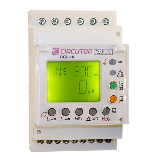
Circutor RGU-10 Instruction Manual
Electronic earth leakage protection relay
Hide thumbs
Also See for RGU-10:
- User manual (32 pages) ,
- Quick start manual (4 pages) ,
- Instruction manual (4 pages)
Table of Contents
Advertisement
Quick Links
Download this manual
See also:
User Manual
Advertisement
Table of Contents

Subscribe to Our Youtube Channel
Related Manuals for Circutor RGU-10


Summary of Contents for Circutor RGU-10
- Page 1 Electronic earth leakage protection relay RGU-10, RGU-10C INSTRUCTION MANUAL (M98203201-03-18A)
- Page 2 RGU-10, RGU-10C Instruction Manual...
-
Page 3: Safety Precautions
DISCLAIMER CIRCUTOR, SA reserves the right to make modifi cations to the device or the unit specifi ca- tions set out in this instruction manual without prior notice. CIRCUTOR, SA on its web site, supplies its customers with the latest versions of the device specifi cations and the most updated manuals. www.circutor.com CIRCUTOR, recommends using the original cables and accessories that are supplied with the device. -
Page 4: Table Of Contents
RGU-10, RGU-10C CONTENTS SAFETY PRECAUTIONS ��������������������������������������������������������������������������������������������������������������������������������������� 3 DISCLAIMER ���������������������������������������������������������������������������������������������������������������������������������������������������������� 3 CONTENTS �������������������������������������������������������������������������������������������������������������������������������������������������������������4 REVISION LOG ������������������������������������������������������������������������������������������������������������������������������������������������������� 5 SYMBOLS ��������������������������������������������������������������������������������������������������������������������������������������������������������������� 5 1�- VERIFICATIONS UPON RECEPTION ������������������������������������������������������������������������������������������������������������� 6 2�- DESCRIPTION OF THE PRODUCT ������������������������������������������������������������������������������������������������������������������ 6 3�- INSTALLING THE DEVICE ������������������������������������������������������������������������������������������������������������������������������� 8 3�1�- PRELIMINARY RECOMMENDATIONS ���������������������������������������������������������������������������������������������������� 8 3�2�- INSTALLATION �����������������������������������������������������������������������������������������������������������������������������������������... -
Page 5: Revision Log
RGU-10, RGU-10C REVISION LOG Table 1: Revision log� Date Revision Description 5/18 M98203201-03-18A New Version SYMBOLS Table 2: Symbols� Symbol Description In compliance with the relevant European directive. The device complies with the 2012/19/EC European directive. Do not dispose of the device in a household waste container at the end of its useful life. -
Page 6: 1�- Verifications Upon Reception
2�- DESCRIPTION OF THE PRODUCT The RGU-10 earth leakage relay is type A programmable electronic earth leakage protection device with two independent relays: the main output for checking the cut off device and perform- ing the protection function and the pre-alarm relay for installation prevention and maintenance. - Page 7 The measurement of earth leakage current from which the RGU-10/RGU-10C operates by indicating the instant leakage current, pre-alarm or trip is determined by the WGC series earth leakage transformers. The inner diameter of the transformer is defined by the installation’s wir-...
-
Page 8: 3�- Installing The Device
RGU-10, RGU-10C 3�- INSTALLING THE DEVICE 3.1.- PRELIMINARY RECOMMENDATIONS The operators using and handling the device must follow the safety measures established in the country where the device will be used to guarantee its safe operation, using personal protective equipment if needed. -
Page 9: 3�2�- Installation
RGU-10, RGU-10C 3.2.- INSTALLATION While the device is connected, the terminals, opening the cover or removing el- ements can expose parts that are hazardous to the touch. The device must not be used until the installation process is complete. The device is installed on a DIN rail or on a panel (drilled panel 67... -
Page 10: 3�3�- Terminals Of The Device
RGU-10, RGU-10C Figure 2: Installation of adapter accessory 3.3.- TERMINALS OF THE DEVICE Table 3:Terminal description RGU-10� Terminals of the device 1: Voltage input ON/OFF external L 9: Toroid current input 1S2 2: Voltage input ON/OFF external N 10: Power supply voltage input A1... -
Page 11: 3�4�- Connection Diagrams
RGU-10, RGU-10C 3.4.- CONNECTION DIAGRAMS Note : It is recommended that meshed cable is used to connect the toroid over large distances. 3�4�1�- CONNECTION WITH CURRENT EMISSION COIL 3�4�1�1�- Powering the device before the breaking device In the event of powering the device before the breaking device (automatic switch) in an earth leakage trip situation because of a fault, test or toroid error: 1�- Note the cause of the trip on the red display. - Page 12 RGU-10, RGU-10C Reset exterior External Reset L1 L2 L3 10 11 13 14 15 Reset Test 2 4 5 Disparo por BOBINA DE EMISIÓN - Rearme Manual UTILIZACIÓN Trip by SHUNT COIL - Manual reclose Figure 5: 400 Vac power supply...
- Page 13 RGU-10, RGU-10C 3�4�1�2�- Powering the device after the breaking device The following has to be taken into consideration in the event of powering device after the break- ing device. 1�- The breaking device has to be a manually resettable device.
- Page 14 RGU-10, RGU-10C L1 L2 L3 Reset exterior External Reset 10 11 13 14 15 Reset Test 2 4 5 Disparo por BOBINA DE EMISIÓN - Rearme Automático mediante corte de alimentación UTILIZACIÓN Trip by SHUNT COIL - Automatic reclose by power supply out...
- Page 15 RGU-10, RGU-10C 3�4�1�3�- Power supply of the device independent of the installation L1 L2 L3 10 11 13 14 15 Reset Test 2 4 5 Disparo por BOBINA DE EMISIÓN - Rearme Manual UTILIZACIÓN Trip by SHUNT COIL - Manual reclose Figure 8: 24 ���...
-
Page 16: 3�4�2�- Connection With Undervoltage Coil
RGU-10, RGU-10C 3�4�2�- CONNECTION WITH UNDERVOLTAGE COIL 3�4�2�1�- Powering the device before the breaking device This breaking device may be an automatic switch or contactor. Using a Contactor the protection is reset by pressing RESET, or by using an automatic switch. - Page 17 RGU-10, RGU-10C Reset exterior External Reset L1 L2 L3 10 11 13 14 15 Reset Test 2 4 5 Disparo por BOBINA DE MÍNINA - Rearme Manual UTILIZACIÓN Trip by UNDERVOLTAGE COIL - Manual reclose Figure 10: 400 Vac power supply...
- Page 18 RGU-10, RGU-10C 3�4�2�2�- Power supply of the device independent of the installation L1 L2 L3 10 11 13 14 15 Reset Test 2 4 5 Disparo por BOBINA DE MíNIMA - Rearme Manual UTILIZACIÓN Trip by UNDERVOLTAGE COIL - Manual reclose Figure 11: 24 ���...
-
Page 19: 3�4�3�- Connecting The Device In Positive Safety
RGU-10, RGU-10C 3�4�3�- CONNECTING THE DEVICE IN POSITIVE SAFETY This installation mode provides the most conservative protection from the point of view of per- sonal and property safety in electrical installations. With this type of device connection and setting, persons all goods are protected against faults where the earth leakage relay loses its protection capacity. - Page 20 RGU-10, RGU-10C 3�4�3�2�- Connection with current emission coil When this type of safety is used using the current emission coil, it can only be assured that the system will trip went the earth leakage relay is not operating correctly. 1�- The breaking device has the power to trip using the maximum current coil (automatic switch).
-
Page 21: 4�- Operation
RGU-10, RGU-10C 4�- OPERATION 4.1.- GENERAL DESCRIPTION DIN RAIL SMALL SIZE: PANEL ( ADAPTER ACCESSORY) 3 MODULE INSTANT CURRENT LEAKAGE BACKLIT DISPLAY LCD DISPLAY GREEN Normal operation status. RED Trip status by fault or other event. PRE-ALARM RELAY SENSITIVITY from 50 ... 80% I ∆N... -
Page 22: 4�2�- Description Of The Device
RGU-10, RGU-10C 4.2.- DESCRIPTION OF THE DEVICE The front of the equipment which is formed by the display, buttons and LEDs, is protected with a sealable plastic cover which has the appropriate holes to access the RESET, TEST and PROG keys. -
Page 23: 4�4�- Keyboard Functions
RGU-10, RGU-10C Table 5:LEDs description: Yellow LED� Yellow LED State Description There is no pre-alarm trip. Pre-alarm trip without reclosing. Pre-alarm trip in reclosing situation. flashing 4.4.- KEYBOARD FUNCTIONS The device has 7 keys, Figure 14 1�- Keys accessible with sealed cover and tool�... -
Page 24: 4�5�- Display
If the device trips through any event, the screen’s background changes to red and the reason for the trip is displayed. Figure 15: Display RGU-10� Display messages by device trip, Table 7 Table 7: Display messages by device trip... -
Page 25: 4�6�- Operation
RGU-10, RGU-10C 4.6.- OPERATION When the device is powered at its rated voltage, the green LED ON the front is on, the backlit LCD is green indicating the software and hardware version. After a short while, the version disappears and the default display values appear on the display. -
Page 26: 4�7�- Troubleshooting Or Reasons For Tripping
RGU-10, RGU-10C The RGU-10/ RG5-10C allow the display and setting of all required parameters to complete the earth leakage protection adjustment with pre-alarm and communications. Table 10: Adjustment parameters� Parameter Units Programmed pre-alarm trip delay ms / s Sensitivity of pre-alarm in % I∆ + (contact 6-5 NO) / nothing (contact 6 - 5 NC) -
Page 27: 4�7�3�- Fault Trip
RGU-10, RGU-10C 4�7�3�- FAULT TRIP When the device is tripped by a current fault, the red and yellow LED comes on and the backlit LCD is red. There remains the display of the current of the last cycle that the relay has tripped. -
Page 28: 5�- Configuration
RGU-10, RGU-10C 5�- CONFIGURATION 5.1.- DIRECT SETTING By pressing for a long time on any of the direct setting buttons, PROG mode is entered (icon on isplay) and the relay’s setting may be changed. While in PROG mode if any other direct function is used (Id, td, Std/+ y Auto), the parameter for the displayed relay can also be set. -
Page 29: 5�1�3�-Positive Security Setting Of The Main Relay
RGU-10, RGU-10C or SEL. 5�1�3�-POSITIVE SECURITY SETTING OF THE MAIN RELAY “Std”, contacts are on standby, terminals 14 - 15 (NC) and 13 - 15 (NO). “+”, contacts change status on powering the device, the + sign is displayed. Terminals 14 -15 (NO) and 13 -15 (NC). - Page 30 RGU-10, RGU-10C 5�1�4�2�- Pre-alarm time setting This is in terms of the program value in the main relay. Pressing td enters to change the values. Pressing td changes the values: 20, 50, 75, 100, 300, 500, 750 ms, 1, 3, 5 and 10 s�...
-
Page 31: 5�2�- Setting By Setup
RGU-10, RGU-10C 5.2.- SETTING BY SETUP “PROG” and the first menu option appear on the display by pressing a long time the PROG/ PAG key. Once in menu setting mode, the different text indicators appear on the display after each time PROG is pressed. When the correct menu is reached, the parameter can be changed by pressing td (rotating). -
Page 32: 5�3�- Configuration The Measurement Setup
PROG Figure 31: RGU-10 configuration menu. 5.3.- CONFIGURATION THE MEASUREMENT SETUP From measurement SETUP, the parameter settings for the RGU-10/RGU-10C can be displayed and/or changed; this may match these parameters to the requirements of the system topologies and/or applications If it is an RGU-10C, this SETUP menu is preceded by the communications SETUP menu. If there is no communications, RGU-10, is the only SETUP on the device. -
Page 33: 5�3�2�- Scale Limit
RGU-10, RGU-10C 5�3�2�- SCALE LIMIT The display shows LIM. In order to change this press PROG. The final delay scale values and the actual current sensitivity settings appear on the upper section of the screen. In order to modify the operational scale, repeatedly press the td button increasing the values of the digits on the upper section of the screen. -
Page 34: 5�4�1�- Peripheral Number
RGU-10, RGU-10C To enter setting mode the PROG key must be pressed. 5�4�1�- PERIPHERAL NUMBER The display shows PERI and the peripheral number on the upper left of the screen. To write or change the number of the peripheral repeatedly press the td button, increasing the value of the digit which is in the upper left corner. -
Page 35: 5�4�3�- Parity
RGU-10, RGU-10C Table 11: Baud rate� Value on screen Bauds 2400 4800 9600 19.2 19200 38.4 38400 54.6 54600 115000 5�4�3�- PARITY The display shows “PARI” with the set a value on the upper left of the screen. In order to change parity, repeatedly press the td key to change the values on the upper left of the screen. -
Page 36: 6�- Rs-485 Communications
RGU-10, RGU-10C 6�- RS-485 COMMUNICATIONS RGU-10C devices feature one RS-485 communications port. The device has uses the MOD- BUS RTU communications protocol as the standard protocol. 6.1.- CONNECTIONS The RS-485 cable must be wired with twisted pair cable with mesh shield (minimum 3 wires),... -
Page 37: 6�2�- Modbus Protocol
RGU-10, RGU-10C 6.2.- MODBUS PROTOCOL In the Modbus protocol, the RGU-10C uses the RTU (Remote Terminal Unit) mode. The Modbus functions implemented in the device are as follows: Function 0x04: Reading integer registers. Function 0x10: Writing multiple registers. 6�2�1� READ EXAMPLE: Function 0x04�... -
Page 38: 6�2�2� Write Example : Function 0X10
RGU-10, RGU-10C 6�2�2� WRITE EXAMPLE : Function 0x10� Query: Registers Initial No� of Address Function Nº de Bytes Register registers Nº1 Nº2 Nº3 Nº4 Nº5 0000 0005 0001 0003 0000 003C 0000 FF64 Address: 01, Peripheral number: 1. Function: 10, Writing multiple registers. - Page 39 RGU-10, RGU-10C Table 12 (Continuation) : Modbus memory map Reading / Parameter Symbol Address Values Units Writing Series No. (HI) 000B 18AD - 188C Series No. (LO) 000C 0000 - FFFF Device version 000D 0 -100 off - on (main)
-
Page 40: 7�- Technical Features
Cut off power for DC loads Note: Circutor guarantees that the RGU-10 / RGU-10C device complies with a response time of less than 30 ms to 5In, and in combination with the selected cutting element must guarantee a total cut-off time of less than 40 ms to comply with the IEC 60947-2-M standard. - Page 41 0.4x2.5x80 mm 67,9 52,5 43,5 Figure 33: RGU-10 dimensions� Safety / Standard Designed for installations category III 300 V~ (EN 61010) Protection against electric shock by class II double insulation� Electrical accessories - Residual current monitors for household and...
-
Page 42: 8�- Technical Service
• CIRCUTOR accepts no liability due to the possible damage to the unit or other parts of the installation, nor will it cover any possible sanctions derived from a pos- sible failure, improper installation or “improper usage”... -
Page 43: 10�- Ce Certificate
RGU-10, RGU-10C 10�- CE CERTIFICATE Instruction Manual... - Page 44 RGU-10, RGU-10C Instruction Manual...
- Page 45 RGU-10, RGU-10C Instruction Manual...
- Page 46 CIRCUTOR, SA Vial Sant Jordi, s/n 08232 - Viladecavalls (Barcelona) Tel: (+34) 93 745 29 00 - Fax: (+34) 93 745 29 14 www.circutor.es central@circutor.com...
Need help?
Do you have a question about the RGU-10 and is the answer not in the manual?
Questions and answers