Advertisement
Quick Links
Advertisement

Related Manuals for Xebex Fitness Air Bike ABVR-1


Summary of Contents for Xebex Fitness Air Bike ABVR-1
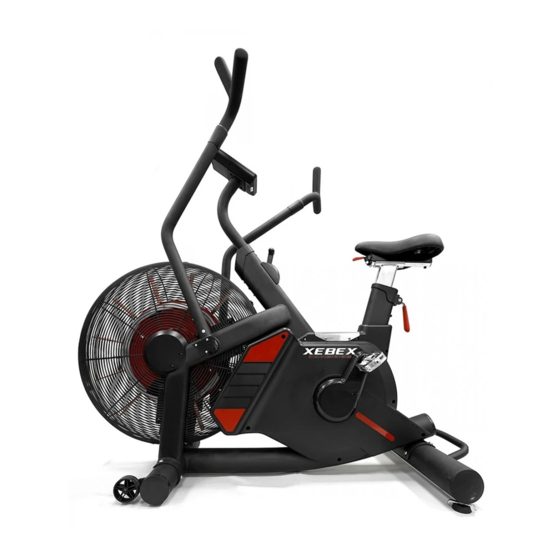
- Page 1 AIR BIKE ABVR-1...
-
Page 2: Assembly Preparation
ASSEMBLY PREPARATION To ensure ease of product assembly, please take time to verify the size and quantities of all required assembly hard- ware. Use the itemized parts listing and hardware chart for reference. The product assembly process has been documented in easy to follow steps. Please read all assembly instructions carefully. - Page 3 Front stabilizer Main frame Rear stabilizer Swing Handle Bar Console Console Tube Pedal (H2) AL Triangle Tube (H3) Triangle Tube (H1) Console Tube Cover End Cap (H4) Bolt (H5) Bolt (H6) Sleeve (H7) Flat Washer M10x20mm M8x40mm 10x20x1.5t (H8) Bolt (H9) Tapping Screw (H10) Bolt M10x100mm...
- Page 4 ASSEMBLE THE FRONT & REAR STABILIZER Step 1. Loosen the two screws (H4) from the front & rear paper tube. The paper tube is used for packaging purposes only and won't be needed again during/after the assembly. Step 2. Attach the front stabilizer (B) onto and secure it with screws (H4).
- Page 5 ASSEMBLE LEFT & RIGHT SWING HANDLE BARS & FOOT SUPPORT Step1. Attach right swing handle bar (D2) with main frame (A) with Bolts(H5). Step2. Insert the sleeve (H6) into the foot support (H2). Then,attach the foot support (H2) with main frame (A) with a washer (H7) and Bolt (H8) Step3.
- Page 6 ASSEMBLE THE CONSOLE TUBE WITH MAIN FRAME Step1. Insert the console tube cover (H1) onto the main frame (A). Step2. Connect the sensor wire (E2) with sensor wire (A7). Then,insert the console tube (E) into the main frame (A). Step3. Secure with Bolts (H10).
- Page 8 Sticker Sticker Sticker Sticker Sticker Magnet E Clip Aluminum Plate Aluminum Pad Seat Fan Wheel Axle-- Magnet Base Magnet Set...
- Page 9 Tension Adjust Bar Tapping Screw Bolt M6x8mm Aluminum Triangle Tube...
Need help?
Do you have a question about the Air Bike ABVR-1 and is the answer not in the manual?
Questions and answers