
Subscribe to Our Youtube Channel
Related Manuals for Trio Datacom ER450

Summary of Contents for Trio Datacom ER450
- Page 1 E Series Data Radio – User Manual User Manual E Series Data Radio ER450 Remote Data Radio EB450 Base Station EH450 Hot Standby Base Station www.triodatacom.com Issue 11: Jun 2009 Page 1...
-
Page 2: Table Of Contents
Examples of Predictive Path Modelling Data Connectivity Power Supply and Environmental Considerations Physical Dimensions - Remote Data Radio - ER450 Physical Dimensions - Base Station - EB450 Physical Dimensions - Hot Standby Base Station - EH450 Part E – Getting Started... - Page 3 E Series Data Radio – User Manual SECTION 1 Part A - Preface Part B - E Series Overview Part C - Applications Part D - System Planning and Design Part E - Getting Started Part F - Operational Features Part G - Commissioning Part H - Maintenance Page 3...
-
Page 4: Part A - Preface
The warranty does not cover modifications to software. All equipment for repair under warranty must be returned freight paid to Trio DataCom Pty Ltd or to such other place as Trio DataCom Pty Ltd shall nominate. Following repair or replacement the equipment shall be returned to the customer freight forward. -
Page 5: Compliance Information
1 minute. FCC Notice (Hot Standby Controller Only) Trio Datacom declares that the E Series radio modem is in compliance with the essential requirements and other relevant This equipment has been tested and found to comply with the provisions of the Directive 1999/5/EC. -
Page 6: Related Products
This symbol on the product or its packaging indicates that this product must not be disposed of with other waste. Instead, it is Applies to models ER450-xxxxx-xHx(CSA Marked) your responsibility to dispose of your waste equipment by handing This product is available for use in Class I, Division 2, Groups it over to a designated collection point for the recycling of waste A, B, C &... -
Page 7: Part B - E Series Overview
Compatible with most industry standard data protocols. eg: MODBUS, DNP-3, IEC 870, SEL Mirrored Bits, etc. • Independent system port for interruption free programming and diagnostics (in addition to two (2) user ports). ER450 Remote Radio • 9600bps in 12.5 kHz radio channels with ETSI specifications. •... - Page 8 • Digital plug in order wire option for commissioning and occasional voice communications without the need to inhibit users application data. Features and Benefits of ER450 Remote Data Radio • Optional full duplex capable remote – separate Tx and Rx ports for connection to an external duplexer.
-
Page 9: Model Number Codes
Options* = Diagnostics and Encryption - [DIAGS/E or DIAGS/EH] (E Series Only) *** = Full Duplex Operation and Diagnostics [ERFD450 & DIAGS/E] (ER450 only) = Full Duplex Operation, Diagnostics and Encryption (ER450 only) *** = Low Power Module + Diagnostics (MR450 only) = Diagnostics RF Channel Data Rate &... -
Page 10: Standard Accessories
(N Type – Tx Port, SMA - Type Rx Port) Note: Requires external duplexer Frequencies must be specified at time of order. ERFDTRAY 19” Rack Tray for Mounting of ER450 Full Power Supplies Duplex Radio and External Band Reject Duplexer PS13V82A Power Supply 13.8V 2A 240VAC... -
Page 11: Part C - Applications
E Series Data Radio – User Manual Part C – Applications Part C – Applications Application Detail Generic Connectivity The E Series has been designed for SCADA and telemetry SCADA Systems applications, and any other applications that use an ASCII communications protocol, and which connect physically using the This is where one or more centralised control sites are used RS232 interface standard (although converters can be used to... -
Page 12: Systems Architecture
E Series Data Radio – User Manual Part C – Applications Systems Architecture Point-to-Point This simple system architecture provides a virtual connection between the two points, similar to a cable. Dependent of the hardware chosen, it is possible to provide a full duplex connection (i.e. - Page 13 E Series Data Radio – User Manual Part C – Applications (See Part F - Operational Features) data transfer on the system. Digipeater Systems Backbone Store and Forward Systems This configuration is used where all sites are required to Store and forward is used as a way of extending RF coverage by communicate via a repeater site.
-
Page 14: Part D - System Planning And Design
E Series Data Radio – User Manual Part D – System Planning and Design Part D – System Planning and Design Selecting Antennas Understanding RF Path Requirements A radio modem needs a minimum amount of received RF signal to operate reliably and provide adequate data throughput. In most cases, spectrum regulatory authorities will also define or limit the amount of signal that can be transmitted, and the transmitted power will decay with distance and other factors, as it... -
Page 15: Examples Of Predictive Path Modelling
Path Length (km) 115.99 Free Space Loss (dB) 0.00 Diffraction Loss (dB) 103.75 103.75 Net Path Loss (dB) Radio Type Model EB450 ER450 5.00 1.00 TX Power (watts) 6.99 0.00 TX Power (dBW) 6.71 4.63 Effective Radiated Power (watts) Effective Radiated Power (dBW) 8.27... - Page 16 Path Length (km) 122.85 Free Space Loss (dB) Diffraction Loss (dB) 22.94 Net Path Loss (dB) 133.55 133.55 Radio Type Model EB450 ER450 5.00 1.00 TX Power (watts) TX Power (dBW) 6.99 0.00 Effective Radiated Power (watts) 6.72 4.64 Effective Radiated Power (dBW) 8.27...
-
Page 17: Antenna Placement
E Series Data Radio – User Manual Part D – System Planning and Design There are basically two types of antennas – omni-directional and Tuning the Antenna directional. Many antennas are manufactured for use over a wide frequency Omnidirectional antennas are designed to radiate signal in a 360 range. -
Page 18: Data Connectivity
E Series Data Radio – User Manual Part D – System Planning and Design RF Feeders and Protection Data Connectivity The antenna is connected to the radio modem by way of an The V24 Standard RF feeder. In choosing the feeder type, one must compromise between the loss caused by the feeder, and the cost, flexibility, and The E Series radio modems provide two asynchronous V24 bulk of lower loss feeders. - Page 19 E Series Data Radio – User Manual Part D – System Planning and Design Cable Wiring Diagrams Page 19...
- Page 20 E Series Data Radio – User Manual Part D – System Planning and Design Cable Wiring Diagrams RS232 Connector Pin outs (DCE) Port A and B, Female DB9 Page 20...
-
Page 21: Power Supply And Environmental Considerations
- Specifications for more details of the power supply requirements. Caution: There is NO readily serviceable internal fuse, and therefore the radio modem MUST be externally fused with a fuse and fuse holder (ER450: 3 amp fast-blow fuse, EB450: 5 amp fast-blow fuse). Page 21... -
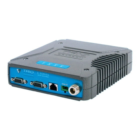
Page 22: Physical Dimensions - Remote Data Radio - Er450
E Series Data Radio – User Manual Part D – System Planning and Design Physical Dimensions - Remote Data Radio - ER450 Page 22... -
Page 23: Physical Dimensions - Base Station - Eb450
E Series Data Radio – User Manual Part D – System Planning and Design Physical Dimensions - Base Station - EB450 Page 23... -
Page 24: Physical Dimensions - Hot Standby Base Station - Eh450
E Series Data Radio – User Manual Part D – System Planning and Design Physical Dimensions - Hot Standby Base Station - EH450 Page 24... -
Page 25: Part E - Getting Started
Mounting and Environmental Considerations Introduction The ER450 radio comes complete with a mounting cradle and is attached to a panel or tray by means of screws or bolts, using the Welcome to the ER450 Quick Start Guide. This guide provides hole slots provided. - Page 26 E Series Data Radio – User Manual Part E – Getting Started - ER450 ER450 Connections Layout The TVIEW+ Cable is a standard CAT 5 RJ-45 (Male) to RJ-45 (Male) patch cable. It is intented for RS232 serial communications only and should not be connected directly into an ethernet port of a PC.
- Page 27 E Series Data Radio – User Manual Part E – Getting Started - ER450 User Interfaces – Ports A & B RS232 Connector Pin outs (DCE) Port A and B, Female DB9 Each user port (A & B) is wired as a RS232 DCE, configurable for no handshaking (3-wire) interface, or for hardware or software (X- on/X-off) flow control.
-
Page 28: Power Supply Requirements
The configuration wizard can be used to provide Quick Start and therefore the radio modem MUST be externally fused generic templates for the types of systems architecture you wish with a fuse and fuse holder (ER450: 3 amp fast-blow fuse, to employ. EB450: 5 amp fast-blow fuse). - Page 29 E Series Data Radio – User Manual Part E – Getting Started- ER450 Optimising the Antenna for best RX LED Indicators & Test Outputs signal LED Legend Once the unit is operational, it is important to optimise the antenna tuning.
- Page 30 E Series Data Radio – User Manual Part E – Getting Started- ER450 Received Signal Indicator Verifying Operational Health It is possible to verify the operation of the radio modem using the LED Legend indicators provided by the unit. The state of the transmitter and receiver, and data flow can be interpreted by the indicator LEDs The “RX/SYNC”...
-
Page 31: Eb450 Quick Start Guide
Communications Ports All permanent connections are made at the rear of the unit. This See ER450 Quick Start Guide Section includes: Power, Antenna, Communications Ports, Digital I/O and System Port. The front panel has an additional System Port Power Supply and Protection connection point for easy access. - Page 32 E Series Data Radio – User Manual Part E – Getting Started - EB450 Typical Radio Setup TVIEW+ Diagnostics will recognise an input as being ON when the Digital Inputs and Outputs switch is closed. If the switch is open (or not connected) TVIEW+ The EB450 provides a facility for two channels of digital user inputs diagnostics will recognise the inputs as being OFF.
-
Page 33: Test Mode
E Series Data Radio – User Manual Part E – Getting Started - EB450 LED Indicators & Test outputs Bar Graph Indicators The bar graph indicators on the front panel provide variable Radio is Powered information regarding the performance of the Base Station. To If all the LEDs are off, no power is reaching the radio modem. -
Page 34: Eh450 Quick Start Guide
E Series Data Radio – User Manual Part E – Getting Started - EH450 EH450 Quick Start Guide Features and Benefits • Individual and identical base stations with separate control Introduction logic changeover panel Welcome to the Quick Start Guide for the EH450 Hot Standby •... - Page 35 E Series Data Radio – User Manual Part E – Getting Started - EH450 event will occur due to lost communications with the Hot Standby Operational Description Controller. The Hot Standby Controller (HSC) unit is a 1RU rack mounted module that interfaces to two physically separate base stations Mounting and Environmental (each 2RU rack mounted modules) via a number of RF and data Considerations...
- Page 36 System Port connects directly The A & B Data Ports and System Ports of each Base Station to your local PC. See ER450 Quick Start Guide Section for further connect directly to the Hot Standby Controller units corresponding details.
- Page 37 Part E – Getting Started - EH450 Connecting Antennas and RF Feeders There are 3 primary antenna connection options. All connectors used are standard N Type sockets. See figures below for further details. See ER450 Quick Start Guide for detailed wiring information. Page 37...
-
Page 38: Front Panel Operation
E Series Data Radio – User Manual Part E – Getting Started - EH450 Front Panel Operation Switches Alarm Status LEDs There are 10 alarm LEDs on the front panel, five for base 1 and Select Switch five for base 2. These LEDs provide a general indication of base The 3 position switch (1 / Auto / 2) on the front panel provides the station status. -
Page 39: Part F - Operational Features
E Series Data Radio – User Manual Part F – Operational Features Part F - Operational Features Multistream functionality (SID RF Carrier Detect RSSI based Collision Avoidance codes) In half duplex systems, the receiver’s RF carrier detect is used to The E Series sends data messages in packets. -
Page 40: Part G - Commissioning
E Series Data Radio – User Manual Part G – Commissioning Part G – Commissioning Check DC power connector for correct voltage (10-16VDC) and Antenna Alignment and RSSI polarity, BEFORE plugging in the power connector. Testing Power-up Once the RXSIG LED is lit, it is possible to confirm RX signal strength and align a directional antenna by monitoring the RSSI Upon power up, the radio will self test and shortly after the green output. -
Page 41: Part H - Maintenance
E Series Data Radio – User Manual Part H – Maintenance Part H – Maintenance Routine Maintenance Considerations The E Series hardware itself does not require routine maintenance. However all radio products contain crystal frequency references, and the stability of these crystals changes with time. The effect of this is that the product will slowly drift off frequency, and eventually it will require re-calibration. -
Page 42: Part I - Tview+ Management Suite - Programmer
The programmer is used to set configuration parameters within serial port (See Appendix C for details) DB9 connector. the ER450 data radio modem and EB450 base station. The utility permits configuration of modems connected directly to the PC as Software well as over the air to a remote unit. -
Page 43: Tview+ Front Panel
E Series Data Radio – User Manual Part I – TVIEW+ Management Suite - Programmer Programmer STEP 2: Installation - TView Diagnostic Software (Optional) Main Window Note: If a previous version of the “TView WinDiags” software has been installed on your PC, you must uninstall it via Control Panel When first started the programmer is in file mode as indicated by “Add/Remove Programs”. -
Page 44: File Menu
E Series Data Radio – User Manual Part I – TVIEW+ Management Suite - Programmer Pull Down Menus and Toolbar Buttons Exit (also available on the toolbar) This function terminates the program. The user is requested to The items on the pull-down menus can be selected either directly confirm this selection before exiting the application. - Page 45 E Series Data Radio – User Manual Part I – TVIEW+ Management Suite - Programmer The user is prompted via a series of dialogue windows to select the This dialog provides a facility for reversing any remote desired configuration that can then be written to the unit (remote configuration changes that cause unexpected results resulting in radio or base station).
- Page 46 E Series Data Radio – User Manual Part I – TVIEW+ Management Suite - Programmer Packet Layer (Packet Modes Only) Settings This menu permits selection of the PC serial port (COM1 to COM4) There are two standard configurations and a custom configuration to be used for communications with the unit.
- Page 47 E Series Data Radio – User Manual Part I – TVIEW+ Management Suite - Programmer The fields which can be configured are: • Character Input timer: Set the input timer value in ms or enter zero to disable. Range 0 - 255. •...
- Page 48 E Series Data Radio – User Manual Part I – TVIEW+ Management Suite - Programmer • Disabled The CTS is a signal from the modem to the host informing the This selection disables the DCD output on the port. This selection host that the modem is able to accept incoming data on the is not permissible if hardware based flow control has been TXD line.
- Page 49 E Series Data Radio – User Manual Part I – TVIEW+ Management Suite - Programmer There are two methods for setting the power. keys, or a typed in value, can be used to select the required mute level in dBm steps. Whilst a session is in progress with a unit the •...
- Page 50 E Series Data Radio – User Manual Part I – TVIEW+ Management Suite - Programmer PTT Delay : the amount of time between RTS enabled and Legacy Modulation Schemes: Some modulation types are the transmitter becoming active. specifically for backwards compatibility. These include Bell 202 modes and D Series compatibility modes.
- Page 51 E Series Data Radio – User Manual Part I – TVIEW+ Management Suite - Programmer In this way, Port “A” and Port “B” can be assigned different SID PTT Timeout codes, thereby separating the data streams. The PTT timeout facility is used to disable the transmitter if it Two SID codes values are available for each user port RXSID and exceeds the designated time.
- Page 52 E Series Data Radio – User Manual Part I – TVIEW+ Management Suite - Programmer Polled Diagnostics The Diagnostics Processor can be configured to listen for diagnostics on a range of SID codes. The factory default is SID code 0 (From Stream 0 To Stream 0). The diagnostics responses are sent back over the same stream as the questions.
- Page 53 E Series Data Radio – User Manual Part I – TVIEW+ Management Suite - Programmer When a radio configuration is read from a radio that already • Mode – “Master” or “Remote”. When the master unit has AES encryption enabled, the encryption key will be shown receives a valid transmission from a remote unit it sets the as “**************”...
-
Page 54: Status Bar
Base Firmware Pack refers to the firmware package version installed in the base station (front panel) controller Radio Model refers to the type of unit. The ER450 is a remote which is separate to the radio installed. There are several unit and the EE450 is a exciter inside a base station unit. -
Page 55: Appendix A - Firmware Updates
E Series Data Radio – User Manual Part J – Appendices Appendix A - Firmware Updates Firmware Update for E Series Base Station Exciters - Gen II (Serial No 56000 or above) Firmware Update Overview Click on the “E Series Firmware Update” Start the firmware update Firmware updates are performed on a unit connected locally utility from the TView+ front panel. -
Page 56: Installation Instructions
E Series Data Radio – User Manual Part K – Appendices Select the file containing the firmware update package using Hot Standby Controller Firmware the “Open Firmware Package” button at the bottom of the main Update window. After opening the file, the browse window will close and a Installation Instructions: description of the firmware package will appear in the main window. -
Page 57: Part J - Specifications
Management and Diagnostic Information subject to change without notice. < 1x10⁻⁶ @ -106 dBm (19,200 bps) © Copyright 2008 Trio Datacom Pty Ltd. Windows GUI Software Encryption: 128-bit AES encryption Over-the-air re-confi guration of All rights reserved. Issue 11-2008 DIAGS/E Network Management and Collision Avoidance: Trio Datacom’s... - Page 58 Windows GUI Software < 1x10⁻⁶ @ -108 dBm (9600 bps) Information subject to change without notice. Over-the-air re-configuration of © Copyright 2009 Trio Datacom Pty Ltd. < 1x10⁻⁶ @ -106 dBm (19,200 bps) DIAGS/E Network Management and user parameters. All rights reserved. Issue 03-2009...
- Page 59 Information subject to change without notice. Network wide operation from any Voice Module Data Buffer: 16 kbyte of on-board RAM © Copyright 2009 Trio Datacom Pty Ltd. remote terminal. TVIEW+™ Configuration, Network All rights reserved. Issue 04-2009 Bit Error Rate:...
-
Page 60: Part K - Support Options
Part K – Support Options Website Information Service Department The Trio DataCom website support contains links to e-mail and The Service department may be contacted by e-mail to telephone support, technical notes, manuals, software updates. service@triodatacom.com , or by telephone.
Need help?
Do you have a question about the ER450 and is the answer not in the manual?
Questions and answers