Advertisement
Table of Contents
- 1 Table of Contents
- 2 About this Publication
- 3 Before You Begin
- 4 Determine Module Slot Location
- 5 Set the Network Address
- 6 Install the Module
- 7 Connect the Module to the Ethernet/Ip Network
- 8 Program the Module Via the USB Port
- 9 Configure the Module
- 10 Apply Chassis Power
- 11 Check Power Supply and Module Status
- 12 Install or Remove the Module under Power
- 13 Interpret the Status Indicators
- 14 Specifications
- Download this manual
Installation Instructions
ControlLogix EtherNet/IP Module
Catalog Number 1756-EN2T
Topic
About This Publication
Use this publication as a guide to install the module. This publication describes
hardware installation only. For configuration information, refer to the
EtherNet/IP Modules in Logix5000 Control Systems User Manual, publication
ENET-UM001. View or download this publication at
http://www.rockwellautomation.com/literature.
Page
1
7
8
9
11
12
14
15
15
16
17
19
22
Advertisement
Table of Contents

Subscribe to Our Youtube Channel
Related Manuals for Allen-Bradley 1756-EN2T


Summary of Contents for Allen-Bradley 1756-EN2T
-
Page 1: Table Of Contents
Installation Instructions ControlLogix EtherNet/IP Module Catalog Number 1756-EN2T Topic Page About This Publication Before You Begin Determine Module Slot Location Set the Network Address Install the Module Connect the Module to the EtherNet/IP Network Program the Module via the USB Port... - Page 2 2 ControlLogix EtherNet/IP Module Important User Information Solid-state equipment has operational characteristics differing from those of electromechanical equipment. Safety Guidelines for the Application, Installation and Maintenance of Solid State Controls (Publication SGI-1.1 available from your local Rockwell Automation sales office or online at http://www.rockwellautomation.com/literature/) describes some important differences between solid-state equipment and hard-wired electromechanical devices.
- Page 3 ControlLogix EtherNet/IP Module 3 North American Hazardous Location Approval The following information applies Informations sur l’utilisation de cet when operating this equipment in équipement en environnements hazardous locations. dangereux. Products marked “CL I, DIV 2, GP A, B, C, D” are Les produits marqués "CL I, DIV 2, GP A, B, C, D"...
- Page 4 4 ControlLogix EtherNet/IP Module Environment and Enclosure ATTENTION: This equipment is intended for use in a Pollution Degree 2 industrial environment, in overvoltage Category II applications (as defined in IEC 60664-1), at altitudes up to 2000 m (6562 ft) without derating. This equipment is considered Group 1, Class A industrial equipment according to IEC/CISPR 11.
- Page 5 ControlLogix EtherNet/IP Module 5 Prevent Electrostatic Discharge ATTENTION: This equipment is sensitive to electrostatic discharge, which can cause internal damage and affect normal operation. Follow these guidelines when you handle this equipment: • Touch a grounded object to discharge potential static. •...
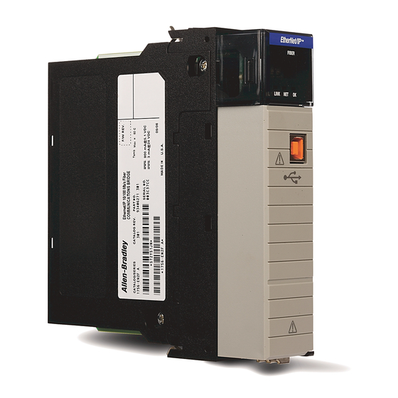
- Page 6 6 ControlLogix EtherNet/IP Module About the Module Use this figure to identify the external features of the module. EtherNet/IP 10/100 BASE T LINK NET OK 31587-M Item Description Item Description Top view Front of module Backplane connector RJ45 cable connector (on underside of module) Side view USB port...
-
Page 7: Before You Begin
ControlLogix EtherNet/IP Module 7 Before You Begin Before you install the module, you must install and connect a ControlLogix chassis and power supply. 20805-M Item Description Item Description 1756-A4 chassis Power supply To install these products, refer to these publications. Chassis Type Chassis Power Supply... -
Page 8: Determine Module Slot Location
Install the module in any slot in the ControlLogix chassis. You can install multiple 1756-EN2T modules in the same chassis. The following figure shows chassis slot numbering in a four-slot chassis. Slot 0 is the first slot and is always the leftmost slot in the rack. -
Page 9: Set The Network Address
ControlLogix EtherNet/IP Module 9 Set the Network Address The module ships with the rotary switches set to 999 and BOOTP enabled. You can set the network Internet Protocol (IP) address three ways. • Use the rotary switches on the top of the module. •... - Page 10 10 ControlLogix EtherNet/IP Module To reset the module to its initial out-of-the-box settings, reset the switches to 888 and cycle power. Do not use the 888 switch setting during normal module operation. IMPORTANT After cycling power with the switches set to 888, remove the module and set the switches to their final value.
-
Page 11: Install The Module
ControlLogix EtherNet/IP Module 11 Install the Module Follow this procedure to install the module. 1. Align the circuit board with top and bottom guides in the chassis. Item Description Circuit board 2. Slide the module into the chassis. Rockwell Automation Publication 1756-IN603C-EN-P - April 2010... -
Page 12: Connect The Module To The Ethernet/Ip Network
12 ControlLogix EtherNet/IP Module Make sure that the module backplane connector properly connects to the chassis backplane. The module is properly installed when it is flush with the power supply or other installed modules. Connect the Module to the EtherNet/IP Network WARNING: If you connect or disconnect the communication cable with power applied to this module or any device on the network, an electrical arc can occur. - Page 13 ControlLogix EtherNet/IP Module 13 Item Description Item Description USB port RJ45 connector (underneath module) We recommend connecting the module to the network via a IMPORTANT 100 MB Ethernet switch, which will reduce collisions and lost packets and increase network bandwidth. For detailed EtherNet/IP connection information, see the following publications: •...
-
Page 14: Program The Module Via The Usb Port
14 ControlLogix EtherNet/IP Module Program the Module via the USB Port WARNING: The USB port is intended for temporary local programming purposes only and is not intended for permanent connection. If you connect or disconnect the USB cable with power applied to this module or any device on the USB network, an electrical arc can occur. -
Page 15: Configure The Module
ControlLogix EtherNet/IP Module 15 Configure the Module Follow these steps to configure the module. 1. In RSLogix 5000 software, from the Controller Organizer, select New Module. 2. Select the module you want to configure. For more configuration information, refer to the EtherNet/IP Modules in Logix5000 Control Systems User Manual, publication ENET-UM001. -
Page 16: Check Power Supply And Module Status
16 ControlLogix EtherNet/IP Module Check Power Supply and Module Status Check the status indicators and alphanumeric display to determine whether the power supply and module are operating properly. LINK NET OK 31281-M Item Description Item Description OK indicator is red during self-test, NET status indicator then green LINK status indicator... -
Page 17: Install Or Remove The Module Under Power
ControlLogix EtherNet/IP Module 17 The alphanumeric display should cycle through these states: • TEST • PASS • OK • REV x.x where x.x is the module’s firmware revision. The display then alternates between OK and the module’s EtherNet/IP address. Install or Remove the Module Under Power You can install or remove this module while chassis power is applied. - Page 18 18 ControlLogix EtherNet/IP Module 2. Slide the module out of the chassis. If you want to replace an existing module with an identical one, and you IMPORTANT want to resume identical system operation, you must install the new module in the same slot. Rockwell Automation Publication 1756-IN603C-EN-P - April 2010...
-
Page 19: Interpret The Status Indicators
ControlLogix EtherNet/IP Module 19 Interpret the Status Indicators If the alphanumeric display and status indicators do not sequence through the expected states, refer to these tables. The three bi-color (red/green) status indicators on the module provide diagnostic information about the module and its connections to the network. - Page 20 20 ControlLogix EtherNet/IP Module Status Indicators Indicator Status Description The module is not powered. Verify that there is chassis power and that the module is completely inserted into the chassis and backplane. The module does not have a valid IP address. Make sure the module has been configured with a valid IP address.
- Page 21 ControlLogix EtherNet/IP Module 21 Status Indicators Indicator Status Description Verify that the module has 24V DC chassis power and that the module is completely inserted into chassis and backplane. Flashing green The module is not configured. Green The module is operating correctly. Flashing red The module detected a recoverable fault.
-
Page 22: Specifications
22 ControlLogix EtherNet/IP Module Specifications Technical Specifications - 1756-EN2T Attribute 1756-EN2T Enclosure type rating None (open-style) Module location Any slot in the ControlLogix chassis Backplane current 1 A at 5.1V DC Backplane current 3 mA at 24V DC Isolation voltage... - Page 23 ControlLogix EtherNet/IP Module 23 Environmental Specifications - 1756-EN2T Attribute 1756-EN2T Temperature, operating 0…60 °C (32…140 °F) • IEC 60068-2-1 (Test Ad, Operating Cold) • IEC 60068-2-2 (Test Bd, Operating Dry Heat) • IEC 60068-2-14 (Test Nb, Operating Thermal Shock) Temperature, nonoperating 40…85 °C (-40…185 °F)
- Page 24 24 ControlLogix EtherNet/IP Module Environmental Specifications - 1756-EN2T Attribute 1756-EN2T Immunity, conducted RF 10V rms with 1 kHz sine-wave 80%AM from 150 • IEC 61000-4-6 kHz…80 MHz Certifications - 1756-EN2T Certifications 1756-EN2T (when product is marked) c-UL-us • UL Listed Industrial Control Equipment, certified for US and Canada.
- Page 25 ControlLogix EtherNet/IP Module 25 Additional Resources These documents contain additional information concerning related Rockwell Automation products. Resource Description Industrial Automation Wiring and Grounding Provides general guidelines for installing a Guidelines, publication 1770-4.1 Rockwell Automation industrial system EtherNet/IP Modules in Logix5000 Control Contains information about how to use Systems User Manual, publication EtherNet/IP modules with various...
- Page 26 26 ControlLogix EtherNet/IP Module Notes: Rockwell Automation Publication 1756-IN603C-EN-P - April 2010...
- Page 27 ControlLogix EtherNet/IP Module 27 Notes: Rockwell Automation Publication 1756-IN603C-EN-P - April 2010...
- Page 28 Your comments will help us serve your documentation needs better. If you have any suggestions on how to improve this document, complete this form, publication RA-DU002, available at http://www.rockwellautomation.com/literature. Allen-Bradley, ControlLogix, Rockwell Software, Rockwell Automation, and TechConnect are trademarks of Rockwell Automation, Inc. Trademarks not belonging to Rockwell Automation are property of their respective companies.
Need help?
Do you have a question about the 1756-EN2T and is the answer not in the manual?
Questions and answers