
Related Manuals for Brivis ZonePlus B061006

Summary of Contents for Brivis ZonePlus B061006
- Page 1 Brivis ZonePlus Installer’s Manual PLEASE READ THESE INSTRUCTIONS CAREFULLY BEFORE INSTALLING THIS PRODUCT...
- Page 2 Brivis ZonePlus 4-Zone Control Kit Table 1: Contents of ZonePlus Kit - Brivis Part No. B061006 Brivis Part No. Description Scope This manual is intended to be used as a guide to the design, B022890 NC-6 Networker installation and commissioning of Brivis ZonePlus, a Zoning Control NT-1 Remote Temperature System for Brivis Ducted Heating and Cooling equipment.
-
Page 3: Table Of Contents
7.1 SETTING THE TIME & DAY ..........18 5.4 NT-1 Remote Temperature Sensor Installation....8 7.2 System Operation............19 5.5 Brivis 516 Zone Module Installation ........9 7.3 Product and Warranty Registration .........19 5.6 Brivis N-PM1 Power Module Installation ......9 7.4 Service Notification Message ..........19 5.7 Heater Thermistor Installation.......... - Page 4 Adaptive Zoning (non-ZonePlus Control System) Multi Temperature Set Point (MTSP) ZonePlus System One Brivis Networker Controller with zones, the ON and OFF times of The zone temperature set point can be set independently across all which are controlled by the Networker.
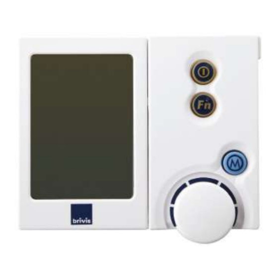
- Page 5 Diagram 1a. NC-6 Networker – Key Functions Set Temperature Room (zone) Temperature Zone Selected* Digital Clock On / Off Advance Period Symbol Set Temp Zone Key* Marker Flame Auto Program Symbol or Manual Auto Program Mode or Manual (Heating / Cooling) Mode Zone Keys** Selected...
- Page 6 Diagram 1b. NC-6 and NT-1 – Physical Characteristics Item Description Slot for wall mounting screw Front face retaining clip Slot for 2-wire bus cable 2-wire bus terminal block (TW1 & TW2) NT-1 Sensor LED...
-
Page 7: Application
• keep the sound produced by the system low enough that occupants do not find it objectionable • Brivis StarPro Ducted Gas Heaters produced after 20 May 2013 • seamlessly interface with and protect the Brivis heating and cooling (serial number greater than 995000) climate system •... -
Page 8: Designing The Comfort System
Ambient Design Temperatures b. Calculate peak heating and cooling load estimates for each zone (e.g. Multi Temperature Set Point - Design Framework: Brivis SuperSizeGuide) • Each zone has independent temperature set points c. Calculate cooling BLOCK LOAD (maximum simultaneous load) •... -
Page 9: General Installation Considerations
• Ensure that the 2-wire bus cable is routed in a protected and safe manner, away from mains power cabling • For additional product information refer to the Brivis product’s specific Installer Manual Note: Unless otherwise specified, all instructions regarding ‘cooling’... -
Page 10: Installation
Note: Do not install the wiring with the power turned on, as this may cause the fuse to blow on the Heater Control Board. NC-6, Brivis Part No: B022890 1. Backing Plate Removal 5.2 NC-6 and NT-1 Interconnecting Wiring •... -
Page 11: Remote Temperature Sensor Installation
• Draw both wires (2x ‘figure 8’ cable) from the wall cavity and feed them through the large slot in the backing plate • Connect the 2-wire bus cable from the heater to the NC-6 NT-1, Brivis Part No: B024891 brivis TW1 and TW2 terminals in the same block •... -
Page 12: Brivis 516 Zone Module Installation
CONTROL BOARD 5.5 Brivis 516 Zone Module Installation N-PM1 240V, If a Brivis 516 low voltage Zone Module is required (see Table 50Hz 2-Wire Bus Plug 2, p.6), install a 240VAC fixed switched GPO, installed adjacent to the switched GPO for the heater. -
Page 13: Heater Thermistor Installation
• For Dual Comfort systems (Brivis StarPro Heating and Brivis ICE Add-On applications), the heater thermistor must be installed in the discharge pop (outlet) of the cooling coil. Refer to the associated Brivis ICE Installer Manual for details • Amongst other primary functions, this thermistor also provides Low Temperature Limit protection. -
Page 14: Configuration And Parameter Settings
6.0 CONFIGURATION AND PARAMETER Table 3: Standard 4-Zone System Configuration SETTINGS Sensor Sensor To modify To configure the system and set parameters follow these Sensor Sensor ID steps: Zone ID Set NT-1 Sensor IDs Type Factory System System Set NC-6 Sensor IDs Setting Setting Setting... -
Page 15: Setting Nt-1 Sensor Identification
6.1.1 Setting NT-1 Sensor Identification 6.2 ZonePlus with Multiple NC-6 and NT-1 Sensors When the system contains more than one NT-1 device the sensor identification parameter setting for additional sensors Table 4: 4-Zone System Configuration with 2xNC-6 and 2x must be changed using the Jumper inside the NT-1. NT-1 (example) Sensor Sensor... -
Page 16: Zoneplus With All Nc-6 Controllers
Setting Sensor Identification on an NC-6 when Table 5: 4-Zone System Using All NC-6 Controllers (example) used as a Slave (refer Table 4. example) • Determine which NC-6 Controller will be the Master and Unit ID Unit ID Sensor which one will be the Slave Zone ID Function Factory... -
Page 17: Installer Parameters
6.4 Setting NC-6 Master Controller Parameters Note: When Refrigerated Cooling is installed, the zone sensor IDs are forced to match those used for Heating. For Important Note: example if Heating Zone B sensor ID was set to “n02”, then The Installer Parameter value (“ must be set in 6.3 H01 ID07 :#”) Refrigerated Cooling Zone B sensor ID would also be set to... -
Page 18: Common Zone
6.4.2 Common Zone 6.4.4 Zone Configuration To enable zoning, Heating Installer Parameter “H01 ID07:0” The default ZonePlus setting of Single Temperature Set must change to either “1”, “2”, or “5”. Point also includes an enabled Common Zone for both Heating and Cooling. The Common Zone and one other zone Set “H01 ID07:x”... -
Page 19: Airflow Setting And Balancing
Press Key “1”, rotate the dial and scroll to parameter Table 6: Heating & Refrigeration Zoning Parameters ID04. This parameter value nominates the relay that will supply power to the zone motor Cooling Heating Rotate the dial to either relay number that is driving the Parameter Parameter Feature... -
Page 20: Fan Scaling - Heating
6.4.6 Fan Scaling - HEATING 6.4.7 Fan Scaling - Refrigerated COOLING • The procedure for either Single Temperature Set Point • The procedure for either STSP or MTSP systems is the same. (STSP) or Multi Temperature Set Point (MTSP) systems is •... -
Page 21: Quick Start Guide
System operation Product and warranty registration Service notification Note: If multiple Brivis NC-6 Controllers are installed, only the ZonePlus commissioning information Master Controller has the ability to set the clock time and day. The Master control can be identified by the word "Clock" beside... -
Page 22: System Operation
ZonePlus Installer’s Manual and the ZonePlus Owner’s Manual. Brivis recommends the registration of all products to ensure efficient product support if and when required. These should be left with the home owner for future reference by the dealer or other service personnel. - Page 23 In MTSP conditions you cannot see the zone sensors on ZonePlus Checklist the screen of the Master Controller; top right hand side Correct system accessories and configuration for specific corner heater dependent zone requirements (Table 2, p.6) Correct wiring (5.2, p.7) The zone sensor identification numbers may have been •...
-
Page 24: Appendix
9.0 Appendix Table 7: Heater Installer Parameters Parameter ID Please record Installer Parameter Number and Installer Parameter Description the values you Value Settings NOTE Default Value have set H01 ID01:1250 Maximum Heater fan speed setting, 500 - 1350 RPM Recommend “1350” H01 ID02:1350 Maximum Cooling fan speed setting, 500 - 1350 RPM... -
Page 25: Table 8: – Master Controller Parameters
Table 8: Master Controller Parameters Parameter ID Installer Parameter Description Installer Parameter Please record Number the values you Value Settings Value have set (default) n01 ID00:0 Networker Address or Number Master = 1; Slave ≥ 2 n01 ID01:1 Refrig Common Zone - Enable Refrig/Heater ID No. -
Page 26: Table 8: – Master Controller Parameters Cont'd
Table 8: Master Controller Parameters Cont’d Parameter ID Installer Parameter Description Installer Parameter Please record Number the values you Value Settings Value have set (default) n01 ID23:0 Heating Zone C - Unit Heater ID No. n01 ID24:3 Heating Zone C - Relay Relay No. -
Page 27: Table 9: – Home Owner System Information
Serial No. COOLER Zoning is not available during Evaporative Cooling mode Installation BRIVIS DEALER Tel: Date: INSTALLER: Please complete this information and have Home Owner retain for future reference, alternatively complete this table in the Brivis ZonePlus Home Owner's Manual. -
Page 28: Sample System Configuration Diagrams
Table 10: Sample Circuit Diagrams Reference Sample System Configuration Diagrams NO. OF ZONES HEATING ONLY DUAL COMFORT Below are six example circuit diagrams detailing the required Page 26 Page 29 parameter values for Multi Temperature Set Point (MTSP) Single Temperature Point (STSP) system... - Page 29 HEATING ONLY 2 ZONES HEATER SP SERIES NC-6 NT-1 MASTER SENSOR HEATER ZONE A ZONE B CONTROL BOARD HX SERIES MX SERIES 240VAC TO HEATER Home Schematic ZONE C/ ADD-ON Common 2 x 24VAC POWER ZONE A NC-6 OPEN / POWER CLOSE DAMPER MOTORS ZONE B...
- Page 30 HEATER HEATING ONLY 3 ZONES SP SERIES HX SERIES NC-6 NT-1 NT-1 MASTER SENSOR SENSOR HEATER CONTROL NET516 LOW VOLTAGE ZONE A ZONE B ZONE C BOARD ZONE MODULE MX SERIES ZONE D 240VAC REFRIG TO HEATER CLOSE 3 x 24VAC POWER COMMON OPEN / POWER ZONE C...
- Page 31 HEATING ONLY 4 ZONES HEATER SP SERIES NT-1 NC-6 NT-1 NT-1 MASTER SENSOR SENSOR SENSOR HEATER CONTROL NET516 LOW VOLTAGE ZONE A ZONE B ZONE C ZONE D BOARD HX SERIES ZONE MODULE MX SERIES CLOSE 24VAC POWER COMMON OPEN / POWER ZONE D OPEN CLOSE DAMPER...
- Page 32 DUAL COMFORT 2 ZONES HEATER NC-6 NT-1 ADD-ON HX SERIES MASTER CONTROL SENSOR HEATER CONTROL ZONE A BOARD RELAY ZONE B BOARD MX SERIES 240VAC TO HEATER Home Schematic ZONE C/ ADD-ON Common 2 x 24VAC POWER ZONE A OPEN / POWER NC-6 CLOSE DAMPER MOTORS...
- Page 33 DUAL COMFORT 3 ZONES HEATER SP SERIES NC-6 NT-1 NT-1 ADD-ON MASTER SENSOR SENSOR NET516 LOW VOLTAGE HEATER CONTROL CONTROL HX SERIES ZONE A ZONE B ZONE C ZONE MODULE BOARD RELAY BOARD MX SERIES ZONE D 240VAC REFRIG TO HEATER CLOSE COMMON ZONE C...
- Page 34 DUAL COMFORT 4 ZONES HEATER HX SERIES NC-6 NT-1 NT-1 NT-1 ADD-ON SENSOR MASTER SENSOR SENSOR NET516 LOW VOLTAGE CONTROL HEATER CONTROL ZONE A ZONE B ZONE C ZONE D MX SERIES BOARD RELAY ZONE MODULE BOARD CLOSE 24VAC POWER COMMON ZONE D OPEN / POWER...
- Page 35 Notes:...
- Page 36 © Brivis Climate Systems Pty. Ltd. 2013. All rights reserved. No part of these documents may be used in any way or form without prior written consent from Brivis Climate Systems Pty Ltd. Part Number: B061016 July 2013...
Need help?
Do you have a question about the ZonePlus B061006 and is the answer not in the manual?
Questions and answers