Table of Contents
Advertisement
Advertisement
Table of Contents

Related Manuals for Brivis B063047

Summary of Contents for Brivis B063047
- Page 1 Brivis Touch Controller Installer Manual...
- Page 2 Gas Ducted Heating fit for the purpose for which they are intended. Gas Ducted Heating & Refrigerated Cooling (Dual Comfort) Table 1: Brivis Touch Controller Kit Brivis Part No. B063047 Evaporative Cooling Zoning, including Brivis ZonePlus...
-
Page 3: Table Of Contents
3.5 Networker Parameters............. 13 3.6 Cooler Parameters..............13 3.7 Heater Parameters ..............13 3.8 System with no Zones ............. 13 3.9 System with Zones (Inc. Brivis ZonePlus) ......14 3.10 System Operation ..............14 3.11 Service Notification Message ..........14... - Page 4 “n01 ID00:1” (Master) and should be changed to a Multi Temperature Set Point (MTSP) System slave if used on the same system as the Brivis Touch Controller. The zone temperature set point can be set independently across all Touchscreens and/or Temperature Sensors.
-
Page 5: Home Screen - Key Functions
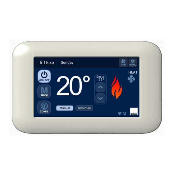
1.0 Home Screen – Key Functions Fan Select Mode Adjust Set Digital Temperature Clock Menu – Display Diagram 1: Heating Home Screen Options or Settings Mode Indicator Power Fan Status Indoor Indicator Temperature Flame System Mode Symbol (HEAT/COOL/EVAP) Zones Where Fitted * * Active with MTSP &... -
Page 6: Brivis Touch Controller Installation
To connect the Brivis appliance to the Brivis Touch: 1. Determine location of the Brivis Touch. The Brivis Touch Controller is connected to a compatible Brivis 2. Determine location of the Interface Module. appliance through the Interface Module. A 20m, four core, Power 3. -
Page 7: Location Of The Interface Module
The Interface Module shall be located within 1.5m of a 10 Amp Interface Module. 240 volt fixed switched socket outlet. The Brivis Touch shall be 2. Draw the loom from the wall cavity and feed through the within 20m of the Interface Module. -
Page 8: Install Interface Module
The Interface Module facilitates communication between the Male Clips Brivis Touch and the Brivis appliance(s) through the P&C Loom, and is capable of connecting up to four Brivis Touch units. The Interface Module requires a 12VDC power supply from the Power Transformer. -
Page 9: Connection Of Interface Module To P&C Loom
Interface Module through any of the four ports, refer to outlet. Diagram 10. 3. Distance from Interface Module to Brivis Touch shall be no more than 20m. Diagram 10: Connection of Interface Module to P&C Loom 4. Mount with supplied screws as shown in Diagram 9. -
Page 10: Connection Of Interface Module To Appliance
Brivis Appliance control wires TW1 & TW2. When connecting to an appliance, use only the first Note: When there is more than one Brivis appliance connected to set (Set 1) of two terminals or the second set (Set 2). -
Page 11: Set Day/Time
Set the correct day and time on the assigned Brivis Touch Master Controller and then press ‘Done’. For all other Brivis Touch Controllers press ‘Done’ as they will need to be converted to a SLAVE Controllers. -
Page 12: Installer Setup
Note: If multiple Brivis Touch Controllers are installed, only the When accessing the CUSTOM SETUP screen through the Master Master Controller has the ability to set the day and time. The Master Brivis Touch Controller the following options may be available, Controller can be identified by the letter "M"... -
Page 13: Reset Networker Id
When accessing the CUSTOM SETUP screen through a Slave Brivis Touch Controller the following option will be available. Diagram 18: Confirmation to prompt ID change 1. Reset the identification of the Brivis Touch Controller, refer Diagram 17. Diagram 17: Slave Brivis Touch INSTALLER SETUP Diagram 19: Set Networker Address 3.4 Reset Networker ID... -
Page 14: Networker Parameters
- MTSP parameters for Add-On Cooling and Heating systems. only requirement is to install the appliance(s), turn system power ON, set the day and time on the Brivis Touch Controller and Refer to the appendix for a detailed list of the available Master press the ON/OFF button to start the system. -
Page 15: System With Zones (Inc. Brivis Zoneplus)
- One Brivis Gas Ducted Heater 3.11 Service Notification Message - One Brivis Gas Ducted Heater + one Evaporative Cooler When the operating hours logged for an appliance exceeds the - One Brivis Gas Ducted Heater + one Add-On predetermined period, the Brivis Touch Controller displays the... -
Page 16: Outdoor Temperature Sensor (Optional)
Diagram 22: Fan run hour limit Diagram 23: NT-1 4.0 Product and Warranty Registration Brivis recommends the registration of all products to ensure The owner can book a service call or clear the spanner icon efficient product support if and when required. Please inform the notification by pressing the “Clear”... -
Page 17: Troubleshooting
6.0 Troubleshooting The Brivis Touch Controller comes with in-built diagnostics to assist in determining the cause of a fault With some faults the system will attempt to automatically restart, often several times Critical faults, where the equipment cannot automatically restart, will require a service call ... -
Page 18: Appendix
7.0 Appendix Table 2: Master Controller Parameters Parameter ID Installer Parameter Description Installer Parameter Please record Number the values you Value Settings Value have set (default) Master = 1; Slave ≥ 2 n01 ID00:0 Networker Address or Number n01 ID01:1 Refrig Common Zone - Enable Refrig/Heater ID No. - Page 19 Table 2: Master Controller Parameters Cont’d Parameter ID Please record Installer Parameter Number and Installer Parameter Description the values you Value Settings Value have set (default) n01 ID23:0 Heating Zone C - Unit Heater ID No. n01 ID24:3 Heating Zone C - Relay Relay No.
- Page 20 Fax: +64(04) 920 1681 www.warmair.co.nz © Brivis Climate Systems Pty. Ltd. 2016. All rights reserved. No part of these documents may be used in any way or form without prior written consent from Brivis Climate Systems Pty Ltd. Part Number: B063217 February 2016...
Need help?
Do you have a question about the B063047 and is the answer not in the manual?
Questions and answers