Advertisement
Quick Links
Advertisement

Subscribe to Our Youtube Channel
Related Manuals for Secure SSR 302


Summary of Contents for Secure SSR 302
- Page 1 SSR 302 User and Installation Instructions Two channel 3 Amp switch (Rx) – Z-Wave...
- Page 2 ‘Thermostat Mode SET’ commands or ‘Binary Switch SET’ commands. This SSR 302 will act as a repeater once added into the Z-Wave network, providing an alternative communication route for units which otherwise would not be within communication distance of each other.
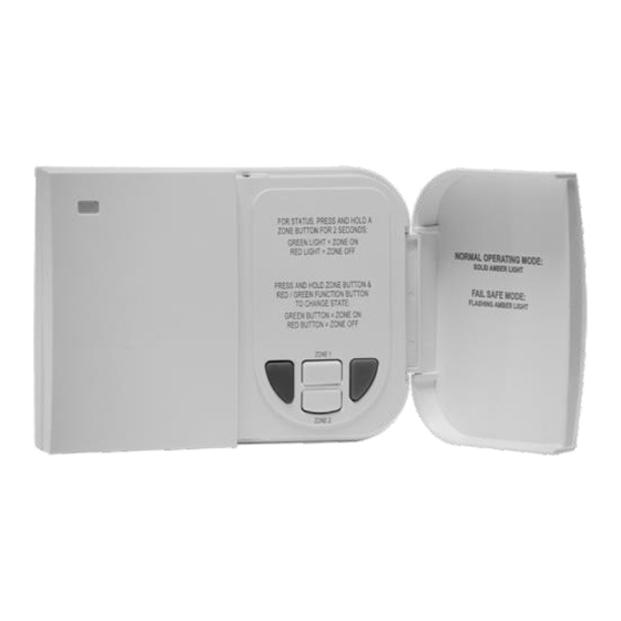
- Page 3 Receiver status LED The unit has 4 buttons and 1 LED status indicator that are used in combination as follows: Status LED White buttons Red override OFF Green override OFF LED indication Unit mode Button usage Flashing Red Unit is currently Red and Green - Switches removed from a channel relay OFF or ON...
- Page 4 Solid Green Unit is reflecting the Top White button held for Zone 1 status of the Zone or Bottom White button held for selected depending Zone 2. on the white button Red and Green - switches Zone pressed. Solid Green relay off or on respectively.
-
Page 5: Fitting The Receiver
Mark the fixing positions through the slots in the backplate, drill and plug the wall, then secure the plate in position. The slots in the backplate will compensate for any misalignment of the fixings. -
Page 6: Electrical Connections
Wiring Box Mounting The receiver backplate may be fitted directly onto a single gang steel flush wiring box complying to BS4662 using two M3.5 screws. The receiver is suitable for mounting on a flat surface only. It must not be positioned on an unearthed metal surface. - Page 7 Internal Wiring Diagram The SSR 302 has an integral connection which makes it suitable for mains Internal Electronics voltage applications only. No additional linking required between ZONE 2 ZONE 1 ZONE 2 ZONE 1 terminals. Please ensure that all installations comply with the current regulations.
- Page 8 To add the unit to a 3rd party controller follow these steps, also known as ‘inclusion’ in Z-Wave terminology. Ensure the LED is flashing RED on the SSR 302, if not follow the steps in ‘Remove from a network’ first. ...
- Page 9 Node Information Frame - NIF Pressing and holding the two white buttons for 1 second will trigger the SSR 302 to issue a Node Information Frame and enter Classic learn mode for 2s and then in NWI(Network Wide Inclusion) learn mode. This is useful...
- Page 10 Device Specific Get Device Specific Report Manufacturer ID = 0x0059 Product Type ID = 0x0003 Product ID = 0x0006 (SSR 302) Device ID Type 0 and 1 for serial number (Data format Binary, length 4 Bytes) Version (V2) Report Version Command Class Get...
- Page 11 Product supports one group (Lifeline) and have a maximum of 4 node. No current active group. Multi Channel Association Set Multi Channel Association (V3) Multi Channel Association Get Multi Channel Association Report Multi Channel Association Remove Multi Channel Association Supported Groupings Get Multi Channel Association Supported Groupings Report...
- Page 12 Only ‘Idle Mode’ and ‘Heat Mode’ are supported within this command class, which can either set or read. The SSR 302 has a failsafe mode where by the relay is turned off if another Thermostat Mode SET command has not been received within 60 minutes.
-
Page 13: Device Reset
This command is used to independently access the two channels available on the SSR 302. Product has 2 identical, non-dynamic end points with no aggregated endpoints. Each endpoint capability reports: Generic Device Class: SWITCH BINARY Specific Device Class: POWER SWITCH BINARY... - Page 14 SSR 302 (receiver) specification Electrical Purpose of control Electronic multipurpose control (Independently Mounted) Contact rating 3(1)A, 230V AC Control type Micro-Interruption Supply 230V AC, 50Hz only Control action Type 1B Operating time Limitation Intermittent Software class Class A Receiver category...
- Page 15 European Head Office Secure Controls (UK) Ltd. South Bristol Business Park Roman Farm Road Bristol, BS4 1UP, UK e: info@securetogether.com www.securetogether.com European Sales Office CEWE Instrument AB Box 1006, 611 31 Nyköping t: +46 8 600 80 60 e: info@securetogether.com www.securetogether.com...
- Page 16 Secure Meters Ltd Pratap Nagar Industrial Area Udaipur 313003 India p: +91 294 2492 300-05 f: +91 294 2492 310 e: mktg@securetogether.com www.securetogether.com Elegant Metering Solutions FZE 4EA 326, P.O. Box 54857 Dubai Airport Free Zone Dubai, UAE p: +971 50 6575166 f: +971 04 204 5619 e: emsfze@emsdxb.ae...
Need help?
Do you have a question about the SSR 302 and is the answer not in the manual?
Questions and answers