Advertisement
Table of Contents
- 1 SSR303 Receiver Unit
- 2 Installing the Receiver
- 3 Installing the SSR303
- 4 Direct Wall Mounting
- 5 Wall Box Mounting
- 6 Electrical Connections
- 7 SSR303 Internal Wiring Diagram
- 8 Receiver Status LED
- 9 Connecting to a Third Party Controller
- 10 Disconnecting from a Network
- 11 Node Information Frame - NIF
- 12 Z-Wave Repeater
- 13 Supported Device and Command Classes
- 14 Receiver Specification SSR303
- Download this manual
Advertisement
Table of Contents

Subscribe to Our Youtube Channel
Related Manuals for Secure SSR303

Summary of Contents for Secure SSR303
- Page 1 SSR303 One Channel 3 Amp Switch (Rx Only) - Z-Wave User and Installation Instructions...
- Page 3 ‘Thermostat Mode SET’ commands or ‘Binary Switch SET’ commands. This SSR303 will act as a repeater once included into the Z-wave network, providing an alternative communication route for units which otherwise would not be within communication distance of each other.
- Page 4 On and Off using the On/Off buttons on the SSR303 receiver as a local override. If the override is used to override the system when it is...
- Page 5 SSR303 is re-sealed to prevent damage from dust, debris etc. The wall plate should be fitted with the retaining screws located at the bottom and in a position which allows a total clearance of at least 50mm around the SSR303 receiver.
- Page 6 Direct Wall Mounting Offer the plate to the wall in the position where the SSR303 is to be mounted and mark the fixing positions through the slots in the wall plate. Drill and plug the wall, then secure the plate into position. The slots in the wall plate will compensate for any misalignment of the fixings.
- Page 7 Electrical Connections All necessary electrical connections should now be made. Flush wiring can enter from the rear through the aperture in the backplate. The mains supply terminals are intended to be connected to the supply by means of fixed wiring. The receiver is mains powered and requires a 3 Amp fused spur.
- Page 8 SSR303 internal wiring diagram The receiver has voltage Free contacts. Fit link between L & 2 for mains voltage applications Please ensure that all installations comply with current IEE regulations.
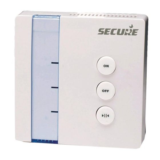
- Page 9 Receiver status LED This unit has three buttons and three LEDs - ON, OFF and Network (from top to bottom) that are used as follows:- LED indication Unit mode Button usage Solid Off LED Unit is currently Off and On - No Flashing Network LED excluded from the function...
- Page 10 Receiver status LED continued.. LED indication Unit mode Button usage Solid ON LED Unit is reflecting the Off and On - switches status of the relay channel relay off or on output. The output is respectively. Network - Network function Solid OFF LED Unit is in failsafe mode Off and On - No...
- Page 11 To connect the unit to a 3rd party controller follow these steps, also known as ‘inclusion’ in Z-wave terminology. - Ensure the network LED is flashing on the SSR303, if not follow the steps in ‘Disconnecting from a network’ first.
- Page 12 ‘exclusion’ in, Z-wave, terminology - Put the 3rd party controller into exclusion mode. - Press and hold the network button on the SSR303. - The SSR303 has been excluded from the network when the Network LED starts flashing.
- Page 13 This can be done at any time but will not provide any indication to the operator. Z-wave Repeater This SSR303 will act as a repeater once included into the Z-wave network, providing an alternative communication route for units which otherwise would...
- Page 14 Only ‘Off Mode’ and ‘Heat Mode’ are Command Class supported within this command class, which can either set or read. The SSR303 has a failsafe mode where by the relay is turned off if a command has not been received within 60 minutes.
- Page 15 Multi Channel This command is used to independently Command Class (Ver 2) access the two channels available on the SSR303. Basic Command Class The Basic Command Class has been mapped to the Thermostat Mode Command Class as follows:...
- Page 16 Receiver specification SSR303 Power Supply 230V AC 50Hz Contact type Micro disconnection Voltage free Contact rating 3 (1) Amps 230v AC Operating temperature Range 0-40°C Double Insulated Rated Impulse voltage Cat 1 – 1500v Pollution control Degree2 Enclosure protection IP30...
Need help?
Do you have a question about the SSR303 and is the answer not in the manual?
Questions and answers