Advertisement
Quick Links
léÉê~íáçåI=fåëí~ää~íáçå=~åÇ=pÉêîáÅÉ=j~åì~ä
lêáÖáå~ä=açÅìãÉåí~íáçå=L=hÉÉé=Ñçê=cìíìêÉ=oÉÑÉêÉåÅÉ
k^sfd^q u jh N
aáÖáí~ä=dóêçÅçãé~ëë=póëíÉãë
qóéÉ=QVNQJ`^I=píçÅâ=kçK=TQUMT=~åÇ=qóéÉ=QVNQJ``I=píçÅâ=kçK=TQUNN
MQVNQJMNOUJMN
MRSPQPLcI=PM=pÉé=OMNQ
kçêíÜêçé=dêìãã~å=péÉêêó=j~êáåÉ=_KsK=EoÉéêÉëÉåí~íáîÉ=lÑÑáÅÉF
tçäíã~åëíêK=NV=√=aJOMMVT=√=e~ãÄìêÖI=dÉêã~åó
qÉäKW HQVJQMJOVV MMJM=√=c~ñW HQVJQMJOVV MMJNQS=√=bJã~áäW ëÉêîáÅÉKÇÉ]ëéÉêêóKåÖÅKÅçã
Advertisement

Related Manuals for Sperry Marine NAVIGAT X MK1


Summary of Contents for Sperry Marine NAVIGAT X MK1
- Page 1 léÉê~íáçåI=fåëí~ää~íáçå=~åÇ=pÉêîáÅÉ=j~åì~ä lêáÖáå~ä=açÅìãÉåí~íáçå=L=hÉÉé=Ñçê=cìíìêÉ=oÉÑÉêÉåÅÉ k^sfd^q u jh N aáÖáí~ä=dóêçÅçãé~ëë=póëíÉãë qóéÉ=QVNQJ`^I=píçÅâ=kçK=TQUMT=~åÇ=qóéÉ=QVNQJ``I=píçÅâ=kçK=TQUNN MQVNQJMNOUJMN MRSPQPLcI=PM=pÉé=OMNQ kçêíÜêçé=dêìãã~å=péÉêêó=j~êáåÉ=_KsK=EoÉéêÉëÉåí~íáîÉ=lÑÑáÅÉF tçäíã~åëíêK=NV=√=aJOMMVT=√=e~ãÄìêÖI=dÉêã~åó qÉäKW HQVJQMJOVV MMJM=√=c~ñW HQVJQMJOVV MMJNQS=√=bJã~áäW ëÉêîáÅÉKÇÉ]ëéÉêêóKåÖÅKÅçã...
- Page 2 © 2014 Northrop Grumman Sperry Marine B.V. This document and the information herein is the intellectual property of Northrop Grumman Sperry Marine B.V. [NGSM BV] and it’s associate companies and may not be copied, reproduced or translated without the express permission of NGSM BV.
- Page 3 k^sfd^q u jh N MRSPQPLc `çåíÉåíë p~ÑÉíó=fåëíêìÅíáçåë p~ÑÉíó=kçíáÅÉ=`çåîÉåíáçåëKKKKKKKKKKKKKKKKKKKKKKKKKKKKKKKKKKKKKKKKKKKKKKKKKKKKKKKKKKKKKKKKKKKKKKKK îáá dÉåÉê~ä=p~ÑÉíó=fåÑçêã~íáçå=Ñçê=íÜÉ=léÉê~íçê KKKKKKKKKKKKKKKKKKKKKKKKKKKKKKKKKKKKKKKKK îááá dÉåÉê~ä=p~ÑÉíó=fåÑçêã~íáçå=Ñçê=pÉêîáÅÉ=mÉêëçååÉäKKKKKKKKKKKKKKKKKKKKKKKKKKKKKKKKK ñááá `Ü~éíÉê=NW fåíêçÇìÅíáçå póëíÉã=aÉëÅêáéíáçåKKKKKKKKKKKKKKKKKKKKKKKKKKKKKKKKKKKKKKKKKKKKKKKKKKKKKKKKKKKKKKKKKKKKKKKKKKKKKKKKKKK NJN fåíÉåÇÉÇ=rëÉ KKKKKKKKKKKKKKKKKKKKKKKKKKKKKKKKKKKKKKKKKKKKKKKKKKKKKKKKKKKKKKKKKKKKKKKKKKKKKKKKKKKKKKKKKKKKKKKNJN kçí=fåíÉåÇÉÇ=rëÉKKKKKKKKKKKKKKKKKKKKKKKKKKKKKKKKKKKKKKKKKKKKKKKKKKKKKKKKKKKKKKKKKKKKKKKKKKKKKKKKKKKKKKKKKNJN póëíÉã=lîÉêîáÉï=~åÇ=j~áå=`çãéçåÉåíë KKKKKKKKKKKKKKKKKKKKKKKKKKKKKKKKKKKKKKKKKKKKKK NJO i~ÄÉä=~åÇ=íóéÉ=ä~ÄÉä KKKKKKKKKKKKKKKKKKKKKKKKKKKKKKKKKKKKKKKKKKKKKKKKKKKKKKKKKKKKKKKKKKKKKKKKKKKKKKKKKKKKKNJP j~áå=ÅçãéçåÉåíë KKKKKKKKKKKKKKKKKKKKKKKKKKKKKKKKKKKKKKKKKKKKKKKKKKKKKKKKKKKKKKKKKKKKKKKKKKKKKKKKKKKKKKKKNJQ aÉëáÖå=~åÇ=j~áå=cÉ~íìêÉëKKKKKKKKKKKKKKKKKKKKKKKKKKKKKKKKKKKKKKKKKKKKKKKKKKKKKKKKKKKKKKKKKKKKKKKK NJS léÉê~íáåÖ=mêáåÅáéäÉ KKKKKKKKKKKKKKKKKKKKKKKKKKKKKKKKKKKKKKKKKKKKKKKKKKKKKKKKKKKKKKKKKKKKKKKKKKKKKKKKKKK NJT eÉ~ÇáåÖ=bêêçê=i~íáíìÇÉ=`çêêÉä~íáçå KKKKKKKKKKKKKKKKKKKKKKKKKKKKKKKKKKKKKKKKKKKKKKKKKKKKKKKKKKKKKKKNJV bñ~ãéäÉ=póëíÉã=`çåÑáÖìê~íáçåë KKKKKKKKKKKKKKKKKKKKKKKKKKKKKKKKKKKKKKKKKKKKKKKKKKKKKKKKKKKKNJNN pí~åÇ~äçåÉ=dóêçÅçãé~ëëLqj`=póëíÉã KKKKKKKKKKKKKKKKKKKKKKKKKKKKKKKKKKKKKKKKKKKKKKKKKKKK NJNN aì~ä=k^sfd^q u jh N=dóêçÅçãé~ëëLqj`=póëíÉã...
- Page 4 MRSPQPLc k^sfd^q u jh N pÉäÉÅíáåÖ=m~ê~ãÉíÉê=pÉííáåÖë KKKKKKKKKKKKKKKKKKKKKKKKKKKKKKKKKKKKKKKKKKKKKKKKKKKKKKKKKKKKKKKKKKKKKK OJU bÇáíáåÖ=m~ê~ãÉíÉê=s~äìÉë KKKKKKKKKKKKKKKKKKKKKKKKKKKKKKKKKKKKKKKKKKKKKKKKKKKKKKKKKKKKKKKKKKKKKKKKKKKK OJU pÉäÉÅíáåÖ=~=aáëéä~ó=a~í~=m~ÖÉKKKKKKKKKKKKKKKKKKKKKKKKKKKKKKKKKKKKKKKKKKKKKKKKKKKKKKKKKKKKKKKKKK OJV OKNM j~åì~ä=pÉííáåÖë=jÉåì KKKKKKKKKKKKKKKKKKKKKKKKKKKKKKKKKKKKKKKKKKKKKKKKKKKKKKKKKKKKKKKKKKKKKKKKKKK OJNM `~éíáçå=Ñçê=pÉäÉÅíáåÖ=~åÇ=bÇáíáåÖ KKKKKKKKKKKKKKKKKKKKKKKKKKKKKKKKKKKKKKKKKKKKKKKKKKKKKKKKKKKKKK OJNM j~åì~ä=pÉííáåÖë=Ó=lîÉêîáÉï KKKKKKKKKKKKKKKKKKKKKKKKKKKKKKKKKKKKKKKKKKKKKKKKKKKKKKKKKKKKKKKKKKKKKKOJNN j~åì~ä=pÉííáåÖë=Ó=m~ê~ãÉíÉêë KKKKKKKKKKKKKKKKKKKKKKKKKKKKKKKKKKKKKKKKKKKKKKKKKKKKKKKKKKKKKKKKKK OJNP OKNN rëÉê=pÉíìé KKKKKKKKKKKKKKKKKKKKKKKKKKKKKKKKKKKKKKKKKKKKKKKKKKKKKKKKKKKKKKKKKKKKKKKKKKKKKKKKKKKKKKKKKKKKKKK OJNT rëÉê=pÉíìé=Ó=lîÉêîáÉï KKKKKKKKKKKKKKKKKKKKKKKKKKKKKKKKKKKKKKKKKKKKKKKKKKKKKKKKKKKKKKKKKKKKKKKKKKKKK OJNT rëÉê=pÉíìé=Ó=m~ê~ãÉíÉêë KKKKKKKKKKKKKKKKKKKKKKKKKKKKKKKKKKKKKKKKKKKKKKKKKKKKKKKKKKKKKKKKKKKKKKKKKK OJNU `Ü~éíÉê=PW bêêçêë=~åÇ=^ä~êãë ^ä~êã=fåÇáÅ~íáçå KKKKKKKKKKKKKKKKKKKKKKKKKKKKKKKKKKKKKKKKKKKKKKKKKKKKKKKKKKKKKKKKKKKKKKKKKKKKKKKKKKKKKKKK PJN ^ìÇáÄäÉ=^ä~êã=fåÇáÅ~íáçåKKKKKKKKKKKKKKKKKKKKKKKKKKKKKKKKKKKKKKKKKKKKKKKKKKKKKKKKKKKKKKKKKKKKKKKKKKKKKK PJN sáëì~ä=^ä~êã=fåÇáÅ~íáçå...
- Page 5 k^sfd^q u jh N MRSPQPLc `Ü~éíÉê=TW póëíÉã=fåëí~ää~íáçå fåëí~ääáåÖ=oÉÅçããÉåÇ~íáçåë KKKKKKKKKKKKKKKKKKKKKKKKKKKKKKKKKKKKKKKKKKKKKKKKKKKKKKKKKKKKKKKKKKK TJN mä~ÅÉ=çÑ=fåëí~ää~íáçå KKKKKKKKKKKKKKKKKKKKKKKKKKKKKKKKKKKKKKKKKKKKKKKKKKKKKKKKKKKKKKKKKKKKKKKKKKKKKKKKKKKKK TJN sÉåíáä~íáçå=L=qÉãéÉê~íìêÉ KKKKKKKKKKKKKKKKKKKKKKKKKKKKKKKKKKKKKKKKKKKKKKKKKKKKKKKKKKKKKKKKKKKKKKKKKKKK TJN bäÉÅíêçã~ÖåÉíáÅ=fåíÉêÑÉêÉåÅÉKKKKKKKKKKKKKKKKKKKKKKKKKKKKKKKKKKKKKKKKKKKKKKKKKKKKKKKKKKKKKKKKKKKKKK TJN sáÄê~íáçå KKKKKKKKKKKKKKKKKKKKKKKKKKKKKKKKKKKKKKKKKKKKKKKKKKKKKKKKKKKKKKKKKKKKKKKKKKKKKKKKKKKKKKKKKKKKKKKKKKKKKK TJO jÉÅÜ~åáÅ~ä=fåëí~ää~íáçåKKKKKKKKKKKKKKKKKKKKKKKKKKKKKKKKKKKKKKKKKKKKKKKKKKKKKKKKKKKKKKKKKKKKKKKKKKKKK TJP qê~åëéçêíáåÖ=íÜÉ=`çãé~ëë=eçìëáåÖ KKKKKKKKKKKKKKKKKKKKKKKKKKKKKKKKKKKKKKKKKKKKKKKKKKKKKKKKKKKK TJP fåëí~ääáåÖ=íÜÉ=`çãé~ëë=eçìëáåÖ KKKKKKKKKKKKKKKKKKKKKKKKKKKKKKKKKKKKKKKKKKKKKKKKKKKKKKKKKKKKKKKKK TJP bäÉÅíêáÅ~ä=fåëí~ää~íáçå KKKKKKKKKKKKKKKKKKKKKKKKKKKKKKKKKKKKKKKKKKKKKKKKKKKKKKKKKKKKKKKKKKKKKKKKKKKKKKKK TJQ ^`=pìééäó=mçïÉê=`çåÑáÖìê~íáçå KKKKKKKKKKKKKKKKKKKKKKKKKKKKKKKKKKKKKKKKKKKKKKKKKKKKKKKKKKKKKKKKKK TJQ táêáåÖ=ré=íÜÉ=póëíÉã KKKKKKKKKKKKKKKKKKKKKKKKKKKKKKKKKKKKKKKKKKKKKKKKKKKKKKKKKKKKKKKKKKKKKKKKKKKKKKKKK TJR dóêçëéÜÉêÉ=fåëí~ää~íáçå KKKKKKKKKKKKKKKKKKKKKKKKKKKKKKKKKKKKKKKKKKKKKKKKKKKKKKKKKKKKKKKKKKKKKKKKKKKK TJS fåáíá~ä=póëíÉã=`çåÑáÖìê~íáçå...
- Page 6 MRSPQPLc k^sfd^q u jh N `Ü~éíÉê=NMW `çêêÉÅíáîÉ=j~áåíÉå~åÅÉ NMKN bñÅÜ~åÖáåÖ=íÜÉ=póëíÉã=pçÑíï~êÉ KKKKKKKKKKKKKKKKKKKKKKKKKKKKKKKKKKKKKKKKKKKKKKKKKKKKKKKKK NMJN NMKO oÉéä~ÅáåÖ=pçÅâÉíÉÇ=f`ëKKKKKKKKKKKKKKKKKKKKKKKKKKKKKKKKKKKKKKKKKKKKKKKKKKKKKKKKKKKKKKKKKKKKKKKKKKK NMJO `Ü~éíÉê=NNW k^sfd^q u=jhN=pé~êÉ=m~êíë NNKN fääìëíê~íÉÇ=m~êíë=iáëí=EfmiF=lîÉêîáÉï KKKKKKKKKKKKKKKKKKKKKKKKKKKKKKKKKKKKKKKKKKKKKKKKKKKKKK NNJN ^ÄÄêÉîá~íáçåë ^ééÉåÇáñ pÉíìé=~åÇ=`çåÑáÖìê~íáçå=q~ÄäÉë aê~ïáåÖë îá...
- Page 7 k^sfd^q u jh N MRSPQPLc p~ÑÉíó=fåëíêìÅíáçåë p~ÑÉíó=kçíáÅÉ=`çåîÉåíáçåë The following safety notice conventions are followed throughout this manual: A a~åÖÉê notice begins with the named type of a^kdbo danger and contains an operating or mainte- nance procedure, practice, condition, statement, etc., which, if not strictly observed, ïáää=êÉëìäí=áå= áåàìêó=çê=ÇÉ~íÜ=çÑ=éÉêëçååÉäK A t~êåáåÖ...
- Page 8 MRSPQPLc k^sfd^q u jh N dÉåÉê~ä=p~ÑÉíó=fåÑçêã~íáçå=Ñçê=íÜÉ=léÉê~íçê t^okfkd oáëâ=çÑ=ÇÉîá~íáçå kÉîÉê=êÉäó=çå=çåÉ=ÜÉ~ÇáåÖ=ëçìêÅÉ=~äçåÉ=íç=å~îáÖ~íÉ=~=îÉëëÉäK ^äï~óë=ÅçåÑáêã=íÜÉ=éä~ìëáÄáäáíó=çÑ=íÜÉ=k^sfd^q u jh N=ÜÉ~ÇáåÖ=~åÇ=íÜÉ= ëéÉÉÇ=~åÇ=éçëáíáçå=áåéìí=Ç~í~=~Ö~áåëí=~ää=~î~áä~ÄäÉ=~áÇë=íç=å~îáÖ~íáçåK t^okfkd iáãáíÉÇ=ÜÉ~ÇáåÖ=Ç~í~=~ÅÅìê~Åó=ÇìêáåÖ=ëÉííäáåÖ=íáãÉ ^ÑíÉê=~=éçïÉêJìé=Ñêçã=ÅçäÇI=íÜÉ=k^sfd^q u jh N=êÉèìáêÉë=~=ëÉííäáåÖ=íáãÉ= çÑ=íÜêÉÉ=Üçìêë=ÄÉÑçêÉ=êÉäá~ÄäÉ=ÜÉ~ÇáåÖ=Ç~í~=áë=~î~áä~ÄäÉK mçïÉê=ìé=íÜÉ=ëóëíÉã=~í=äÉ~ëí=íÜêÉÉ=Üçìêë=ÄÉÑçêÉ=äÉ~îáåÖ=Ü~êÄçìêK mçïÉê=Ççïå=íÜÉ=ëóëíÉã=ÇìêáåÖ=äçåÖ=ÇçÅâáåÖ=éÉêáçÇë=çåäóK j~âÉ=ëìêÉ=íÜ~í=íÜÉ=k^sfd^q u jh N=Ü~ë=ëÉííäÉÇ=ÄÉÑçêÉ=ìëáåÖ=áíë=ÜÉ~ÇáåÖ= ~ë=íÜÉ=êÉÑÉêÉåÅÉ=Ñçê=ÜÉ~ÇáåÖ=Åçåíêçä=ëóëíÉãëI=o^a^oI=b`afpI=ÉíÅK ^=ã~ÖåÉíáÅ=Åçãé~ëë=ÜÉ~ÇáåÖ=ëçìêÅÉ=ëÜçìäÇ=ÄÉ=ëÉäÉÅíÉÇ=~ë=êÉÑÉêÉåÅÉ= çåäó=áå=Å~ëÉ=çÑ=Ñ~áäìêÉ=çÑ=íÜÉ=ÖóêçÅçãé~ëëEÉëFK t^okfkd oáëâ=çÑ=ãáëìë~ÖÉ _ÉÑçêÉ=ìëáåÖ=íÜÉ=k^sfd^q u jh NI=çéÉê~íçêë=ãìëí=ÄÉ=~ééêçéêá~íÉäó= íê~áåÉÇ=~åÇ=Ñ~ãáäá~ê=ïáíÜ=~ää=çéÉê~íáåÖ=éêçÅÉÇìêÉë=~åÇ=ë~ÑÉíó=áåëíêìÅJ íáçåë=Åçåí~áåÉÇ=áå=íÜáë=ã~åì~äK=qÜÉ=ã~åì~ä=áë=íç=ÄÉ=ÅçãéäÉíÉäó=êÉ~Ç= ÄÉÑçêÉ=íÜÉ=Ñáêëí=ìë~ÖÉ=çÑ=íÜÉ=k^sfd^q u jh NK hÉÉé=íÜáë=ã~åì~ä=ÇìêáåÖ=íÜÉ=ÉåíáêÉ=ëÉêîáÅÉ=äáÑÉ=çÑ=íÜÉ=éêçÇìÅí=~åÇ=~äï~óë= Ü~îÉ=áí=êÉ~Çáäó=~î~áä~ÄäÉ=áå=~=åÉ~êÄó=äçÅ~íáçå=Ñçê=êÉÑÉêÉåÅÉK `^rqflk...
- Page 9 k^sfd^q u jh N MRSPQPLc `^rqflk Risk of damage through overheating A polluted or clogged air inlet grill located at the back side of the compass housing will decrease the functionality of the cooling fan and cause over- heating of the gyrocompass. Always maintain the required distances around the compass housing to enable sufficient air supply and full cooling fan functionality.
- Page 10 If after a time period of around 45 minutes after the second power-up cycle the gyrosphere current has still not dropped below 320 mA, the gyrosphere may not be in operable working condition. Contact the Sperry Marine Service for advice. `^rqflk Risk of misleading gyrosphere data / operating values The temperature and gyrosphere current values are indicated as reading values at the CDU only.
- Page 11 A shut down of the NAVIGAT X MK 1 system for good reason is only pos- sible when the ship is NOT navigating. Sperry Marine requires to NOT shut down the NAVIGAT X MK 1 system kçíÉ as long as the vessel is navigating, even when operating in polar waters with possible unstable/unreliable heading.
- Page 12 Sperry Marine Service: In case of service refer to www.sperrymarine.com/offices for a list of all Sperry Marine Offices and Service Agents worldwide. ñáá p~ÑÉíó=fåëíêìÅíáçåë...
- Page 13 k^sfd^q u jh N MRSPQPLc dÉåÉê~ä=p~ÑÉíó=fåÑçêã~íáçå=Ñçê=pÉêîáÅÉ=mÉêëçååÉä a^kdbo iáÑÉ=Ç~åÖÉê=íÜêçìÖÜ=ÉäÉÅíêáÅ~ä=ëÜçÅâ tÜÉå=íÜÉ=Åçãé~ëë=áë=ÉåÉêÖáòÉÇI=íÜÉ=ÖóêçëéÜÉêÉ=çéÉê~íáåÖ=îçäí~ÖÉ=çÑ= NMM=s^`=]=PPT=eò=áë=éêÉëÉåí=çå=íÜÉ=ã~ëíÉê=m`_I=íÜÉ=ÖóêçëéÜÉêÉ=ëìééäó= äáåÉëI=~åÇ=~Åêçëë=íÜÉ=ÖóêçëéÜÉêÉ=Åçåí~ÅíëK= tÜÉå=íÜÉ=^`=ã~áå=ëìééäó=áë=ëïáíÅÜÉÇ=çåI=Ü~ò~êÇçìë=äáÑÉ=îçäí~ÖÉë=~êÉ= éêÉëÉåí=~í=íÜÉ=äáåÉ=ÑáäíÉê=~åÇ=íÜÉ=éçïÉê=íê~åëÑçêãÉêÛë=íÉêãáå~äëK j~âÉ=ëìêÉ=íÜ~í=íÜÉ=ã~áå=~åÇ=Ä~Åâìé=éçïÉê=ëìééäáÉë=çÑ=íÜÉ=Åçãé~ëë=~êÉ= ~äï~óë=ëïáíÅÜÉÇ=çÑÑ=~åÇ=ë~ÑÉÖì~êÇÉÇ=~Ö~áåëí=~ÅÅáÇÉåí~ä=ëïáíÅÜáåÖJçå= ÄÉÑçêÉ=ìåÇÉêí~âáåÖ=~åó=êÉãçî~ä=çê=áåëí~ää~íáçå=éêçÅÉÇìêÉë=çÑ=íÜÉ=ÖóêçJ ëéÜÉêÉ=Åçåí~áåÉêK a^kdbo iáÑÉ=Ç~åÖÉê=íÜêçìÖÜ=ÉäÉÅíêáÅ~ä=ëÜçÅâ tÜÉå=íÜÉ=Åçãé~ëë=áë=ÉåÉêÖáòÉÇI=íÜÉ=ÖóêçëéÜÉêÉ=çéÉê~íáåÖ=îçäí~ÖÉ=çÑ= NMM=s^`=]=PPT=eò=áë=éêÉëÉåí=çå=íÜÉ=ã~ëíÉê=m`_I=íÜÉ=ÖóêçëéÜÉêÉ=ëìééäó= äáåÉë=~åÇ=~Åêçëë=íÜÉ=ÖóêçëéÜÉêÉ=Åçåí~ÅíëK= tÜÉå=íÜÉ=^`=ã~áå=ëìééäó=áë=ëïáíÅÜÉÇ=çåI=Ü~ò~êÇçìë=äáÑÉ=îçäí~ÖÉë=~êÉ= éêÉëÉåí=~í=íÜÉ=äáåÉ=ÑáäíÉê=~åÇ=íÜÉ=éçïÉê=íê~åëÑçêãÉêÛë=íÉêãáå~äëK _É=ÉñíêÉãÉäó=Å~êÉÑìä=ïÜÉå=çéÉê~íáåÖ=íÜÉ=Åçãé~ëë=ïÜáäÉ=íÜÉ=ÜçìëáåÖ=áë= çéÉåK=kÉïÉê=íçìÅÜ=íÜÉ=ã~ëíÉê=m`_I=íÜÉ=ÅçååÉÅíáåÖ=Å~ÄäÉë=íç=íÜÉ=ÖóêçJ ëéÜÉêÉ=Åçåí~áåÉê=çê=~åó=çíÜÉê=ÅçåÇìÅíáîÉ=ÅçãéçåÉåíë=çå=íÜÉ=Åçåí~áåÉê= çê=áå=íÜÉ=Åçãé~ëë=ÜçìëáåÖK ^äï~óë=ÉñÅäìÇÉ=~åó=Åçåí~Åí=íç=ÉåÉêÖáòÉÇ=ÅçãéçåÉåíëK a^kdbo iáÑÉ=Ç~åÖÉê=íÜêçìÖÜ=ÉäÉÅíêáÅ~ä=ëÜçÅâ tÜÉå=íÜÉ=^`=ã~áå=ëìééäó=áë=ëïáíÅÜÉÇ=çåI=äáîÉ=îçäí~ÖÉë=~êÉ=éêÉëÉåí=~í=íÜÉ= äáåÉ=ÑáäíÉê=~åÇ=íÜÉ=éçïÉê=íê~åëÑçêãÉêÛë=íÉêãáå~äëK tÜÉå=íÜÉ=Åçãé~ëë=áë=ÉåÉêÖáòÉÇ=Eã~áå=~åÇLçê=Ä~Åâìé=ëìééäó=éêÉëÉåíFI= íÜÉ=ÖóêçëéÜÉêÉ=çéÉê~íáåÖ=îçäí~ÖÉ=çÑ=NMM=s^`=]=PPT=eò=áë=éêÉëÉåí=çå=íÜÉ= ã~ëíÉê=m`_I=íÜÉ=ÖóêçëéÜÉêÉ=ëìééäó=äáåÉë=~åÇ=~Åêçëë=íÜÉ=ÖóêçëéÜÉêÉ=ÅçåJ í~ÅíëK j~âÉ=ëìêÉ=íÜÉ=Åçãé~ëëD=ã~áå=~åÇ=Ä~Åâìé=éçïÉê=ëìééäáÉë=~êÉ=~äï~óë= ëïáíÅÜÉÇ=çÑÑ=~åÇ=ë~ÑÉÖì~êÇÉÇ=~Ö~áåëí=~ÅÅáÇÉåí~ä=ëïáíÅÜáåÖJçå=ïÜÉå= ÅçåÑáÖìêáåÖ=íÜÉ=ëóëíÉã=Ñçê=íÜÉ=îÉëëÉäÛë=^`=ëìééäó=îçäí~ÖÉI `^rqflk Risk of damage/destruction during transport The gyrosphere is always to be transported in its carrying box in the orig-...
- Page 14 MRSPQPLc k^sfd^q u jh N `^rqflk Risk of erroneous heading accuracy caused by vibration / resonance frequencies The NAVIGAT X MK 1 gyrocompass is a highly sensitive instrument. Resonance frequencies or vibrations caused by incorrect install position or install and environmental conditions will badly influence the heading accuracy.
- Page 15 If after a time period of around 45 minutes after the second power-up cycle the gyrosphere current has still not dropped below 320 mA, the gyrosphere may not be in operable working condition. Contact the Sperry Marine Service for advice. p~ÑÉíó=fåëíêìÅíáçåë ñî...
- Page 16 MRSPQPLc k^sfd^q u jh N A visual inspection of cables and connectors of the gyrocompass should kçíÉ be carried out regularly to detect any signs of damage or deterioration. In case a „Speed Invalid“ alarm is triggered while the vessel is not in kçíÉ...
- Page 17 k^sfd^q u jh N MRSPQPLc `Ü~éíÉê=NW fåíêçÇìÅíáçå NKN póëíÉã=aÉëÅêáéíáçå fåíÉåÇÉÇ=rëÉ The NAVIGAT X MK 1 is a digital gyrocompass system for the maritime navigation of vessels and must be operated only from appropriately trained and educated personnel familiar with all mandatory safety and operating procedures.
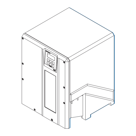
- Page 18 MRSPQPLc k^sfd^q u jh N NKO póëíÉã=lîÉêîáÉï=~åÇ=j~áå=`çãéçåÉåíë cáÖìêÉ=NJNW k^sfd^q u jh N=ÜçìëáåÖ cáÖìêÉ=NJOW `çåíêçä=~åÇ=Çáëéä~ó=ìåáí E`arF=Ñêçåí=~åÇ Ä~Åâ=îáÉï kçK fíÉã níóK USB service interface Dimmer (CDU display) póëíÉã=lîÉêîáÉï=~åÇ=j~áå=`çãéçåÉåíë...
- Page 19 k^sfd^q u jh N MRSPQPLc i~ÄÉä=~åÇ=íóéÉ=ä~ÄÉä The label at the front door shows the power-up sequence and a quick kçíÉ guide to the operation menu for a single NAVIGAT X MK 1 gyrocompass system only. cáÖìêÉ=NJPW k^sfd^q u jh N ä~ÄÉä...
- Page 20 MRSPQPLc k^sfd^q u jh N j~áå=ÅçãéçåÉåíë cáÖìêÉ=NJRW mêáåíÉÇ=`áêÅìáí=_ç~êÇ Em`_F kçK fíÉã níóK Master Printed Circuit Board (PCB) Hex head screws MK1 housing In figure 1-5 the front door is not shown for better understanding. póëíÉã=lîÉêîáÉï=~åÇ=j~áå=`çãéçåÉåíë...
- Page 21 k^sfd^q u jh N MRSPQPLc cáÖìêÉ=NJSW dóêçëéÜÉêÉ=ëìëéÉåëáçå kçK fíÉã níóK Gyrosphere suspension In figure 1-6 and 1-7 the PCB is not shown for better understanding. cáÖìêÉ=NJTW _~ëÉ=éä~íÉ=~åÇ=ÖóêçJ ëéÜÉêÉ=ëìëéÉåëáçå kçK fíÉã níóK Base plate Gyrosphere suspension Main power supply transformer (partly covered) Sticker of shaft encoder correction angle value póëíÉã=lîÉêîáÉï=~åÇ=j~áå=`çãéçåÉåíë...
- Page 22 MRSPQPLc k^sfd^q u jh N NKP aÉëáÖå=~åÇ=j~áå=cÉ~íìêÉë The NAVIGAT X MK 1 is a microprocessor controlled marine gyrocom- pass system with integrated automatic North speed error correction. The NAVIGAT X MK 1 has been type approved by Germanischer Lloyd (GL), in accordance with the Marine Equipment Directive (MED) 96/98/ EC, as amended, as gyrocompass (certificate no.
- Page 23 k^sfd^q u jh N MRSPQPLc NKQ léÉê~íáåÖ=mêáåÅáéäÉ The north-seeking element used in the NAVIGAT X MK 1 system is the gyrosphere, a hermetically sealed unit with a funnel-shaped recess, reaching from the outer skin down to its centre. Inside the gyrosphere, two mechanically linked gyroscopes are mounted with their spin axes horizontal in a carrying frame.
- Page 24 Only specially trained personnel is allowed to take care with all handling of mercury and special handling procedures must be maintained. Always keep to the current issue of the mercury handling procedures of Sperry Marine Northrop Grumman, stock no. 026150-0000-000. léÉê~íáåÖ=mêáåÅáéäÉ...
- Page 25 k^sfd^q u jh N MRSPQPLc eÉ~ÇáåÖ=bêêçê=i~íáíìÇÉ=`çêêÉä~íáçå `^rqflk Risk of unstable/unreliable heading in polar waters When operating the vessel in polar waters, the heading information of the gyrocompass may become unstable/unreliable resulting in possible deviation. For safe steering in polar waters, the heading information of the gyro- compass may therefore NOT be used for navigation and heading infor- mation of a GNSS (Global Navigation Satellite System) compass be preferred instead.
- Page 26 GNSS compass be preferred instead. Sperry Marine requires to NOT shut down the NAVIGAT X MK 1 system kçíÉ as long as the vessel is navigating, even when operating in polar waters with possible unstable/unreliable heading.
- Page 27 k^sfd^q u jh N MRSPQPLc NKR bñ~ãéäÉ=póëíÉã=`çåÑáÖìê~íáçåë pí~åÇ~äçåÉ=dóêçÅçãé~ëëLqj`=póëíÉã As a standalone system, the NAVIGAT X MK 1 provides North-speed error corrected true heading as well as rate of turn data. If a magnetic compass with fluxgate sensor, type 4863, or an electronic compass is installed, the NAVIGAT X MK 1 applies magnetic variation and distributes magnetic compass heading data to external equipment (Transmitting Magnet Compass, TMC function).
- Page 28 MRSPQPLc k^sfd^q u jh N aì~ä=k^sfd^q u jh N=dóêçÅçãé~ëëLqj`=póëíÉã The system shown in figure 1-13 below is the standard configuration for a dual NAVIGAT X MK 1 gyrocompass system. In addition to the two NAVIGAT X MK 1 gyrocompasses, this system comprises the NAVITWIN IV heading management system (HMS) and the Switch-Over Unit Type 4932.
- Page 29 k^sfd^q u jh N MRSPQPLc NKS qÉÅÜåáÅ~ä=a~í~ ^ÅÅìê~ÅáÉë heading: linear mean settle point error ≤ 0.1° x secant latitude static heading error ≤ 0.1° x secant latitude dynamic heading error* (range of operation ≤ 0.4° x secant latitude within 70° S to 70° N latitude) deviation after 3 min.
- Page 30 MRSPQPLc k^sfd^q u jh N bäÉÅíêçã~ÖåÉíáÅ=`çãé~íáÄáäáíó=Ebj`F=L=bäÉÅíêçã~ÖåÉíáÅ=fåíÉêÑÉêÉåÅÉ according to IEC 60945: minimum clearance to MF/HF transceiver 1.5 m units and their antennas. minimum clearance to high voltage power 1.5 m lines > 380 VAC of other equipment sáÄê~íáçå according to GL: „Rules for Classification and Applicable in Area A Construction, I - Ship Technology, Part 1 - Sea- classified locations...
- Page 31 NMEA 0183 / IEC 61162-1 (Heading Management System) páÖå~ä=~åÇ=pí~íìë=fåéìíë magnetic compass heading, sine, cosine and reference (ref.) fluxgate sensor voltages from Sperry Marine flux- gate sensor type 4863 speed, 200 pulse/nm connection to power ground (P.Gnd) via external contact, momentary rudder angle feedback unit 0 –...
- Page 32 MRSPQPLc k^sfd^q u jh N a~í~=lìíéìíë serial repeater outputs NMEA 0183 (12x TTL) sensor data outputs NMEA 0183 / IEC 61162-1 (4x RS-422; 3 available if AD10 output active) FAST output NMEA 0183 / IEC 61162-1 (1x RS-422) or PLATH protocol (update rate 20 Hz) SuperFAST output NMEA 0183 / IEC 61162-1...
- Page 33 Notified Body No. 0098 Germanischer Lloyd. The current issue of the detailed Marine Equipment Directive EC Declara- kçíÉ tion of Conformity of Northrop Grumman Sperry Marine B.V. Hamburg is part of the client CD stock no. 56 800. For further details please contact: Northrop Grumman Sperry Marine B.V.
- Page 34 MRSPQPLc k^sfd^q u jh N NJNU j~êáåÉ=bèìáéãÉåí=aáêÉÅíáîÉ=b`=aÉÅä~ê~íáçå=çÑ=`çåJ...
- Page 35 k^sfd^q u jh N MRSPQPLc `Ü~éíÉê=OW léÉê~íáçå OKN léÉê~íáåÖ=`çåÇáíáçåë The permitted ambient temperature for the operation of the gyrocom- pass system is between - 10° C to + 55° C. The recommended ambient temperature for highest system longevity for the operation of the gyrocompass system is around 20° C. `^rqflk Risk of damage/destruction through low temperatures The supporting fluid in the gyrosphere container will start freezing at...
- Page 36 MRSPQPLc k^sfd^q u jh N OKO aáëéä~ó=~åÇ=léÉê~íáåÖ=hÉóë `çåíêçä=~åÇ=aáëéä~ó=råáí=E`arF cáÖìêÉ=OJNW k^sfd^q u jh N Åçåíêçä=~åÇ=Çáëéä~ó=ìåáí ÿÿÿÿÿÿÿÿÿÿÿÿÿÿÿÿÿÿÿÿ ÿÿÿÿÿÿÿÿÿÿÿÿÿÿÿÿÿÿÿÿ ÿÿÿÿÿÿÿÿÿÿÿÿÿÿÿÿÿÿÿÿ ÿÿÿÿÿÿÿÿÿÿÿÿÿÿÿÿÿÿÿÿ aáëéä~ó i`a=aáëéä~óW=4x20 character text display. • In normal operational mode: shows the available heading sources and the heading difference alarm threshold. • In menu mode: displays the currently active operating menu screen.
- Page 37 k^sfd^q u jh N MRSPQPLc OKP bñíÉêå~ä=`çåíêçä=aÉîáÅÉë Depending on the installation, external devices may be present which remotely control certain functions of the NAVIGAT X MK 1: • bñíÉêå~ä=ÇÉîáÅÉW An external device may be used to select the “active” source, i.e. the heading reference to be distributed to com- pass repeaters, heading control system, RADAR, ECDIS etc.
- Page 38 MRSPQPLc k^sfd^q u jh N OKQ mçïÉêJìé=pÉèìÉåÅÉ t^okfkd iáãáíÉÇ=ÜÉ~ÇáåÖ=Ç~í~=~ÅÅìê~Åó=ÇìêáåÖ=ëÉííäáåÖ=íáãÉ ^ÑíÉê=~=éçïÉêJìé=Ñêçã=ÅçäÇI=íÜÉ=k^sfd^q u jh N=êÉèìáêÉë=~=ëÉííäáåÖ=íáãÉ= çÑ=íÜêÉÉ=Üçìêë=ÄÉÑçêÉ=êÉäá~ÄäÉ=ÜÉ~ÇáåÖ=Ç~í~=áë=~î~áä~ÄäÉK mçïÉê=ìé=íÜÉ=ëóëíÉã=~í=äÉ~ëí=íÜêÉÉ=Üçìêë=ÄÉÑçêÉ=äÉ~îáåÖ=Ü~êÄçìêK mçïÉê=Ççïå=íÜÉ=ëóëíÉã=ÇìêáåÖ=äçåÖ=ÇçÅâáåÖ=éÉêáçÇë=çåäóK j~âÉ=ëìêÉ=íÜ~í=íÜÉ=k^sfd^q u jh N=Ü~ë=ëÉííäÉÇ=ÄÉÑçêÉ=ìëáåÖ=áíë=ÜÉ~ÇáåÖ= ~ë=íÜÉ=êÉÑÉêÉåÅÉ=Ñçê=ÜÉ~ÇáåÖ=Åçåíêçä=ëóëíÉãëI=o^a^oI=b`afpI=ÉíÅK ^=ã~ÖåÉíáÅ=Åçãé~ëë=ÜÉ~ÇáåÖ=ëçìêÅÉ=ëÜçìäÇ=ÄÉ=ëÉäÉÅíÉÇ=~ë=êÉÑÉêÉåÅÉ= çåäó=áå=Å~ëÉ=çÑ=Ñ~áäìêÉ=çÑ=íÜÉ=ÖóêçÅçãé~ëëEÉëFK The NAVIGAT X MK 1 is not equipped with a power switch. The gyro- compass powers up as soon as supply power is applied. Upon power-up, the startup routine is executed: A startup screen is shown and a system SPERRY...
- Page 39 k^sfd^q u jh N MRSPQPLc OKR pÉäÉÅíáåÖ=íÜÉ=^ÅíáîÉ=eÉ~ÇáåÖ=pçìêÅÉ t^okfkd iáãáíÉÇ=ÜÉ~ÇáåÖ=Ç~í~=~ÅÅìê~Åó=ÇìêáåÖ=ëÉííäáåÖ=íáãÉ ^ÑíÉê=~=éçïÉêJìé=Ñêçã=ÅçäÇI=íÜÉ=k^sfd^q u jh N=êÉèìáêÉë=~=ëÉííäáåÖ=íáãÉ= çÑ=íÜêÉÉ=Üçìêë=ÄÉÑçêÉ=êÉäá~ÄäÉ=ÜÉ~ÇáåÖ=Ç~í~=áë=~î~áä~ÄäÉK mçïÉê=ìé=íÜÉ=ëóëíÉã=~í=äÉ~ëí=íÜêÉÉ=Üçìêë=ÄÉÑçêÉ=äÉ~îáåÖ=Ü~êÄçìêK mçïÉê=Ççïå=íÜÉ=ëóëíÉã=ÇìêáåÖ=äçåÖ=ÇçÅâáåÖ=éÉêáçÇë=çåäóK j~âÉ=ëìêÉ=íÜ~í=íÜÉ=k^sfd^q u jh N=Ü~ë=ëÉííäÉÇ=ÄÉÑçêÉ=ìëáåÖ=áíë=ÜÉ~ÇáåÖ= ~ë=íÜÉ=êÉÑÉêÉåÅÉ=Ñçê=ÜÉ~ÇáåÖ=Åçåíêçä=ëóëíÉãëI=o^a^oI=b`afpI=ÉíÅK ^=ã~ÖåÉíáÅ=Åçãé~ëë=ÜÉ~ÇáåÖ=ëçìêÅÉ=ëÜçìäÇ=ÄÉ=ëÉäÉÅíÉÇ=~ë=êÉÑÉêÉåÅÉ= çåäó=áå=Å~ëÉ=çÑ=Ñ~áäìêÉ=çÑ=íÜÉ=ÖóêçÅçãé~ëëEÉëFK The operator may select one of the available heading sources as the “active” source, i.e. the heading reference to be distributed to compass repeaters, heading control system, RADAR, ECDIS etc.
- Page 40 MRSPQPLc k^sfd^q u jh N OKS ^ÇàìëíáåÖ=íÜÉ=aáëéä~ó=_êáÖÜíåÉëë The brightness of the display and keypad illumination is adjusted via the afjHLafjJ=keys: • Press the afjH=key. >F1 GYRO 1 >F1 GYRO 1 271.2 271.2° ⇒ The illumination brightness is F2 GYRO 2 GYRO 2 271.4 271.4°...
- Page 41 k^sfd^q u jh N MRSPQPLc OKU léÉê~íáåÖ=jÉåì The data display menu as well as the manual settings, user and service setup sub-menus are accessed through a multilevel operating menu. båíÉêáåÖ=~åÇ=nìáííáåÖ=íÜÉ=j~áå=jÉåì From the normal operational mode, >F1 GYRO 1 271.2° press the jbkr or the açïå key to F2 GYRO 2 271.4°...
- Page 42 MRSPQPLc k^sfd^q u jh N pÉäÉÅíáåÖ=m~ê~ãÉíÉê=pÉííáåÖë A number of operational and setup parameters are set by selecting the appropriate option from a list. Flashing up/down arrow symbols to the right of a parameter setting indicate that a selection can be made from a list of options: 1.
- Page 43 k^sfd^q u jh N MRSPQPLc OKV pÉäÉÅíáåÖ=~=aáëéä~ó=a~í~=m~ÖÉ The Display Data menu allows the operator to select one out of five pages to permanently display relevant operational data, instead of the normal heading display screen. The selected page is displayed until another page is selected or the Dis- play Data mode is quit.
- Page 44 MRSPQPLc k^sfd^q u jh N OKNM j~åì~ä=pÉííáåÖë=jÉåì The Manual Settings menu provides access to settings which the opera- tor may need to alter more or less frequently during normal operation. kçíÉ In case a NAVITWIN compass monitor / heading management system is installed, the manual settings must be entered at the NAVITWIN.
- Page 45 k^sfd^q u jh N MRSPQPLc j~åì~ä=pÉííáåÖë=Ó=lîÉêîáÉï cáÖìêÉ=OJQW MAN.SETTINGS GYRO 1 j~åì~ä=pÉííáåÖë speed/latitude input settings SPEED/LATITUDE F1 SPEED/LATITUDE F2 HDG DIFF. ALARM F3 MAG. VARIATION ü F1 SPEED/LAT MODE SPEED MODE: AUTO POSIT MODE: AUTO F2 SPEED/LAT SET MAN SPEED: 0.0 – 99.9 kts. MAN LAT: 99:99.99 N –...
-
Page 46: North Sp. Err. Corr
MRSPQPLc k^sfd^q u jh N cáÖìêÉ=OJRW contd. from previous page j~åì~ä=pÉííáåÖë EÅçåíÇKF MAN.SETTINGS GYRO 1û NORTH SP. ERR. CORR north speed error correction F1 NORTH SP.ERR.CORR F2 SET.NAVIPRINT F3 SETTINGS ROT ü SET. NAVIPRINT nav. data printer settings NAVIPRINT PAP. SPEED 60 mm 150 mm 600 mm... - Page 47 k^sfd^q u jh N MRSPQPLc j~åì~ä=pÉííáåÖë=Ó=m~ê~ãÉíÉêë pmbbaLi^qfqrab pmbbaLi^q=jlab Selects the speed and position input modes. pmbba=jlab Selects the speed input mode. Settings: ^rql Speed data is read automatically from the serial data or the 200 pulse/nm input The actual speed value is entered manually mlpfq=jlab Selects the position input mode.
- Page 48 MRSPQPLc k^sfd^q u jh N eadK=afccK=^i^oj=EeÉ~ÇáåÖ=aáÑÑÉêÉåÅÉ=^ä~êãF Sets the manual input values for the heading difference alarm threshold. _bqtbbk Selects the heading sources to monitor. Settings: dvNLdvO Monitor difference between gyros 1 and 2 heading dvNLj^d Monitor difference between gyro 1 and magnetic compass heading dvOLj^d Monitor difference between gyro 2 and magnetic heading.
- Page 49 k^sfd^q u jh N MRSPQPLc pbqK=k^sfmofkq Sets the operating parameters for the NAVIPRINT navigation data printer. k^sfmofkq Turns printing on and off. Settings: Activate output to printer No output to printer m^m K=pmbba=Eé~éÉê=ëéÉÉÇF Sets the paper feed speed. Settings: SM ãã print at 60 mm/h (1 cm = 10 min.).
- Page 50 MRSPQPLc k^sfd^q u jh N oraabo Sets the scaling of the rudder angle graph. Settings: œ Vø scale to show 9° to the left and to the right from the graph’s centre. This setting provides a high-resolution recording of small rudder movements and is useful for monitoring e.g. the steering behaviour of an autopilot.
- Page 51 k^sfd^q u jh N MRSPQPLc OKNN rëÉê=pÉíìé The User Setup menu provides access to settings which the operator may need to alter occasionally. To access the User Setup: Call up the Main Menu MAIN MENU û F1 DISPLAY DATA Press Shift-F3 to select "Setup Menu". F2 MANUAL SETTINGS F3 SETUP MENU Press Shift-F1 to select "User Setup".
- Page 52 MRSPQPLc k^sfd^q u jh N rëÉê=pÉíìé=Ó=m~ê~ãÉíÉêë a^qbLqfjb Sets the date and time input parameters. jlab Selects the date and time input mode. Settings: ^rql Date/time are read automatically from the serial data input The current date and time are entered manually a^qb Sets the current date manually.
- Page 53 k^sfd^q u jh N MRSPQPLc bkqbo=s^irbp=EcNF Enters the correction values into the magnetic compass calibration table. Values: ã~ñK=RM=é~áêë=çÑ=ÜÉ~ÇáåÖ=~åÇ=ÅçêêÉÅíáçå=î~äìÉë rëÉê=pÉíìé OJNV...
- Page 54 MRSPQPLc k^sfd^q u jh N OJOM rëÉê=pÉíìé...
- Page 55 k^sfd^q u jh N MRSPQPLc `Ü~éíÉê=PW bêêçêë=~åÇ=^ä~êãë PKN ^ä~êã=fåÇáÅ~íáçå ^ìÇáÄäÉ=^ä~êã=fåÇáÅ~íáçå páåÖäÉ=_ÉÉéW=fåî~äáÇ=^Åíáçå A single short beep indicates that the operator attempted to carry out an invalid action. This is the case, e.g. if the operator tries to change the heading reference in an automatic steering mode or to activate a head- ing source from which no valid data is received.
- Page 56 MRSPQPLc k^sfd^q u jh N PKO ^ÅâåçïäÉÇÖáåÖ=^ä~êãëLjìíáåÖ=íÜÉ=^ìÇáÄäÉ=^ä~êã ^ä~êã=^ÅâåçïäÉÇÖÉ To acknowledge a pending alarm at the NAVIGAT X MK 1: Press pÜáÑíJcN. ⇒ The alarm message is cleared and the audi- GYRO FAILURE ble alarm is muted. F1 CONFIRM As long as the cause of the alarm is present, the alarm remains “active”.
- Page 57 3. If the error per- encoder. sists, call an • a defect of the authorized hard- or soft- Sperry Marine ware on the service station. master PCB. GYRO N FAILURE Loss of data from 1. If failed gyro is...
- Page 58 MRSPQPLc k^sfd^q u jh N jÉëë~ÖÉ= jÉëë~ÖÉ=áå= `~ìëÉ `çêêÉÅíáîÉ çå=aáëéä~ó bêêçê=iáëí ^Åíáçå SPEED SPEED Actual speed out- 1. Check speed data INVALID INVALID side of valid speed source and inter- range (invalid speed face. will not be used for 2. Check current North speed error speed filter correction).
- Page 59 Make sure to regularly clean the air inlet grill from dust and dirt and check the fan functionality to avoid overheating. Sperry Marine recommends to regularly clean the air inlet grill of the fan and to check the functionality of the fan with every gyrosphere mainte- nance interval latest, as this is mandatory to avoid overheating of the gyrocompass.
- Page 60 If necessary, the centering pin is to be replaced. kçíÉ Sperry Marine recommends to have the optical pick-off PCBs exchanged by default every second 18-month maintenance interval (= 36 months). The NAVIGAT X MK 1 is counting the system operating hours automati- cally until a maximum level (18 months) is reached.
- Page 61 To ensure continued trouble free operation and to minimize the risk of failure, Sperry Marine recommends regular maintenance every five years. The replacement of a defective gyrosphere and the recommended five- year maintenance both comprise the removal of the existing gyro- sphere, maintenance of the gyrosphere container and the installation of a new gyrosphere using fresh supporting fluid.
- Page 62 MRSPQPLc k^sfd^q u jh N dóêçëéÜÉêÉ=j~áåíÉå~åÅÉ...
- Page 63 k^sfd^q u jh N MRSPQPLc `Ü~éíÉê=RW mêÉîÉåíáîÉ=j~áåíÉå~åÅÉ RKN mêçíÉÅíáåÖ=íÜÉ=dóêçëéÜÉêÉ=Ñêçã=a~ã~ÖÉ dóêçëéÜÉêÉ=a~ã~ÖÉ=Å~ìëÉÇ=Äó=içï=qÉãéÉê~íìêÉë `^rqflk Risk of damage/destruction through low temperatures The supporting fluid in the gyrosphere container will start freezing at temperatures below 0° C. The NAVIGAT X MK 1 must no longer be operated when the ambient tem- perature at the gyrocompass’...
- Page 64 NAVIGAT X MK 1 system not to be shut down, to keep the gyrosphere always self protected against possible physical damage, caused by ves- sel movement. Sperry Marine requires to NOT shut down the NAVIGAT X MK 1 system kçíÉ as long as the vessel is navigating, even when operating in polar waters with possible unstable/unreliable heading.
- Page 65 k^sfd^q u jh N MRSPQPLc RKO oÉãçîáåÖ=íÜÉ=dóêçëéÜÉêÉ=`çåí~áåÉê=Ñêçã=íÜÉ= `çãé~ëë=eçìëáåÖ a^kdbo iáÑÉ=Ç~åÖÉê=íÜêçìÖÜ=ÉäÉÅíêáÅ~ä=ëÜçÅâ tÜÉå=íÜÉ=Åçãé~ëë=áë=ÉåÉêÖáòÉÇI=íÜÉ=ÖóêçëéÜÉêÉ=çéÉê~íáåÖ=îçäí~ÖÉ=çÑ= NMM=s^`=]=PPT=eò=áë=éêÉëÉåí=çå=íÜÉ=ã~ëíÉê=m`_I=íÜÉ=ÖóêçëéÜÉêÉ=ëìééäó= äáåÉëI=~åÇ=~Åêçëë=íÜÉ=ÖóêçëéÜÉêÉ=Åçåí~ÅíëK= tÜÉå=íÜÉ=^`=ã~áå=ëìééäó=áë=ëïáíÅÜÉÇ=çåI=Ü~ò~êÇçìë=äáÑÉ=îçäí~ÖÉë=~êÉ= éêÉëÉåí=~í=íÜÉ=äáåÉ=ÑáäíÉê=~åÇ=íÜÉ=éçïÉê=íê~åëÑçêãÉêÛë=íÉêãáå~äëK j~âÉ=ëìêÉ=íÜ~í=íÜÉ=ã~áå=~åÇ=Ä~Åâìé=éçïÉê=ëìééäáÉë=çÑ=íÜÉ=Åçãé~ëë=~êÉ= ~äï~óë=ëïáíÅÜÉÇ=çÑÑ=~åÇ=ë~ÑÉÖì~êÇÉÇ=~Ö~áåëí=~ÅÅáÇÉåí~ä=ëïáíÅÜáåÖJçå= ÄÉÑçêÉ=~åó=êÉãçî~ä=çê=áåëí~ää~íáçå=éêçÅÉÇìêÉë=çÑ=íÜÉ=ÖóêçëéÜÉêÉ=ÅçåJ í~áåÉêK `^rqflk Risk of data loss through shutdown of the compass / power-off condition After a shutdown of the compasses main and backup power supplies it cannot be guaranteed that all menu settings remain stored unchanged.
- Page 66 MRSPQPLc k^sfd^q u jh N mêçÅÉÇìêÉ 1. Check and note the shaft encoder correction angle and alignment error correction values. Double check whether the shaft encoder cor- rection angle and alignment error correction values are correctly noted in the setup tables. 2.
- Page 67 k^sfd^q u jh N MRSPQPLc 9. Gently lower the container. The coupling tongues slide down in the grooves of the bayonet and the container is released from the col- lar. 10. Carefully remove the container from the housing and remove it, while holding it closely with both hands, to its storage location.
- Page 68 MRSPQPLc k^sfd^q u jh N RKP fåëí~ääáåÖ=íÜÉ=dóêçëéÜÉêÉ=`çåí~áåÉê=áå=íÜÉ=`çãJ é~ëë=eçìëáåÖ a^kdbo iáÑÉ=Ç~åÖÉê=íÜêçìÖÜ=ÉäÉÅíêáÅ~ä=ëÜçÅâ tÜÉå=íÜÉ=Åçãé~ëë=áë=ÉåÉêÖáòÉÇI=íÜÉ=ÖóêçëéÜÉêÉ=çéÉê~íáåÖ=îçäí~ÖÉ=çÑ= NMM=s^`=]=PPT=eò=áë=éêÉëÉåí=çå=íÜÉ=ã~ëíÉê=m`_I=íÜÉ=ÖóêçëéÜÉêÉ=ëìééäó= äáåÉëI=~åÇ=~Åêçëë=íÜÉ=ÖóêçëéÜÉêÉ=Åçåí~ÅíëK= tÜÉå=íÜÉ=^`=ã~áå=ëìééäó=áë=ëïáíÅÜÉÇ=çåI=Ü~ò~êÇçìë=äáÑÉ=îçäí~ÖÉë=~êÉ= éêÉëÉåí=~í=íÜÉ=äáåÉ=ÑáäíÉê=~åÇ=íÜÉ=éçïÉê=íê~åëÑçêãÉêÛë=íÉêãáå~äëK j~âÉ=ëìêÉ=íÜ~í=íÜÉ=ã~áå=~åÇ=Ä~Åâìé=éçïÉê=ëìééäáÉë=çÑ=íÜÉ=Åçãé~ëë=~êÉ= ~äï~óë=ëïáíÅÜÉÇ=çÑÑ=~åÇ=ë~ÑÉÖì~êÇÉÇ=~Ö~áåëí=~ÅÅáÇÉåí~ä=ëïáíÅÜáåÖJçå= ÄÉÑçêÉ=~åó=êÉãçî~ä=çê=áåëí~ää~íáçå=éêçÅÉÇìêÉë=çÑ=íÜÉ=ÖóêçëéÜÉêÉ=ÅçåJ í~áåÉêK `^rqflk Risk of damage/destruction after power-down After power-down of the gyrocompass system, it may take up to 45 minutes for the gyroscopes to stop rotating and the gyrosphere is therefore extremely sensible against any movement.
- Page 69 k^sfd^q u jh N MRSPQPLc 4. Disconnect the grounding strap between door and housing. Place the door aside. If the door is put next to the housing, the CDU cable may be left connected to the master PCB. 5. Gently turn the bellows, until the largest of the three coupling seats in the bayonet collar points towards the front of the housing.
- Page 70 MRSPQPLc k^sfd^q u jh N 12. Put the door in front of the housing, so that the keys can be oper- ated. If the CDU cable has been disconnected during gyrosphere installation, reconnect it. ⇒ The gyrocompass is now ready to be put into operation. Leave the housing door open to observe the settling of the gyrosphere.
- Page 71 k^sfd^q u jh N MRSPQPLc RKQ mçïÉêJìé=cìåÅíáçå=qÉëí a^kdbo iáÑÉ=Ç~åÖÉê=íÜêçìÖÜ=ÉäÉÅíêáÅ~ä=ëÜçÅâ tÜÉå=íÜÉ=Åçãé~ëë=áë=ÉåÉêÖáòÉÇI=íÜÉ=ÖóêçëéÜÉêÉ=çéÉê~íáåÖ=îçäí~ÖÉ=çÑ= NMM=s^`=]=PPT=eò=áë=éêÉëÉåí=çå=íÜÉ=ã~ëíÉê=m`_I=íÜÉ=ÖóêçëéÜÉêÉ=ëìééäó= äáåÉë=~åÇ=~Åêçëë=íÜÉ=ÖóêçëéÜÉêÉ=Åçåí~ÅíëK tÜÉå=íÜÉ=^`=ã~áå=ëìééäó=áë=ëïáíÅÜÉÇ=çåI=Ü~ò~êÇçìë=äáÑÉ=îçäí~ÖÉë=~êÉ= éêÉëÉåí=~í=íÜÉ=äáåÉ=ÑáäíÉê=~åÇ=íÜÉ=éçïÉê=íê~åëÑçêãÉêÛë=íÉêãáå~äëK _É=ÉñíêÉãÉäó=Å~êÉÑìä=ïÜÉå=çéÉê~íáåÖ=íÜÉ=Åçãé~ëë=ïÜáäÉ=íÜÉ=ÜçìëáåÖ=áë= çéÉåK=kÉîÉê=íçìÅÜ=íÜÉ=ã~ëíÉê=m`_I=íÜÉ=ÅçååÉÅíáåÖ=Å~ÄäÉë=íç=íÜÉ=ÖóêçJ ëéÜÉêÉ=Åçåí~áåÉê=çê=~åó=çíÜÉê=ÅçåÇìÅíáîÉ=ÅçãéçåÉåíë=çå=íÜÉ=Åçåí~áåÉê= çê=áå=íÜÉ=Åçãé~ëë=ÜçìëáåÖK `^rqflk Risk of inadequate testing / test values The usage of any voltmeter NOT true RMS for testing will falsify the test results.
- Page 72 MRSPQPLc k^sfd^q u jh N cáÖìêÉ=RJNW içÅ~íáçå=çÑ=Öóêç=ÅìêêÉåí íÉëí=êÉëáëíçê=EoNMPF The 1 Ω gyro current test resis- R103 tor (R103) is located at the left side of the master PCB close beneath the J4 connector and TB8. m~êíëI=ã~íÉêá~äë=~åÇ=íççäë=êÉèìáêÉÇ • Trimmer adjustment tool •...
- Page 73 k^sfd^q u jh N MRSPQPLc 2. Observe the settling of the gyrosphere: – The gyro motors will create a spinning noise which slowly but constantly rises in pitch until the rotors reach their final speed. – The follow-up system will turn the container quickly around the gyrosphere until the optical pick off “locks”...
- Page 74 NAVIGAT X MK1 master PCB. cáÖìêÉ=RJPW 9. Adjust the potentiometer (R36) ^ÇàìëíãÉåí=çÑ=íêìÉ=ojp on the NAVIGAT X MK1 master ~í=éçíÉåíáçãÉíÉê=oPS=çå PCB with a trimmer adjustment íÜÉ=jhN=ã~ëíÉê=m`_ tool to set 105 VAC true RMS. ⇒ Be careful not to damage the potentiometer (R36).
- Page 75 RMS at the pins 1 and 2 (wires íêìÉ=ojp=~í=gQ white and brown) of the J4 con- nector on the NAVIGAT X MK1 master PCB to check whether 105 VAC true RMS are set. 11. Repeat steps 8 – 10 if necessary until 105 VAC true RMS are set.
- Page 76 – Contact the Sperry Marine Service for advice. ⇒ If after around 45 minutes after the second power-up cycle the gyro- sphere current has dropped below 320 mA, the gyrosphere is in in operable working condition.
- Page 77 k^sfd^q u jh N MRSPQPLc `Ü~éíÉê=SW oÉãçî~äLfåëí~ää~íáçå=çÑ=`çãéçåÉåíë `^rqflk Risk of damage through unauthorized service Only authorized service personnel is allowed to remove gyrocompass system components from the compass housing. Always keep to the mandatory safety requirements and the correct serv- ice work procedures to remove gyrocompass system components from the compass housing.
- Page 78 MRSPQPLc k^sfd^q u jh N mêçÅÉÇìêÉ 1. Check and note the shaft encoder correction angle and alignment error correction values. Double check whether the shaft encoder cor- rection angle and alignment error correction values are correctly noted in the setup tables. 2.
- Page 79 k^sfd^q u jh N MRSPQPLc 6. Place the door aside. 7. If the door is put next to the housing, the grounding strap may be left connected to the compass housing. 8. Bend the retaining plate of the J3 plug connector away and unplug the J3 connector of the CDU cable.
- Page 80 MRSPQPLc k^sfd^q u jh N cáÖìêÉ=SJNW Adjacent picture shows the `ar=Çáëéä~ó dimmer settings of the CDU ÇáããÉê=ëÉííáåÖë display. ⇒ The new type CDU with the additional USB service inter- face is shown in figure 1-2 on page 1-2. DIMMER 9. Bend the retaining plate of the J1 plug connector away and unplug the J1 connector of the shaft encoder cable.
- Page 81 k^sfd^q u jh N MRSPQPLc 12. Bend the retaining plate of the J4 plug connector away and unplug the J4 connector of the gyrosphere power sup- ply and pick off contacts cable. 13. Bend the retaining plate of the J2 plug connector away and unplug the J2 connector of the cooling fan cable.
- Page 82 MRSPQPLc k^sfd^q u jh N 16. Unscrew the lower left 3 mm hex-head screw of the master PCB. 17. Unscrew the lower right 3 mm hex-head screw of the master PCB. ⇒ Hold the master PCB with the other hand to prevent it from falling outside.
- Page 83 k^sfd^q u jh N MRSPQPLc 20. Unscrew the front right 5 mm hex-head screw and continue to unscrew the rear left and rear right 5 mm hex-head screws to completely loosen the left and right holding clamps of the baseplate. ⇒...
- Page 84 MRSPQPLc k^sfd^q u jh N The main power supply trans- former with default wire link set for 230 VAC power supply. ⇒ For details of the power sup- ply wire link settings, see Figure 7-1 on page 7-4. Wire Link The cooling fan with J2 cable connection.
- Page 85 k^sfd^q u jh N MRSPQPLc SKO fåëí~ääáåÖ=póëíÉã=`çãéçåÉåíë=áåíç=íÜÉ=`çãé~ëë a^kdbo iáÑÉ=Ç~åÖÉê=íÜêçìÖÜ=ÉäÉÅíêáÅ~ä=ëÜçÅâ tÜÉå=íÜÉ=Åçãé~ëë=áë=ÉåÉêÖáòÉÇI=íÜÉ=ÖóêçëéÜÉêÉ=çéÉê~íáåÖ=îçäí~ÖÉ=çÑ= NMM=s^`=]=PPT=eò=áë=éêÉëÉåí=çå=íÜÉ=ã~ëíÉê=m`_I=íÜÉ=ÖóêçëéÜÉêÉ=ëìééäó= äáåÉëI=~åÇ=~Åêçëë=íÜÉ=ÖóêçëéÜÉêÉ=Åçåí~ÅíëK= tÜÉå=íÜÉ=^`=ã~áå=ëìééäó=áë=ëïáíÅÜÉÇ=çåI=Ü~ò~êÇçìë=äáÑÉ=îçäí~ÖÉë=~êÉ= éêÉëÉåí=~í=íÜÉ=äáåÉ=ÑáäíÉê=~åÇ=íÜÉ=éçïÉê=íê~åëÑçêãÉêÛë=íÉêãáå~äëK j~âÉ=ëìêÉ=íÜ~í=íÜÉ=ã~áå=~åÇ=Ä~Åâìé=éçïÉê=ëìééäáÉë=çÑ=íÜÉ=Åçãé~ëë=~êÉ= ~äï~óë=ëïáíÅÜÉÇ=çÑÑ=~åÇ=ë~ÑÉÖì~êÇÉÇ=~Ö~áåëí=~ÅÅáÇÉåí~ä=ëïáíÅÜáåÖJçå= ÄÉÑçêÉ=~åó=êÉãçî~ä=çê=áåëí~ää~íáçå=éêçÅÉÇìêÉë=çÑ=íÜÉ=ÖóêçëéÜÉêÉ=ÅçåJ í~áåÉêK `^rqflk Risk of damage of electrostatic-discharge-sensitive components The NAVIGAT X MK 1 contains electrostatic sensitive components. Electrostatic discharge may permanently damage components. When servicing the NAVIGAT X MK 1, take considerable precautions to prevent electrostatic discharge.
- Page 86 MRSPQPLc k^sfd^q u jh N 3. Tighten the front right 5 mm hex-head screw. 4. Tighten the front left 5 mm hex-head screw and continue to tighten the rear left and rear right 5 mm hex-head screws to completely secure the left and right holding clamps of the baseplate.
- Page 87 k^sfd^q u jh N MRSPQPLc Adjacent picture shows the cables fed through the right cut-out of the master PCB. 6. Hold the master PCB with one hand to prevent it from falling out. 7. Tighten the lower right 3 mm hex-head screw of the master PCB.
- Page 88 MRSPQPLc k^sfd^q u jh N 11. Bend the retaining plate of the J2 plug connector away and plug in the J2 connector. 12. Bend the retaining plate of the J4 plug connector away and plug in the J4 connector. 13. Plug in the TB 9 plug connec- tor and tighten the screws of the TB 9 plug connector.
- Page 89 k^sfd^q u jh N MRSPQPLc 15. Bend the retaining plate of the J1 plug connector away and plug in the J1 connector. 16. Bend the retaining plate of the J3 plug connector away and plug in the J3 connector of the CDU cable. 17.
- Page 90 MRSPQPLc k^sfd^q u jh N 19. Tighten the 5 mm hex-head screws of the compass hous- ing door. 20. Continue until all 5 mm hex- head screws are tightened. SJNQ fåëí~ääáåÖ=póëíÉã=`çãéçåÉåíë=áåíç=íÜÉ=`çãé~ëë...
- Page 91 k^sfd^q u jh N MRSPQPLc `Ü~éíÉê=TW póëíÉã=fåëí~ää~íáçå TKN fåëí~ää~íáçå=oÉÅçããÉåÇ~íáçåë The compact, space saving and low weight single unit design of the NAVIGAT X MK 1 gyrocompass allows it to become installed at virtually any location on board and on any bridge. However, certain recommendations regarding environmental and installing conditions exist, to enable best performance of the NAVIGAT X MK 1 system;...
- Page 92 MRSPQPLc k^sfd^q u jh N sáÄê~íáçå The gyrocompass is designed to work trouble free in Area A classified locations according to Germanischer Lloyd vibration level classification, see also ”Vibration” on page 1-14 for details. The gyrocompass will show best operational performance if minimal vibration levels are kept at place of installation.
- Page 93 k^sfd^q u jh N MRSPQPLc TKO jÉÅÜ~åáÅ~ä=fåëí~ää~íáçå qê~åëéçêíáåÖ=íÜÉ=`çãé~ëë=eçìëáåÖ `^rqflk Risk of damage to the gyrosphere The gyrosphere is always to be transported in its carrying box in the orig- inal transport container. Do not throw or drop the transport container. The transport container is to be transported in an upright position only.
- Page 94 MRSPQPLc k^sfd^q u jh N TKP bäÉÅíêáÅ~ä=fåëí~ää~íáçå ^`=pìééäó=mçïÉê=`çåÑáÖìê~íáçå a^kdbo iáÑÉ=Ç~åÖÉê=íÜêçìÖÜ=ÉäÉÅíêáÅ~ä=ëÜçÅâ tÜÉå=íÜÉ=^`=ã~áå=ëìééäó=áë=ëïáíÅÜÉÇ=çåI=äáîÉ=îçäí~ÖÉë=~êÉ=éêÉëÉåí=~í=íÜÉ= äáåÉ=ÑáäíÉê=~åÇ=íÜÉ=éçïÉê=íê~åëÑçêãÉêÛë=íÉêãáå~äëK tÜÉå=íÜÉ=Åçãé~ëë=áë=ÉåÉêÖáòÉÇ=Eã~áå=~åÇLçê=Ä~Åâìé=ëìééäó=éêÉëÉåíFI= íÜÉ=ÖóêçëéÜÉêÉ=çéÉê~íáåÖ=îçäí~ÖÉ=çÑ=NMM=s^`=]=PPT=eò=áë=éêÉëÉåí=çå=íÜÉ= ã~ëíÉê=m`_I=íÜÉ=ÖóêçëéÜÉêÉ=ëìééäó=äáåÉë=~åÇ=~Åêçëë=íÜÉ=ÖóêçëéÜÉêÉ=ÅçåJ í~ÅíëK j~âÉ=ëìêÉ=íÜÉ=Åçãé~ëëD=ã~áå=~åÇ=Ä~Åâìé=éçïÉê=ëìééäáÉë=~êÉ=~äï~óë= ëïáíÅÜÉÇ=çÑÑ=~åÇ=ë~ÑÉÖì~êÇÉÇ=~Ö~áåëí=~ÅÅáÇÉåí~ä=ëïáíÅÜáåÖJçå=ïÜÉå= ÅçåÑáÖìêáåÖ=íÜÉ=ëóëíÉã=Ñçê=íÜÉ=îÉëëÉäÛë=^`=ëìééäó=îçäí~ÖÉI kçíÉ This Operation, Installation and Service Manual 056343 applies only for NAVIGAT X MK 1 systems with the new type master PCB and the PCB transformer on the rear side.
- Page 95 k^sfd^q u jh N MRSPQPLc táêáåÖ=ré=íÜÉ=póëíÉã a^kdbo iáÑÉ=Ç~åÖÉê=íÜêçìÖÜ=ÉäÉÅíêáÅ~ä=ëÜçÅâ tÜÉå=íÜÉ=^`=ã~áå=ëìééäó=áë=ëïáíÅÜÉÇ=çåI=äáîÉ=îçäí~ÖÉë=~êÉ=éêÉëÉåí=~í=íÜÉ= äáåÉ=ÑáäíÉê=~åÇ=íÜÉ=éçïÉê=íê~åëÑçêãÉêÛë=íÉêãáå~äëK tÜÉå=íÜÉ=Åçãé~ëë=áë=ÉåÉêÖáòÉÇ=Eã~áå=~åÇLçê=Ä~Åâìé=ëìééäó=éêÉëÉåíFI= íÜÉ=ÖóêçëéÜÉêÉ=çéÉê~íáåÖ=îçäí~ÖÉ=çÑ=NMM=s^`=]=PPT=eò=áë=éêÉëÉåí=çå=íÜÉ= ã~ëíÉê=m`_I=íÜÉ=ÖóêçëéÜÉêÉ=ëìééäó=äáåÉë=~åÇ=~Åêçëë=íÜÉ=ÖóêçëéÜÉêÉ=ÅçåJ í~ÅíëK j~âÉ=ëìêÉ=íÜÉ=Åçãé~ëëD=ã~áå=~åÇ=Ä~Åâìé=éçïÉê=ëìééäáÉë=~êÉ=~äï~óë= ëïáíÅÜÉÇ=çÑÑ=~åÇ=ë~ÑÉÖì~êÇÉÇ=~Ö~áåëí=~ÅÅáÇÉåí~ä=ëïáíÅÜáåÖJçå=ïÜÉå= ÅçåÑáÖìêáåÖ=íÜÉ=ëóëíÉã=Ñçê=íÜÉ=îÉëëÉäÛë=^`=ëìééäó=îçäí~ÖÉI `^rqflk Risk of malfunction through wrong wiring Wrong wiring, especially as running wires from one side of the compass housing to the other or across the master PCB will cause malfunction. Always use the cable inlets on both sides of the compass housing for accurate wiring and keep all wires running inside the housing as short as possible.
- Page 96 MRSPQPLc k^sfd^q u jh N TKQ dóêçëéÜÉêÉ=fåëí~ää~íáçå `^rqflk Risk of damage through unauthorized service Any service and installation work on the gyrosphere is to be carried out by authorized service personnel only. Never undertake service or installation work if unskilled for the certain procedure.
- Page 97 k^sfd^q u jh N MRSPQPLc TKR fåáíá~ä=póëíÉã=`çåÑáÖìê~íáçå To make the system fully functional, the configuration parameters need to be set to the required values in the Service Setup 1, see “Configura- tion Menu - Service Setup 1” on page 8-1. Additionally, the applicable standard operational settings should be entered in the Manual Settings menu.
- Page 98 MRSPQPLc k^sfd^q u jh N kçíÉ Do not change the factory-set shaft encoder correction angle in the Service Setup 1. kçíÉ The alignment error correction may be set to an approximate value at this point. The existing alignment error, however, must be determined exactly later on and corrected as required.
- Page 99 k^sfd^q u jh N MRSPQPLc TKS ^äáÖåãÉåí=bêêçê=`çêêÉÅíáçå `^rqflk Risk of inaccurate alignment error correction The compass must have been in continuous operation for at least 4 hours before the alignment error can be determined accurately. If bearing repeaters are used to determine the true heading, these must be properly aligned to the vessel's fore-and-aft axis.
- Page 100 MRSPQPLc k^sfd^q u jh N TKT j~ÖåÉíáÅ=`çãé~ëë=`~äáÄê~íáçå `^rqflk Risk of inaccurate magnetic compass calibration The magnetic compass heading calibration corrects deviations due to the combined effects of the magnetic environment, the particular sensor being used and the receiving circuitry on the master PCB. Therefore, a new calibration must always be carried out when: - the steering magnetic compass is exchanged or newly adjusted, - the magnetic compass heading sensor is exchanged and,...
- Page 101 k^sfd^q u jh N MRSPQPLc NAVIGAT X MK 1 gyrocompass, see “MAG. C. CAL. TABLE (magnetic compass calibration table)” on page 2-18 for details. ⇒ The magnetic compass heading calibration table stores up to 50 entries (’cal. no.s’), each entry assigns a correction value to a given magnetic compass heading (0, 10, …, 350°).
- Page 102 MRSPQPLc k^sfd^q u jh N píçêáåÖ=íÜÉ=ã~ÖåÉíáÅ=Åçãé~ëë=ÜÉ~ÇáåÖ=Å~äáÄê~íáçå=í~ÄäÉ 1. Call up the User Setup and go to the ’Magn Cal Tab’ sub-menu. Press pÜáÑíJcN. (’enter values’) The calibration table entry sub-menu is shown. 2. To enter the previously determined correction values: a) Using the réLaçïå and aáãHLaáãJ keys, USER SETUP enter the respective heading value.
- Page 103 k^sfd^q u jh N MRSPQPLc TKU fåëí~ää~íáçå=`ÜÉÅâ=mêçÅÉÇìêÉë To finish the installation of the NAVIGAT X MK 1 gyrocompass system, it is mandatory to check all installation and system configuration condi- tions with the following installation check procedures. Use also the NAVIGAT X MK 1 Installation Checklist Record Sheet kçíÉ...
- Page 104 MRSPQPLc k^sfd^q u jh N 8. Check if all NAVIGAT X MK 1 gyrocompass system components are correctly grounded according to the standard or project specific con- nection drawings. 9. Check if the inner cable screens are connected to system ground of interfacing equipment.
- Page 105 k^sfd^q u jh N MRSPQPLc – In G or GM type systems, check whether the external gyro input is disabled. 5. Check if all the data output formats and IEC 61162/NMEA protocol standard settings are set as required. 6. Check if the min./max. limits for the speed filter are well outside the possible range of the vessel’s operating speed.
- Page 106 MRSPQPLc k^sfd^q u jh N TJNS fåëí~ää~íáçå=`ÜÉÅâ=mêçÅÉÇìêÉë...
- Page 107 k^sfd^q u jh N MRSPQPLc `Ü~éíÉê=UW póëíÉã=`çåÑáÖìê~íáçå UKN `çåÑáÖìê~íáçå=jÉåì=J=pÉêîáÅÉ=pÉíìé=N The Service Setup 1 provides access to the system parameters which configure the NAVIGAT X MK 1 according to the requirements of the installation at hand. The Service Setup 1 also provides a test mode to check the proper func- tion of the serial and 6 step/°...
- Page 108 MRSPQPLc k^sfd^q u jh N pÉêîáÅÉJpÉíìé=N=Ó=lîÉêîáÉï cáÖìêÉ=UJNW SERVICE SETUP 1 pÉêîáÅÉ=pÉíìé=N interface configuration F1 INTERFACE I/O --I/O DEVICE-- F2 ANALOG ROT OUTP. F3 FEEDBACK SIGNAL ü GYRO INPUT PLATH LEHMK. 1200 LEHMK. 2400 LEHMK. 4800 LEHMK. 9600 NMEA-HDT MAG. HDG INP. SIN/COS NMEA-HDM NMEA-HCHDT...
- Page 109 k^sfd^q u jh N MRSPQPLc cáÖìêÉ=UJOW contd. from previous page pÉêîáÅÉ=pÉíìé=N EÅçåíÇKF SERVICE SETUP 1 F1 INTERFACE I/O settings analog ROT output ROT ANALOG OUTPUT F2 ANALOG ROT OUTP. F3 FEEDBACK SIGNALü 0.1 – 999.9 mV/°/min OFFSET: -999 – +999 mV FEEDBACK SIGNAL settings for rudder angle feedback units...
-
Page 110: Name Of Gyro
MRSPQPLc k^sfd^q u jh N cáÖìêÉ=UJPW contd. from previous page pÉêîáÅÉ=pÉíìé=N EÅçåíÇKF SERVICE SETUP 1 û ext. status input function EXT. STATUS IN F1 EXT. STATUS IN F2 NAME OF GYRO F3 TEST MODE ü STATUS LOG TB2.23 STAT. LOG STAT. -
Page 111: Speed Filter
k^sfd^q u jh N MRSPQPLc cáÖìêÉ=UJQW contd. from previous page pÉêîáÅÉ=pÉíìé=N EÅçåíÇKF SERVICE SETUP 1 û alarm relay K7 functionality K7 MUTE/HDG-DIFF F1 K7 MUTE/HDG-DIFF F2 SPEED FILTER F3 ROT FILTER ü HDG-DIFF K7 USED FOR MUTE SPEED FILTER speed filter settings for error correction T. - Page 112 MRSPQPLc k^sfd^q u jh N pÉêîáÅÉ=pÉíìé=N=Ó=m~ê~ãÉíÉêë fLl=absf`b=EáåíÉêÑ~ÅÉ=áåéìíëI=çìíéìíëF Configures the in- and output interfaces. dvol=fkmrq Selects the interface protocol for the ext. Gyro input. Settings: mi^qe The input reads the PLATH binary data protocol ibejhK=NOMM The input is reads the Lehmkuhl (Scandinavian Microsys- tems) protocol at 1200 Bd.
- Page 113 K=Eã~ÖåÉíáÅ=Åçãé~ëë=ÜÉ~ÇáåÖ=áåéìí Configures the magnetic compass heading input. Settings: pfk=`lp The input reads analogue voltages from a Sperry Marine fluxgate sensor type 4863 at the analogue fluxgate interface kjb^Jeaj The input reads the NMEA $--HDM sentence at the NMEA magnetic compass interface...
- Page 114 MRSPQPLc k^sfd^q u jh N pmbba=fkmrq Configures the speed input. Settings: OMM=mìäëÉLkj Speed is computed from pulses at the 200 p./NM interface kjb^ The input reads speed from an NMEA sentence received at the serial speed data input 1. If NMEA speed input is used and more than one valid type of speed kçíÉ...
- Page 115 k^sfd^q u jh N MRSPQPLc pbkpKaKjKlrqm K=EëÉåëçê=Ç~í~=ã~ÖåÉíáÅ=çìíéìíF Selects the output sentence format for the magnetic compass heading at the sensor data outputs Settings: kjb^Je`eaj Magnetic compass heading is sent using the NMEA $--HDM sentence with talker ID “HC” kjb^Je`eaq Magnetic compass heading is sent using the NMEA $--HDT sentence with talker ID “HC”...
- Page 116 MRSPQPLc k^sfd^q u jh N kjb^=prmboc^pq Configures the SuperFAST serial data output. Settings: QUMM=_~ìÇ The output transmits all available data in NMEA format at 4800 Bd. (standard according to IEC 61162-1) VSMM=_~ìÇ The output transmits all available data in NMEA format at 9600 Bd.
- Page 117 k^sfd^q u jh N MRSPQPLc qña=kjb^=c^pq Configures the FAST serial data output. Settings: kjb^ The output transmits all available data in NMEA format at 4800 Bd. (standard according to NMEA / IEC 61162-1) e`eaq The output transmits magnetic compass heading only, using the NMEA $HCHDT sentence at 4800 Bd.
- Page 118 MRSPQPLc k^sfd^q u jh N cbba_^`h=pfdk^i Configures the rudder angle feedback inputs. kçK=lc=oraabop Selects between single and dual rudder systems. Settings: Single rudder system; rudder angle input 1 is used only Dual rudder system; both rudder angle inputs are used; sep- arate graphs are printed for port and stb.
- Page 119 k^sfd^q u jh N MRSPQPLc pvpqbj=qvmb Configures the system type and the heading selector device. pvpqbj Sets the system configuration Settings: Single gyrocompass system: the control and display unit shows own gyro heading only; the heading source selection and heading difference alarm functions are not available. Gyro-/Magnetic compass system: the control and display unit shows own gyro and magnetic compass headings;...
- Page 120 MRSPQPLc k^sfd^q u jh N ^ifdk=boolo=`looK=E~äáÖåãÉåí=Éêêçê=ÅçêêÉÅíáçåF Sets the value for the alignment error correction Settings: J NTVKV=Ó=H NUMKM=ø pÜ~Ñí=båÅçÇÉê=`çêêÉÅíáçå=s~äìÉ Sets the value for the shaft encoder correction angle Settings: J NTVKV=Ó=H NUMKM=ø buqK=pq^qrp=fk=EÉñíÉêå~ä=ëí~íìë=áåéìíF Configures the external status signal input port pq^qrp=ild=q_OKOP Selects the function of the port Settings:...
- Page 121 k^sfd^q u jh N MRSPQPLc k^jb=lc=dvol Sets the ID of the gyrocompass. Settings: Standalone single gyro or main gyro in multiple gyrocom- pass system. Backup gyro in a dual or triple gyrocompass system. Backup gyro in a triple gyrocompass system. qbpq=jlab Activates the test mode for the ROT and heading outputs Sets the rate of turn value and turn direction for the test mode...
- Page 122 MRSPQPLc k^sfd^q u jh N dbkK=^i^oj=pbqrm=EÖÉåÉê~ä=~ä~êã=ëÉíìéF Selects in which cases the “General Alarm” relay is actuated. Settings: lk=^ii=^i^ojp The relay is actuated whenever an alarm condition exists. lk=c^q^i=^i^ojp The relay is actuated only in case of fatal alarms. A fatal alarm exists when the gyrocompass can no longer provide its own heading data.
- Page 123 k^sfd^q u jh N MRSPQPLc ^aNM=rp^db Enables or disables the AD10 heading data output When AD10 output is enabled, a total of one SuperFAST and three Sen- sor Data outputs are available at TB7. When AD10 output is disabled, a total of two SuperFAST and four Sen- sor Data outputs are available at TB7.
- Page 124 MRSPQPLc k^sfd^q u jh N hT=jrqbLeadJafcc=EhT=ãìíÉ=L=ÜÉ~ÇáåÖ=ÇáÑÑÉêÉåÅÉF Configures the heading difference alarm function of the alarm relay K7 output Settings: eadJafcc Relay K7 is used to signal the heading difference alarm con- dition. This option must be selected in multi compass sys- tems which route the individual compasses’...
- Page 125 k^sfd^q u jh N MRSPQPLc Settings: pmbba=j^u=EëéÉÉÇ=ã~ñáãìãF (contd.) maximum speed value: - 99.9 – + 99.9 kn (default = 30.0 kn) The maximum speed value determines the upper limit of the valid speed range. Actual speeds above the limit will be rejected.
- Page 126 MRSPQPLc k^sfd^q u jh N UKO pÉêîáÅÉ=fåÑç=jÉåì=J=pÉêîáÅÉ=pÉíìé=O The Service Setup 2 provides access to system status information which is used during installation and for troubleshooting errors. Furthermore, an option is provided to reset the system without interrup- tion of the power supply (warm start). For details see “RESET MK 1” on page 8-23.
-
Page 127: Gyrosphere Data
k^sfd^q u jh N MRSPQPLc pÉêîáÅÉ=pÉíìé=O=Ó=lîÉêîáÉï cáÖìêÉ=UJRW SERVICE SETUP 2 pÉêîáÅÉ=pÉíìé=O GYROSPHERE DATA gyrosphere operational data F1 GYROSPHERE DATA F2 OP.TIME COUNTER F3 DATA LIST ü TEMPERATURE: gyrosphere ambient temperature PH. BRIDGE: phase bridge voltage GYRO CURR.: gyrosphere current OP. TIME COUNTER operation time counter operation time since last gyroshpere service (hours) DATA LIST... - Page 128 MRSPQPLc k^sfd^q u jh N pÉêîáÅÉ=pÉíìé=O=Ó=m~ê~ãÉíÉêë dvolpmebob=a^q^ `^rqflk Risk of misleading gyrosphere data / operating values The temperature and gyrosphere current values are indicated as reading values at the CDU only. Both values can be adjusted via correction values, which are set to neu- tral (= no correction) values by default.
- Page 129 k^sfd^q u jh N MRSPQPLc boolo=ifpq Displays the currently active system alarms. Displays: bêêçê=ãÉëë~ÖÉë The display alternates through the message texts of all active alarms. If no errors are present, "No Errors" is dis- played. kçK=çÑ=Éêêçêë Displays the total number of active errors. obpbq=jh=N Initiates a system reset (warm start).
-
Page 130: Update Software
MRSPQPLc k^sfd^q u jh N UKP c~Åíçêó=pÉííáåÖë=jÉåì=EqÉÅÜåáÅ~ä=m~ÖÉëF The Technical Pages provide access to a number of factory-set parame- ters which need not normally be altered. However, should the system software need to be exchanged, these settings will be lost and must be re-entered manually. - Page 131 k^sfd^q u jh N MRSPQPLc qÉÅÜåáÅ~ä=m~ÖÉë=Ó=m~ê~ãÉíÉêë plcqt^ob=sbopflk Displays detailed hard- and software version information. Settings: e^oat^ob The revision code of the master PCB. ptK=sbopK=EëçÑíï~êÉ=îÉêëáçåF The creation date of the system software. j^pqbo_l^oa The version code of the system software. afpm K=_l^oa=EÇáëéä~ó=Äç~êÇF The version code of an external Control and Display unit, if present.
- Page 132 MRSPQPLc k^sfd^q u jh N `loob`qflk=s^irbp `^rqflk Risk of inadequate correction values Any wrongful or not instructed adjustment of the temperature and gyro- sphere correction values will falsify a correct identification of the NAVIGAT X MK 1 system‘s operating conditions. Only authorized service personnel is allowed to change the temperature and gyrosphere current correction values.
- Page 133 Unless instructed otherwise by Sperry Marine engineering, field service personnel should limit troubleshooting to: •...
- Page 134 MRSPQPLc k^sfd^q u jh N VKO içÅ~íáçå=çÑ=m~êíë=çå=íÜÉ=j~ëíÉê=m`_ Figure 9-1 below shows the locations of exchangeable components, connectors, trimpots and diagnostic LED indicators on the master PCB. cáÖìêÉ=VJNW TB 7 TB 6 TB 5 äçÅ~íáçå=çÑ=é~êíë=çå=íÜÉ ã~ëíÉê=m`_ CR 17 CR 31 CR 41 CR 43 CR 58 CR 99...
- Page 135 k^sfd^q u jh N MRSPQPLc bñÅÜ~åÖÉ~ÄäÉ=`çãéçåÉåíë q~ÄäÉ=VJNW m~êí cìåÅíáçå bñÅÜ~åÖÉ~ÄäÉ=ÅçãéçJ IC 5 quad RS-422 output driver IC; åÉåíë=çå=íÜÉ=ã~ëíÉê=m`_ drives Sensor Data TB 7.1/7.2 and 7.3/7.4, Compass Monitor, Display units IC 6 quad RS-422 output driver IC; drives Sensor Data TB 7.5/7.6, SuperFast TB 7.9/7.10, Fast output, nav.
- Page 136 MRSPQPLc k^sfd^q u jh N q_Lg íçLÑêçã TB 8 follow-up step motor TB 9 main power supply transformer shaft encoder cooling fan Control and Display Unit gyrosphere power supply and pick off contacts service interface RS 232 (for factory use only) qÉëí=oÉëáëíçê=L=qêáãéçíë...
- Page 137 k^sfd^q u jh N MRSPQPLc `çäçìê fåÇáÅ~íáçå CR 23 green follow-up step motor phase 2 active CR 24 green CR 25 green follow-up step motor phase 1 active CR 26 green CR 30 green activity on Tx line, Sens. Data or AD10 clock, TB 7.13/7.14 CR 31 green...
- Page 138 MRSPQPLc k^sfd^q u jh N `çäçìê fåÇáÅ~íáçå CR 99 overload 24 VDC out to repeater 9 CR 100 overload 24 VDC out to repeater 8 CR 102 green activity on Rx line, Compass Monitor, TB 4.3/4.4 CR 104 overload 24 VDC out to repeater 7 CR 105 overload 24 VDC out to repeater 10 CR 106...
- Page 139 The IC’s revision identifier indi- cates which software release it has been programmed with. Unless specified otherwise upon ordering, Sperry Marine will deliver the IC pre- programmed with the latest official software release. bñÅÜ~åÖáåÖ=íÜÉ=póëíÉã=pçÑíï~êÉ...
- Page 140 MRSPQPLc k^sfd^q u jh N bñÅÜ~åÖáåÖ=íÜÉ=Ñä~ëÜJãÉãçêó=f` kçíÉ The flash-memory IC is a 32-pin PLCC chip. A suitable extractor tool is required to remove the IC from its socket. Verify that a new flash-memory IC, stock no. 26562, containing software 4914-1290-00 with the required revision identifier and release date has been obtained.
- Page 141 k^sfd^q u=jhN MRSPQPLc `Ü~éíÉê=NNW k^sfd^q u=jhN=pé~êÉ=m~êíë NNKN fääìëíê~íÉÇ=m~êíë=iáëí=EfmiF=lîÉêîáÉï q~ÄäÉ=NNJNW pé~êÉ=m~êí k~ãÉ píçÅâ=kçK fmi=çÑ=ëóëíÉã Master PCB 020672-0000-000 ÅçãéçåÉåí=ëé~êÉ=é~êíë Baseplate, complete 022407-0000-000 Container, Mod. 7/2 022470-0000-000 (top view) Centerpin, Mod. 7/2 029370-0000-000 Container, Mod. 10/2 022418-0000-000 (top view) Gyrosphere, type 2 074571-0000-000 (mercury) Centerpin, Mod.
- Page 142 For the exchange of the cooling fan, stock no. 026797-0000-000, it is not kçíÉ allowed to use standard PC components as spare parts. Always use original Sperry Marine spare parts only. kçíÉ * The optical pick-off PCBs must always become exchanged in pairs to ensure proper working conditions.
- Page 143 k^sfd^q u=jhN MRSPQPLc ^ÄÄêÉîá~íáçåë kçíÉ The following list contains abbreviations and shortcuts used in this man- ual and in displayed text of CDU menus. 1x1 frame Standard frame 96x96 mm 6 step/° scale measure setting of servomotor A/DO-160 Section A, DO-160E, Environmental Conditions and Test Procedures for Airborne Equipment Acknowledge alarms Name of a Programming Language...
- Page 144 MRSPQPLc k^sfd^q u=jhN Control and Display Unit Course over ground COMP Compass Comp. Mon. Compass monitor CONST. Constant contd. Continued corr. Correction CORR. Correction cos. Cosine Carriage return D00 - D32 (D-Code, = Fault code) Digital analogue converter Direct Current D-Code Fault code (D00 - D32) DGPS...
- Page 145 k^sfd^q u=jhN MRSPQPLc ECDIS Electronic Chart Display and Information System e.g. exempli gratia Electromagnetic Compatibility EM-Log Electromagnetic (speed) log European Norm ERR.STAT.BITS Validity check of fiber-optic sensor data status electrostatic discharge Ext Status In External status input port (TB 3.11) ext.
- Page 146 MRSPQPLc k^sfd^q u=jhN G/M headings Gyro /Magnetic compass headings GMDSS Global Maritime Distress and Safety System Ground GNSS Global Navigation Satellite System Global Positioning System GPS/AIS Global Positioning System / Automatic Identification System Gross tonnage Heading control system Heading, Magnetic Hdg.
- Page 147 k^sfd^q u=jhN MRSPQPLc Inertial Measurement Unit Integrated navigation system INT HDG ONLY Internal heading only INT/EXT HDG Internal or external heading International Protection Illustrated Parts Data Illustrated Parts List IPSU Interface and power supply unit International Organization for Standardization Jack (connector) Kalman Filter Knots Knots...
- Page 148 MRSPQPLc k^sfd^q u=jhN LORAN Long Range Navigation LORAN-C Long Range Navigation C Least significant Bit longitudinal water speed Meter Magnetic Mag Hdg. Inp. Magnetic compass heading input MAGN. Magnet Magn. Cal. Tab Magnetic compass calibration table Magn. DEV Magnetic deviation Magn.
- Page 149 k^sfd^q u=jhN MRSPQPLc North NAUT-AW Class notation for enhanced nautical safety Naut-HSC Class notation for high speed craft Nav. Navigation None follow up NAVIGAT N Gyro North gyro Nautic mile Nautic mile NMEA National Marine Electronics Association NMEA NMEA format 4800 Bd NMEA $--HDG NMEA $--HDG sentence NMEA $--HDM...
- Page 150 MRSPQPLc k^sfd^q u=jhN Operational OUTP Output Pulse Phase P.Gnd Power ground Part number Pre-programmed IC Printed circuit board PLATH Binary protocol of company C. Plath PLCC Plastic leaded chip carrier Position POSITION N No position QUICC Quad Integrated Communications Controller QUART Quad Universal Asynchronous Receiver and Trans- mitter...
- Page 151 k^sfd^q u=jhN MRSPQPLc Rate of turn ROTI Rate of turn indicator Revolutions per minute Russian River Register RS-422 RS-422 serial data interface standard NMEA sentence for rudder set angle rudder angle graph South Second Scaling S/FAST M. Outp. Superfast / fast data output of magnetic compass heading SAT-Log Satellite (speed) log...
- Page 152 MRSPQPLc k^sfd^q u=jhN Stat. Status stb. Starboard Speed through water (ship's speed, as measured rela- tive to the water). SUSI Sperry universal service instrument SVDR Simplified voyage data recorder Software Time TB 3.11 (external input port) Terminal block True heading and status Transmitting heading system Temp.
- Page 153 k^sfd^q u=jhN MRSPQPLc Volt direct current Voyage data recorder Ver. Version Water speed and heading / speed through water Voyage management system VMS/ECDIS Voyage management system / electronic chart display and information system VOSS Vessel optimization & safety system Vpp. Voltage peak to peak Velocity through ground Vessel traffic service...
- Page 154 MRSPQPLc k^sfd^q u=jhN ^ÄÄêÉîá~íáçåë...
- Page 155 After installation of the NAVIGAT X MK 1, please return a filled-out copy kçíÉ of the Setup Table to Sperry Marine for inclusion in the ship’s file. When permanent changes are made to the system configuration, please return an updated copy of the Setup Table to Sperry Marine.
- Page 156 All appended drawings are revision-controlled separately at Sperry kçíÉ Marine. In case of doubt, verify the current revision status of the draw- ings with Sperry Marine. This manual’s revision status does not automat- ically change in time in case the revision of an appended drawing changes.
- Page 157 k^sfd^q u jh N mêÉÑÉêêÉÇ=léÉê~íáçå~ä= pÉííáåÖë Vessel: Hull No.: IMO No.: Shipyard: Service Station / Installer: Date / Signature: kçíÉ Make copies of this form to note the appropriate settings in the Manual Settings and User Setups for normal operation of the equipment. In general, automatic data input modes should be chosen in preference of manual input, wherever possible.
- Page 159 After installation of the NAVIGAT X MK 1, please return a filled-out copy of the Setup Table to Sperry Marine for inclusion in the ship’s file. When permanent changes are made to the system configuration, please return an updated copy of the Setup Table to Sperry Marine.
- Page 160 =^äáÖå=bêêK=`çêêK Setting ÅçêêK=î~äìÉW=||||||=ø =pÜ~ÑíK=`çêK=^åÖäÉ Setting ÅçêêK=î~äìÉW=||||=ø bñíK=pí~íìë=få Status Log TB2.23 ==pq^qK=ild ==pq^qK=ead=HNUMø Enable 180° Offs. dvolN=HNUMø= dvolO=HNUMø= j^dk=HNUMø= lcc=L= lcc=L= lcc=L= k~ãÉ=çÑ=dóêç ID-No. qÉëí=jçÇÉ Settings: ê~íÉ=çÑ=íìêåW=||||||=øLãáå ÜÉ~ÇáåÖ=î~äìÉW=||||||=ø ÅÜ~åÖÉ=ëÉííáåÖëW íáãÉ=ÅçåëíKW ëÅK=Ñ~ÅíçêW òÉêç=çÑÑëÉíW= ||||||||=ë ||=|||||=ãsLøLãáå ||||||||=ãs dÉåK=^ä~êã=pÉíìé Alarm relay active: ==lk=^ii=^i^ojp= ==lk=c^q^i=^i^ojp mêçíçÅçä=qóéÉ...
- Page 161 80.0 260.0 90.0 270.0 100.0 280.0 110.0 290.0 120.0 300.0 130.0 310.0 140.0 320.0 150.0 330.0 160.0 340.0 170.0 350.0 Northrop Grumman Sperry Marine B.V. (Representative Office) Woltmanstr. 19, D-20097 Hamburg, Germany Tel.: +49-40-299 00-0, Fax: +49-40-299 00-298, E-mail: service.de@sperry.ngc.com...
- Page 163 Service Company / Name of Service Person: Date of Service: kçíÉ After installation/overhaul of the NAVIGAT X MK 1 system please return a filled-out copy of this checklist to Sperry Marine for inclusion in the ship’s file under service.eu@sperry.ngc.com. fåëí~ää~íáçåLlîÉêÜ~ìä=`ÜÉÅâäáëí=Eã~êâ=çÑÑ=~ää=~ééäáÅ~ÄäÉ=ÅÜÉÅâ=ÄçñÉëF qóéÉ=çÑ=pÉêîáÅÉ=éÉêÑçêãÉÇW fåëí~ää~íáçå...
- Page 164 bäÉÅíêáÅ~ä=fåëí~ää~íáçå=EÅçåíáåìÉÇF All wiring cables are fitted with the applicable cable screens and all cable screens are correctly connected and secured by clamps. All wiring cables are correctly connected to the screw-down terminals of the Master PCB. All the ship's cable are correctly inserted through the inlets of the compass hous- ing (wires connecting to TB1 –...
- Page 165 póëíÉã=`çåÑáÖìê~íáçå=EÅçåíáåìÉÇF The parameters for the analogue rate of turn output, the status in- and outputs and the rudder angle feedback inputs are correctly set, if required. In the Manual Settings menu: Operational parameters are set to suitable values. Automatic data input is selected with preference of manual input. In the User Setup menu: The current date and time is entered correctly.
- Page 167 Description Ref. 047976-0000-000 Case 049050-0000-000 Supporting Fluid, 1l 033347-0000-000 Plastic Bowl 046547-0000-000 Funnel 034665-0000-000 Syringe 034664-0000-000 Cannula 025550-0000-000 Stainless Steel Wool Pad 047252-0000-000 Sticker 004914-0126-000 Parts List Northrop Grumman Sperry Marine B.V. Woltmanstr. 19, D-20097 Hamburg, Germany Tel.:+49-40-29900-0, Fax:+49-40-29900-146, E-mail:service.de@sperry.ngc.com...
- Page 169 Description Ref. 047976-0000-000 Case 049050-0000-000 Supporting Fluid, 1l 033347-0000-000 Plastic Bowl 046547-0000-000 Funnel 034665-0000-000 Syringe 034664-0000-000 Cannula 025550-0000-000 Stainless Steel Wool Pad 047252-0000-000 Sticker 004914-0126-001 Parts List Northrop Grumman Sperry Marine B.V. Woltmanstr. 19, D-20097 Hamburg, Germany Tel.:+49-40-29900-0, Fax:+49-40-29900-146, E-mail:service.de@sperry.ngc.com...
- Page 171 Parts List Gyrocompass Installation Kit Mod. 10/3 022638-0000-000 Gyrosphere Installation Kit 022638-0000-000, comprising: Parts List shown Northrop Grumman Sperry Marine B.V. Woltmanstr. 19, D-20097 Hamburg, Germany Tel.: +49-40-299 00-0, Fax: +49-40-299 00-298, E-mail: service.de@sperry.ngc.com...
- Page 192 Sperry Marine Service: www.sperrymarine.com/offices Northrop Grumman Sperry Marine B.V. (Representative Office) Woltmanstr. 19 • D-20097 • Hamburg, Germany Tel.: +49-40-299 00-0 • Fax: +49-40-299 00-146 • E-mail: service.eu@sperry.ngc.com...
Need help?
Do you have a question about the NAVIGAT X MK1 and is the answer not in the manual?
Questions and answers
what is the procedure to manually adjust the heading of gyro compass
To manually adjust the heading of the Sperry Marine NAVIGAT X MK1 gyrocompass:
1. Determine the vessel’s true heading with an accuracy of ±0.1°.
2. Check that the shaft encoder correction value in Service Setup 1 matches the value indicated on the baseplate.
3. For first-time installation:
- Ensure the heading is approximately correct, accounting for any misalignment.
- Set the alignment error correction value in Service Setup 1 as needed.
4. After alignment correction, the gyrocompass should display the true heading within ±0.5°.
5. After maintenance or gyrosphere replacement, the heading should be accurate within ±1.0°.
6. If needed, adjust the stored alignment error correction value to improve accuracy to ±0.5°.
Refer to “Alignment Error Correction” and “Storing the magnetic compass heading calibration table” in manual 056343 for detailed steps.
This answer is automatically generated