Table of Contents
Advertisement
Quick Links
Operation, Installation and Service Manual
Heading Management System
Northrop Grumman Sperry Marine B.V. (Representative Office)
Woltmanstr. 19 • D-20097 • Hamburg, Germany
Tel.: +49-40-299 00-0 • Fax: +49-40-299 00-146 • E-mail: service.de@sperry.ngc.com
DISPLAY DATA
GYRO
246.8
1
SPEED
AUTO
12.8 kn
GYRO
246.7
2
MONITOR
Hdg. Diff
Off Hdg.
10˚
10˚
GYRO
246.8
Gyro 1
Set Hdg.
3
246.0
Gyro 2
ALARM
MAGN
247.0
NO ACTIVE
COMP
ALARM
NAVITWIN IV
056344/A, 16 Mar 2006
Advertisement
Table of Contents

Related Manuals for Sperry Marine NAVITWIN IV


Summary of Contents for Sperry Marine NAVITWIN IV
- Page 1 ALARM MAGN 247.0 NO ACTIVE COMP ALARM NAVITWIN IV Heading Management System 056344/A, 16 Mar 2006 Northrop Grumman Sperry Marine B.V. (Representative Office) Woltmanstr. 19 • D-20097 • Hamburg, Germany Tel.: +49-40-299 00-0 • Fax: +49-40-299 00-146 • E-mail: service.de@sperry.ngc.com...
- Page 2 © 2006 Northrop Grumman Sperry Marine B.V. This document and the information herein is the intellectual property of Northrop Grumman Sperry Marine B.V. [NGSM BV] and it’s associate companies and may not be copied or repro- duced without the express permission of NGSM BV.
- Page 3 NAVITWIN IV 056344/A Safety Instructions Safety Notice Conventions The following safety notice conventions are followed throughout this manual: A Danger notice contains an operating or main- DANGER tenance procedure, practice, condition, state- ment, etc., which, if not strictly observed, will result in injury or death of personnel.
- Page 4 NAVITWIN IV General Safety Information for the Operator WARNING NAVITWIN IV permits to activate a heading source as soon as heading data is received from the respective device. Make sure that a gyrocompass has settled before using its heading as the reference for heading control systems, RADAR, ECDIS, etc.
-
Page 5: Table Of Contents
NAVITWIN IV 056344/A Contents Chapter 1: Introduction Design and Main Features................ 1-1 Example System Configurations ............. 1-2 Standard NAVIGAT Dual Gyrocompass/TMC System ......1-2 Triple Gyrocompass/TMC System ............1-3 Independent Off Heading / Heading Diff. Alarm Device......1-4 Technical Data.................... 1-5 Chapter 2: Operation Display and Operating Keys .............. - Page 6 056344/A NAVITWIN IV Chapter 3: Alarm System Alarm Indication ..................3-1 Audible Alarm Indication ................3-1 Single Beep: Invalid Action ............3-1 Continuous Beeping: Pending Alarm .......... 3-1 Visual Alarm Indication................3-1 Acknowledging Alarms/Muting the Audible Alarm....... 3-2 Local Alarm Acknowledge ................ 3-2 External Alarm Mute .................
- Page 7 NAVITWIN IV 056344/A Chapter 7: Troubleshooting General Troubleshooting Instructions............. 7-1 Location of Parts on the NAVITWIN IV PCB ........... 7-2 Exchangeable Components..............7-3 Connectors....................7-3 Diagnostic LEDs..................7-4 Chapter 8: Corrective Maintenance Exchanging the System Software ............8-1 Downloading Software from the Flashboard.......... 8-1 Exchanging the Flashboard............
- Page 8 056344/A NAVITWIN IV...
-
Page 9: Chapter 1: Introduction
RADAR, compass repeat- ers etc. NAVITWIN IV can display up to three true heading and one magnetic compass heading source. • It monitors the difference between any two of the available heading sources. -
Page 10: Example System Configurations
Sperry Marine gyrocompasses type NAVIGAT X MK 1 or NAVIGAT 2100. By selecting the active heading source at the NAVITWIN IV , the opera- tor determines which compasses’ data is distributed via the Switch-Over Unit to external equipment, such as heading control systems, RADAR, compass repeaters etc. -
Page 11: Triple Gyrocompass/Tmc System
4863 (if installed). By selecting the active heading source at the NAVITWIN IV, the operator determines which compasses’ data is distributed to external equipment, such as heading control systems, RADAR, compass repeaters etc. -
Page 12: Independent Off Heading / Heading Diff. Alarm Device
In these cases, the NAVITWIN IV is used as a monitoring device only. The device is not used to select the active heading source or to distrib- ute data to external equipment. -
Page 13: Technical Data
NAVITWIN IV 056344/A 1.3 Technical Data Environmental Requirements ambient temperature, operation –15 to +55 °C ambient temperature, storage –25 to +70 °C protection grade PN 74813 (for console mounting): IP 56 to DIN 40050, if installed with seal in console panel/frame... - Page 14 † If NAVIPILOT format ist used, input receives set heading only. Signal and Status Inputs magnetic heading, fluxgate sensor sin., cos. and ref. voltages from Sperry Marine flux- gate sensor type 4863 steering mode status (auto/man) connection to P .Gnd via ext.
- Page 15 NAVITWIN IV 056344/A Data Outputs serial data RS-422 output 1 if available, all of: gyrocompass heading magnetic compass heading rate of turn heading reference status comp. mon. op. data serial data RS-422 output 2 if available, all or selectable sub-...
- Page 16 056344/A NAVITWIN IV Technical Data...
-
Page 17: Chapter 2: Operation
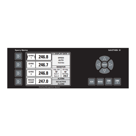
NAVITWIN IV 056344/A Chapter 2: Operation 2.1 Display and Operating Keys Figure 2-1: NAVITWIN IV operating unit DISPLAY DATA GYRO 246.8 SPEED AUTO 12.8 kn GYRO 246.7 MONITOR Hdg. Diff Off Hdg. 10˚ 10˚ GYRO 246.8 Gyro 1 Set Hdg. -
Page 18: External Control Devices
(apply a 180° offset to the heading data) e.g. for operation in double- ended ferries. • The audible alarm at the NAVITWIN IV the may be muted from a remote device, e.g. a central alarm panel. • External pushbuttons may be used to adjust the display brightness. -
Page 19: Selecting The Active Heading Source
WARNING NAVITWIN IV permits to activate a heading source as soon as heading data is received from the respective device. Make sure that a gyrocompass has settled before using its heading as the reference for heading control systems, RADAR, ECDIS, etc. -
Page 20: Selecting Additional Display Data
Gyro 2 ALARM MAGN 247.0 NO ACTIVE COMP ALARM Note The display brightness can only be adjusted in normal operational mode. The brightness setting is not retained between power-ups. NAVITWIN IV always powers up at maximum brightness. Selecting additional display data... -
Page 21: Optional Functions
A remotely muted alarm remains in the pending (unacknowledged) state. The alarm is indicated as pending in the alarm window until the alarm is acknowledged at the NAVITWIN IV or the cause of the alarm is elimi- nated. Resetting/Acknowledging a Central Watch Alarm... -
Page 22: Operating Menu
ALARM Note When the menu mode is active and no key is pressed for more than 30 seconds, the NAVITWIN IV automatically returns to normal operational mode. In the menu mode, the source selector keys are disabled and the bright- ness level cannot be adjusted. -
Page 23: Navigating The Menu
NAVITWIN IV 056344/A Navigating the Menu In the menu mode, the operator may navigate through the menu using the Right, Left, Up and Down arrow keys. The arrow symbol ( ) at the left of XXXXXXXX the window indicates the cursor AAAAAAAA position on the current menu level. -
Page 24: Selecting Parameter Settings
056344/A NAVITWIN IV Selecting Parameter Settings In a number of sub-menus, the operator is expected to select parameter settings from a list of available options. The available options and the current selection are indicated by different symbols: Radio buttons: Allow to select exactly one of the available options. -
Page 25: Off Heading Monitor Settings
NAVITWIN IV 056344/A 2.9 Off Heading Monitor Settings NAVITWIN IV can monitor the difference between the actual heading from the active source and the set heading order in automatic steering modes. The set heading may either be received automatically from a heading or track control system or may be entered manually. -
Page 26: Heading Diff. Monitor Settings
056344/A NAVITWIN IV 2.10 Heading Diff. Monitor Settings NAVITWIN IV can monitor the difference between any two of the availa- ble heading sources. Should this difference exceed the alarm threshold, the “Heading Diff. Alarm” is given. To set the parameters for heading diff. monitoring:... -
Page 27: Manual Settings Menu
Note Some of the manual settings have no direct effect at the NAVITWIN IV but will overwrite the corresponding values at connected gyrocompasses of types NAVIGAT X MK 1, MK 2, or NAVIGAT 2100. - Page 28 056344/A NAVITWIN IV Figure 2-3: contd. from Manual Settings previous page (cont.d) MANUAL SETTINGS NAVIPRINT nav. data printer settings NAVIPRINT RATE OF TURN not implemented in current software release NORTH SP. ERR. C. < BACK < BACK RATE OF TURN...
-
Page 29: Manual Settings - Parameters
NAVITWIN IV 056344/A Manual Settings – Parameters Speed Sets the speed input parameters. This setting is effective for the NAVITWIN IV internally and for all con- nected compasses evaluating the NAVITWIN IV op. data. Mode Selects the speed input mode. Settings:... - Page 30 056344/A NAVITWIN IV Position Sets the position input parameters. This setting is effective for the NAVITWIN IV internally and for all con- nected compasses evaluating the NAVITWIN IV op. data. Mode Selects the position input mode. Settings: AUTO Position data is read automatically from the serial data input...
-
Page 31: Mag Variation
The printer must be set up locally via the manual settings menu at the respective compass(es). The local printer settings will not be overwritten by the NAVITWIN IV, as the printer settings are omitted in the op. data messages sent to the compasses. -
Page 32: Rate Of Turn
Rate of Turn Sets the rate of turn input parameters. This setting is only effective for connected compasses evaluating the NAVITWIN IV op. data. Time Constant Sets the damping time constant for rate of turn data. In NAVIGAT 2100 compasses, the “low” time constant is set. -
Page 33: User Setup
NAVITWIN IV 056344/A 2.12 User Setup The User Setup menu provides access to settings which the operator may need to alter only occasionally. User Setup – Overview Figure 2-4: USER SETUP User Setup DATE & TIME date and time settings DATE &... -
Page 34: User Setup - Parameters
056344/A NAVITWIN IV User Setup – Parameters Date & Time Sets the date and time input parameters. AUTO Selects the date and time input mode. Settings: ON (option checked) Date/time are read automatically from the serial data input OFF (option unchecked) The current date and time are entered manually Man. -
Page 35: Version Info
NAVITWIN IV 056344/A Version Info Displays the system software version info screen. Settings: none The software version sub-menu is read-only. User Setup 2-19... - Page 36 056344/A NAVITWIN IV 2-20 User Setup...
-
Page 37: Chapter 3: Alarm System
GYRO 1 The message background is white. Note Pending alarms from NAVIGAT gyrocompasses (“external alarms”) are indicated and may be acknowledged at the NAVITWIN IV. However, the NAVITWIN IV displays no acknowledged external alarms. Alarm Indication... -
Page 38: Acknowledging Alarms/Muting The Audible Alarm
When the cause of an alarm is eliminated, the alarm is acknowledged automatically and the alarm status is cleared. The NAVITWIN IV does not keep a history of past (inactive) alarms. External Alarm Mute To mute the audible alarm externally (e.g. from a central alarm panel): Actuate the external mute facility. -
Page 39: Viewing The Active Alarms
NAVITWIN IV 056344/A 3.3 Viewing the active alarms If more than one active alarm is present, the total number of alarms and the index number of the currently displayed alarm are shown in the alarm window title bar. To view all active alarms, scroll through the list of alarm messages with... -
Page 40: Alarm Messages
If the system is configured to read back the selection status from the Switch-Over Unit, an alarm is also given when the heading source selec- tion at the NAVITWIN IV differs from the status of the Switch-Over Unit. Table 3-1:... - Page 41 NAVITWIN IV 056344/A message text cause corrective action TIMEOUT No valid data received If source is active, acti- MAGN from magnetic head- vate another source ing source (serial inter- immediately. face) Check function of mag- netic heading source and interface.
-
Page 42: External Alarms (From Navigat Compasses)
External alarms are the alarms transmitted by a NAVIGAT X MK 1, MK 2, or NAVIGAT 2100 gyrocompass. These alarms are displayed and may be acknowledged at the NAVITWIN IV. Once acknowledged, however, external alarms are cleared at the NAVITWIN IV. - Page 43 NAVITWIN IV. MAX ROT EXC. Max. Rate of Turn “Max. ROT Exc. ” alarm alarm threshold reminds the operator exceeded.
- Page 44 NAVIGAT 2100 to normal operation. NTIV COM. FAULT Compass receives no Check the connection valid data from the between NAVITWIN IV NAVITWIN IV. and the gyrocompass. Common parameters in Manual Settings / User Setup menues will not be transmitted to the compass.
-
Page 45: Chapter 4: Scheduled Maintenance
Chapter 4: Scheduled Maintenance 4.1 Maintenance by Shipboard Personnel The NAVITWIN IV is a solid-state electronic device and contains no con- sumable parts. Therefore, no set maintenance schedule is required. The front plate should be kept clean and a regular visual inspection of cables and connectors should be carried out to detect any signs of dam- age or deterioration. - Page 46 056344/A NAVITWIN IV Maintenance by Shipboard Personnel...
-
Page 47: Chapter 5: Installation
Chapter 5: Installation 5.1 Mechanical Installation Console Mounting To mount the NAVITWIN IV directly in a console panel (without console frame) a panel cutout is required as shown in dimensional drawing 4994-0112-02 (see Appendix B). Suitable fasteners for console mounting are provided in the installation kit 22596. -
Page 48: Electrical Installation
If a magnetic heading source is connected to the NAVITWIN IV, the mag- netic compass calibration procedure should be carried out during a sea trial, as described in the following section. -
Page 49: Magnetic Heading Calibration
- the steering magnetic compass is exchanged or newly adjusted, - the magnetic heading sensor is exchanged and, - if a fluxgate sensor is used, when the NAVITWIN IV itself is exchanged. Calibration Procedure The magnetic heading calibration is a two-part procedure. -
Page 50: Determining Magnetic Heading Correction Values
MAGN 000.8 ing magnetic compass with the COMP magnetic heading values shown on the NAVITWIN IV display. At every full 10° of steering magnetic compass heading (0°, 10°, ... , 350°), note the display value. Mag. HDG Mag. -
Page 51: Storing The Magnetic Heading Calibration Table
NAVITWIN IV 056344/A Storing the magnetic heading calibration table 1. Call up the User Setup and go to ’Magn Cal Tab | Enter Values’. MAIN MENU Press ENTER. The calibration table entry screen is USER SETUP shown. MAGN CAL TAB 2. -
Page 52: Deleting Entries From The Magnetic Heading Calibration Table
056344/A NAVITWIN IV Deleting entries from the magnetic heading calibration table When a complete new calibration is carried out, it is recommended to delete old entries from the calibration table first. Also, if the determined correction values are comparatively small, it is generally sufficient to enter only a few values for the headings where the largest deviations occur. -
Page 53: Chapter 6: System Configuration
Chapter 6: System Configuration 6.1 Service Setup Menu The Service Setup menu provides access to the system parameters which configure the NAVITWIN IV according to the requirements of the installation at hand. Setup Access Code To prevent inadvertent or unauthorized changes to the system configu- ration, setup menus which are to be accessed by service personnel only are protected by access codes. -
Page 54: Service-Setup - Overview
056344/A NAVITWIN IV Service-Setup – Overview Figure 6-1: SERVICE SETUP Service Setup GYRO 1 settings for Gyro 1 input GYRO 1 GYRO 2 INTERFACE TYP NMEA-HDT NMEA NAVIGAT PLATH BINARY COMPASS NAME GYRO GYRO 1 GYRO 2 GYRO 3 FOG 1... - Page 55 NAVITWIN IV 056344/A Figure 6-2: contd. from Service Setup previous page (contd.) SERVICE SETUP GYRO 3/MAGN settings for Gyro 3 / Magn. input GYRO 3/MAGN SET HDG./GPS G3 INTERFACE INTERFACE TYP NMEA-HDT NMEA NAVIGAT PLATH BINARY COMPASS NAME GYRO GYRO 1...
- Page 56 056344/A NAVITWIN IV Figure 6-3: contd. from Service Setup previous page (contd.) SERVICE SETUP RS422 OUTP . 1 settings for serial data RS422 OUTP. 2 PORT SETTINGS output 1 INTERNALS MAGN SELECT HCHDG HCHDM HCHDT STATUS SELECT PPLAN PPNSD RS422 OUTP . 2...
- Page 57 NAVITWIN IV 056344/A Figure 6-4: contd. from Service Setup previous page (contd.) SERVICE SETUP INTERNALS system-internal settings INTERNALS < BACK FACTORY SETTINGS reset all setup parameters to factory settings INDIVIDUAL NAME GYRO1 NAME (editable string; 8 chars. max.) GYRO2 NAME (editable string;...
-
Page 58: Service Setup - Parameters
056344/A NAVITWIN IV Service Setup – Parameters Gyro 1 Configures the Gyro 1 input. InterfaceTyp Selects the interface protocol for the Gyro 1 input. Settings: The input is disabled NMEA-HDT The input reads the NMEA $--HDT sentence NMEA NAVIGAT The input reads NMEA data from a Sperry NAVIGAT X MK 1,... -
Page 59: Gyro 2
NAVITWIN IV 056344/A Gyro 2 Configures the Gyro 2 input. InterfaceTyp Selects the interface protocol for the Gyro 2 input. Settings: The input is disabled NMEA-HDT The input reads the NMEA $--HDT sentence NMEA NAVIGAT The input reads NMEA data from a Sperry NAVIGAT X MK 1,... -
Page 60: Gyro 3/Magn
056344/A NAVITWIN IV Gyro 3/Magn. Configures the Gyro 3 and Magnetic Heading inputs. G3 Interface Configures the Gyro 3 input. Interface Typ Selects the interface protocol for the Gyro 3 input. Settings: The input is disabled NMEA-HDT The input reads the NMEA $--HDT sentence... - Page 61 The input reads the NMEA $HCHDM sentence at the G3/MAG interface SIN/COS The input reads analogue voltages from a Sperry Marine fluxgate sensor type 4863 at the analogue fluxgate interface Comp. Name Selects the name for the device at the magnetic heading input.
-
Page 62: Set Hdg./Gps
056344/A NAVITWIN IV Set Hdg./GPS Configures the Set Hdg./GPS input. Protocol Selects the interface protocol for the Set Hdg./GPS input. Settings: The Set Hdg./GPS input is disabled NMEA 4800 The Set Hdg./GPS input reads the NMEA data at 4800 Bd. -
Page 63: Rs422 Outp. 1
NAVITWIN IV 056344/A RS422 Outp. 1 Configures the RS-422 output 1 and the TTL serial data outputs. Magn. Select Selects the output sentence for magnetic heading data. Settings: HCHDG Magnetic heading is sent using the NMEA $--HDG sentence with talker ID “HC”... -
Page 64: Rs422 Outp. 2
056344/A NAVITWIN IV RS422 Outp. 2 Configures the RS-422 serial data output 2. Bd. Rate Selects the transmission baud rate Settings: 4800 Data is transmitted at 4800 Baud (standard according to NMEA / IEC 61162-1) 9600 Data is transmitted at 9600 Baud... - Page 65 NAVITWIN IV 056344/A PPLAA/PPLAB/PPLAD Selects whether the NAVITWIN op. data sentences are transmitted (proprietary sentences $PPLAA, $PPLAB and $PPLAD). Settings: ON (option checked) The NAVITWIN op. data sentences are transmitted OFF (option unchecked) The NAVITWIN op. data sentences are not transmitted XXHDT Selects whether true heading data is transmitted ($--HDT sentence).
-
Page 66: Port Settings
056344/A NAVITWIN IV Port Settings Configures the status input ports. Port 1 Mode Selects the function of status input port 1. Settings: EXT. DIM (+) The port is used for external dimming; brightness is increased one step when input contact is closed... - Page 67 NAVITWIN IV 056344/A 180° Offset Selects the applicable heading sources for the 180° Offset function Settings: GYRO 1 ON (option checked): Gyro 1 heading is reversed when 180° Offset is active. OFF (option unchecked): Gyro 1 heading is not reversed when 180° Offset is active.
-
Page 68: Internals
056344/A NAVITWIN IV Internals Accesses system-internal parameters. Factory Settings Resets all configuration parameters to factory defaults. Settings: none Selecting “Factory Settings” and pressing the “Enter” key resets all configuration parameters to the factory defaults Individual Name Sets the user-editable names for the heading source inputs. -
Page 69: Chapter 7: Troubleshooting
Chapter 7: Troubleshooting 7.1 General Troubleshooting Instructions The NAVITWIN IV is a complex electronic device. In case of malfunction, it would neither be practical nor economical to carry out troubleshooting and servicing in the field down to the level of individual circuit compo- nents. -
Page 70: Location Of Parts On The Navitwin Iv Pcb
NAVITWIN IV 7.2 Location of Parts on the NAVITWIN IV PCB Figure 7-1 below shows the locations of exchangeable components, connectors and diagnostic LED indicators on the NAVITWIN IV PCB. Figure 7-1: location of parts on the NAVITWIN IV PCB... -
Page 71: Exchangeable Components
1 J1 must be placed across pins 1 and 2 (buzzer hi) in normal operation. Placing J1 across pins 2 and 3 (buzzer lo) is permitted only to tempo- rarily silence buzzer during service. Location of Parts on the NAVITWIN IV PCB... -
Page 72: Diagnostic Leds
Diagnostic LEDs As an aid in troubleshooting, a number of diagnostic LED indicators are provided on the NAVITWIN IV PCB. These indicate the presence of sup- ply voltages, activities on the serial data I/O lines and the current states of the status I/O ports. -
Page 73: Chapter 8: Corrective Maintenance
Chapter 8: Corrective Maintenance The NAVITWIN IV is generally not field-serviceable on the component level. Defective devices must be sent back to Sperry Marine for repair. The only corrective maintenance procedures which may be performed by field service personnel are the exchange of the system software and the replacement of the serial RS-422 output driver IC. -
Page 74: Exchanging The Flashboard
8. In case of a console or frame-mounted device, reattach the back cover and mount the NAVITWIN IV in the console. In case of a device in housing with bracket, insert the NAVITWIN IV in the housing and screw on the back cover. -
Page 75: Uploading Software Via The Service Interface
RS-232 service interface on the NAVITWIN IV PCB. At the time of writing of this manual, however, an upload program for field service use is not yet available. Sperry Marine will issue an official Service Bulletin as soon as such a program becomes available. - Page 76 056344/A NAVITWIN IV Replacing the RS-422 Output Driver IC...
-
Page 77: Appendix A: Setup And Configuration Tables
4994-0125-03 Magnetic Compass Calibration Table Note After installation of the NAVITWIN IV, please return a filled-out copy of the Setup Table to Sperry Marine for inclusion in the ship’s file. When permanent changes are made to the system configuration, please... - Page 78 056344/A NAVITWIN IV...
- Page 79 * NAVIPRINT settings not implemented in current software. Printer settings must be entered at the compass(es) directly. User Setup Date/Time Mode AUTO Magn. Cal. Tab. Use Cal. Tab. Northrop Grumman Sperry Marine B.V. (Representative Office) Woltmanstr. 19, D-20097 Hamburg, Germany Tel.: +49-40-299 00-0, Fax: +49-40-299 00-298, E-mail: service.de@sperry.ngc.com...
- Page 81 Service Station / Installer: Date / Signature: Note After installation of the NAVITWIN IV, please return a filled-out copy of the Setup Table to Sperry Marine for inclusion in the ship’s file. When permanent changes are made to the system configuration, please return an updated copy of the Setup Table to Sperry Marine.
- Page 83 MAGN Internals Individ. Name GYRO1 NAME: GYRO2 NAME: GYRO3 NAME: MAGN NAME: LCD Color GRAY STYLE BLUE STYLE BLACK STYLE Northrop Grumman Sperry Marine B.V. (Representative Office) Woltmanstr. 19, D-20097 Hamburg, Germany Tel.: +49-40-299 00-0, Fax: +49-40-299 00-298, E-mail: service.de@sperry.ngc.com...
- Page 85 80.0 260.0 90.0 270.0 100.0 280.0 110.0 290.0 120.0 300.0 130.0 310.0 140.0 320.0 150.0 330.0 160.0 340.0 170.0 350.0 Northrop Grumman Sperry Marine B.V. (Representative Office) Woltmanstr. 19, D-20097 Hamburg, Germany Tel.: +49-40-299 00-0, Fax: +49-40-299 00-298, E-mail: service.de@sperry.ngc.com...
- Page 87 All appended drawings are revision-controlled separately at Sperry Marine. In case of doubt, verify the current revision status of the draw- ings with Sperry Marine. This manual’s revision status does not change when the revision of an appended drawing changes.
- Page 88 056344/A NAVITWIN IV...
Need help?
Do you have a question about the NAVITWIN IV and is the answer not in the manual?
Questions and answers