Table of Contents
Advertisement
Operation, Installation and Service Manual
12
0
Combined Satellite and Electromagnetic Speed Log
Northrop Grumman Sperry Marine B.V. (Representative Office)
Woltmanstr. 19 • D-20097 • Hamburg, Germany
Tel.: +49-40-299 00-0 • Fax: +49-40-299 00-146 • E-mail: service.de@sperry.ngc.com
MASTER
600 SE
GPS QUAL.
GOOD
.
8
0
N.MILES
DAILY
.
1234.56
12
TOTAL
kn
123456.7
NAVIKNOT 600 SE
056349/C, 18 Apr 2008
Advertisement
Table of Contents

Related Manuals for Sperry Marine NAVIKNOT 600 SE


Summary of Contents for Sperry Marine NAVIKNOT 600 SE
- Page 1 1234.56 TOTAL 123456.7 NAVIKNOT 600 SE Combined Satellite and Electromagnetic Speed Log 056349/C, 18 Apr 2008 Northrop Grumman Sperry Marine B.V. (Representative Office) Woltmanstr. 19 • D-20097 • Hamburg, Germany Tel.: +49-40-299 00-0 • Fax: +49-40-299 00-146 • E-mail: service.de@sperry.ngc.com...
- Page 2 © 2008 Northrop Grumman Sperry Marine B.V. This document and the information herein is the intellectual property of Northrop Grumman Sperry Marine B.V. [NGSM BV] and its associate companies and may not be copied or repro- duced without the express permission of NGSM BV.
- Page 3 NAVIKNOT 600 SE 056349/C Safety Instructions Safety Notice Conventions The following safety notice conventions are followed throughout this manual: A Danger notice contains an operating or main- DANGER tenance procedure, practice, condition, state- ment, etc., which, if not strictly observed, will result in injury or death of personnel.
- Page 4 CAUTION The NAVIKNOT 600 SE is type approved as a speed and distance meas- uring equipment only. While the satellite PCB contained in the NAVIKNOT 600 SE electronics unit produces position, heading and rate of turn data, these data are to be regarded internal and may not be used for navigation purposes.
-
Page 5: Table Of Contents
NAVIKNOT 600 SE 056349/C Contents Chapter 1: Introduction Design and Main Features................ 1-1 Data Outputs....................1-2 Operating Principle ................... 1-3 Technical Data.................... 1-4 General....................... 1-4 NAVIKNOT Electronics Unit, Type 5004 ..........1-5 Satellite Antenna Unit................1-8 Preamplifier E, Type 2829 ................. 1-8 EM Log Sensors .................. - Page 6 056349/C NAVIKNOT 600 SE 2.10 User Setup ....................2-13 User Setup – Overview ................2-13 User Setup – Parameters ................ 2-15 Damp. Time Display..............2-15 Damp. Time Output ..............2-15 Damp. Time Docking..............2-15 Reset Daily Miles ................. 2-15 Total Miles Counter ..............2-16 LCD Color..................
- Page 7 NAVIKNOT 600 SE 056349/C Chapter 6: System Configuration Service Setup Menu.................. 6-1 Setup Access Code..................6-1 Service-Setup – Overview ................ 6-2 Service Setup – Parameters ..............6-8 Analog Output ................6-8 Pulse Output ................6-10 RS-422 Output 1–3 ..............6-13 RS422 Output 4–6 ...............
- Page 8 056349/C NAVIKNOT 600 SE Chapter 9: Corrective Maintenance Exchanging the System Software ............9-1 Downloading Software from the Flashboard.......... 9-1 Exchanging the Flashboard............9-2 Uploading Software via the Service Interface......... 9-3 Replacing RS-422 Output Driver ICs ............9-3 Replacing Pulse Output Relays ..............9-3...
-
Page 9: Chapter 1: Introduction
In accordance with the mutual recognition agreement (MRA), USCG approval no. 165.10/EC 0801/4477207has been granted. A basic system consists of the NAVIKNOT 600 SE Electronics Unit, a Control and Display Unit (CDU), a satellite antenna unit and an EM (elec- tromagnetic) speed sensor with the Preamplifier E, type 2863. -
Page 10: Data Outputs
056349/C NAVIKNOT 600 SE Data Outputs Serial speed and distance data is provided in the NMEA 0183 format at six RS-422 outputs. These are divided into two groups of three outputs each, which may be configured independently to suit the receiving equipment. -
Page 11: Operating Principle
NAVIKNOT 600 SE 056349/C 1.2 Operating Principle To determine the longitudinal and transverse ground speeds, the sys- tem makes use of a self-contained satellite sensing system, consisting of the satellite PCB with two GPS receivers inside the electronics unit and the antenna unit connected to it. -
Page 12: Technical Data
056349/C NAVIKNOT 600 SE 1.3 Technical Data General Ground Speed Range, Accuracies and Operating Parameters, Satellite Sensing System measuring range –99 to +99 kn longitudinal –99 to +99 kn transverse accuracy of ground velocity 0.2 kn or 2% of true velocity settling time, heading acquisition 4 min. -
Page 13: Naviknot Electronics Unit, Type 5004
NAVIKNOT 600 SE 056349/C NAVIKNOT Electronics Unit, Type 5004 Environmental Requirements ambient temperature, operation -15°C – +55°C ambient temperature, storage -15°C – +55°C protection grade IP 23 to DIN EN 60529 environmental conditions / EMC in accordance with IEC 60945... - Page 14 056349/C NAVIKNOT 600 SE Data Inputs sensing and status from satellite PCB NMEA 0183 (proprietary sentences) EM sensor speed data NAVIKNOT serial protocol external data (supplementary, not NMEA 0183 / IEC 61162; required for basic system functionality) true heading, rate of turn...
- Page 15 NAVIKNOT 600 SE 056349/C Signal and Status Outputs analogue speed output, voltage max. range -9.999 – 9.999 VDC; speed mapped to output voltage through definition of min. and- max. speed/voltage pairs analogue speed output, current max. range 0 – 20 mA;...
-
Page 16: Satellite Antenna Unit
056349/C NAVIKNOT 600 SE Satellite Antenna Unit Dimensions and Weight width 98 mm height 144 mm depth 776 mm beam supporting the antennas must be aligned parallel or per- pendicular to vessel’s centerline to within ±9° weight 1.9 kg approx. -
Page 17: Em Log Sensors
NAVIKNOT 600 SE 056349/C EM Log Sensors Common Operational Data excitation voltage 24 VAC excitation current 180 μV/kn nominal output voltage Sensor NF, Type 2829 sensor for steel or aluminium ves- sels, single or double bottom installation method from inside vessel, through hull... - Page 18 056349/C NAVIKNOT 600 SE Sensor FNF II, Type 4120 sensor for wooden or glass-fibre vessels installation method from inside vessel, in drydock pressure resistance > 2 bar (2000 hectopascal) cable length 20 m dimensions and weight see drawing 4120-0120-01 weight 15.0 kg...
-
Page 19: Control And Display Unit (Cdu)
NAVIKNOT 600 SE 056349/C Control and Display Unit (CDU) Environmental Requirements ambient temperature, operation -15°C – +55°C ambient temperature, storage -25°C – +70°C protection grade, main CDU and IP 23 to DIN EN 60529 3x1 remote unit protection grade, 2x1 remote unit... - Page 20 056349/C NAVIKNOT 600 SE Dimensions and Weight, Main CDU and 3x1 remote unit PN 73508 (for console mounting) width 192 mm height 96 mm depth 43 mm; approx. 120 mm backward clearance from mounting surface required for connector cable and...
- Page 21 NAVIKNOT 600 SE 056349/C Dimensions and Weight, 2x1 remote unit PN 73506 (for console mounting) width 192 mm height 96 mm depth 44 mm; approx. 100 mm backward clearance from mounting surface required for connector cable and plug weight 2.4 kg...
- Page 22 056349/C NAVIKNOT 600 SE 1-14 Technical Data...
-
Page 23: Chapter 2: Operation
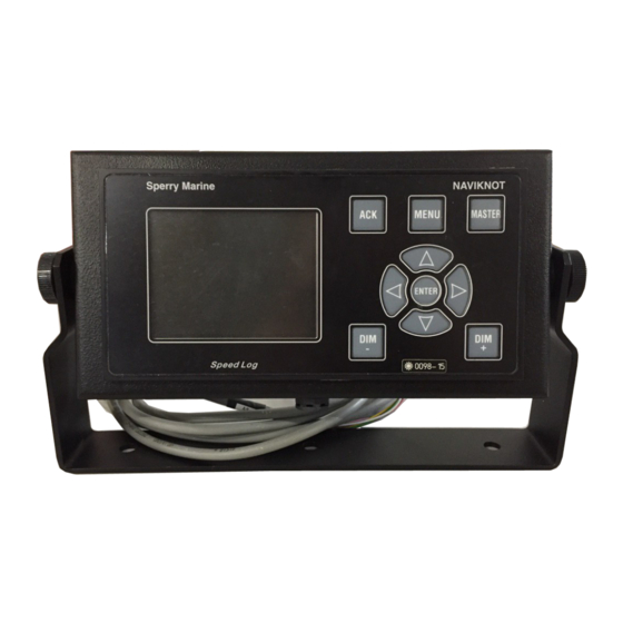
NAVIKNOT 600 SE 056349/C Chapter 2: Operation 2.1 Display and Operating Keys Figure 2-1: NAVIKNOT 600 SE operating unit MASTER 600 SE GPS QUAL. GOOD N.MILES DAILY 1234.56 TOTAL 123456.7 Main Display: shows one of five selectable pages, indicating –... -
Page 24: External Control Devices
Depending on the installation, external devices may be present to remotely control certain functions of the NAVIKNOT 600 SE: • The audible alarm at the NAVIKNOT 600 SE may be muted from a remote device, e.g. a central alarm panel. •... -
Page 25: Display Indications In Normal Operational Mode
056349/C 2.4 Display Indications in Normal Operational Mode Main Display Pages In the normal operational mode, the NAVIKNOT 600 SE CDU perma- nently displays one of the five selectable main display pages. Ground Speed (SOG) The main display shows the actual... - Page 26 056349/C NAVIKNOT 600 SE Docking Display The main display shows a graphical MASTER representation of the vessel, indi- 600 SE cating the actual longitudinal speed GPS QUAL. over ground as well as the trans- GOOD verse ground speeds at the bow 123.45...
-
Page 27: Operating Status Indications
NAVIKNOT 600 SE 056349/C Operating Status Indications Master/Remote status The indication “MASTER” is shown MASTER in the top right corner of the CDU which is currently assigned the REMOTE operating master status. Other CDUs, if present, will show the indi- cation “REMOTE”... -
Page 28: Requesting Master Control
DAILY DAILY 1234.56 TOTAL 123456.7 Note The display brightness can only be adjusted in normal operational mode. The brightness setting is not retained between power-ups. The NAVIKNOT 600 SE always powers up at the second brightest level. Requesting Master Control... -
Page 29: Optional Functions
A remotely muted alarm remains in the pending (unacknowledged) state. The alarm is indicated as pending in the sidebar until the alarm is acknowledged at the NAVIKNOT 600 SE or the cause of the alarm is elim- inated. Resetting/Acknowledging a Central Watch Alarm... -
Page 30: Operating Menu
056349/C NAVIKNOT 600 SE 2.8 Operating Menu The manual settings, user and service setup sub-menus are accessed through a multilevel operating menu. Entering and Quitting the Menu Mode From the normal operational MASTER mode, press MENU to enter 600 SE GPS QUAL. -
Page 31: Navigating The Menu
NAVIKNOT 600 SE 056349/C Navigating the Menu In the menu mode, the operator may navigate through the menu using the Right, Left, Up and Down arrow keys. Arrow symbols (>) to the MAIN MENU MAIN MENU right of the window indicate... -
Page 32: Selecting Parameter Settings
056349/C NAVIKNOT 600 SE Selecting Parameter Settings In a number of sub-menus, the operator is expected to select parameter settings from a list of available options. The available options and the current selection are indicated by different symbols: Radio buttons: Allow to select exactly one of the available options. -
Page 33: Manual Settings Menu
NAVIKNOT 600 SE 056349/C 2.9 Manual Settings Menu The Manual Settings menu provides access to settings which the opera- tor may need to alter more or less frequently during normal operation. Manual Settings – Overview Figure 2-2: MAIN MENU Manual Settings MANUAL SETTINGS >... -
Page 34: Manual Settings - Parameters
056349/C NAVIKNOT 600 SE Manual Settings – Parameters Speed Mode STW Selects the input mode for water speed data. Settings: The actual speed value is entered manually. This setting may be activated only temporarily, to generate water speed output data in case of failure of the EM log sen- sor or for testing. -
Page 35: User Setup
NAVIKNOT 600 SE 056349/C 2.10 User Setup The User Setup menu provides access to settings which the operator may need to alter only occasionally. User Setup – Overview Figure 2-3: MAIN MENU User Setup USER SETUP > > DAMP. TIME DISPLAY >... - Page 36 056349/C NAVIKNOT 600 SE Figure 2-4: contd. from previous page User Setup (cont.d) SCALE > > SCALE speed display units SPEED SCALE FT/S DOCKING SPEED SCALE FT/S SOFTWARE VERSION NN.NN > > SOFTWARE VERSION NAVIKNOT El. Unit software version version ID (read-only)
-
Page 37: User Setup - Parameters
NAVIKNOT 600 SE 056349/C User Setup – Parameters Damp. Time Display Sets the damping time constant for the ground and water speed display. The higher the time constant, the stronger sudden peaks of the actual speed will be damped in the ground and water speed display pages. -
Page 38: Total Miles Counter
056349/C NAVIKNOT 600 SE Total Miles Counter Sets the total miles counters to desired start values. Values: Water start value 0.0 – 999999.9 NM Ground start value 0.0 – 999999.9 NM Note The total miles counters may be set to any desired start value. -
Page 39: Software Version
NAVIKNOT 600 SE 056349/C Docking Speed Scale Unit of measure for the docking display page Settings: Speed is displayed in knots. Speed is displayed in metres per second. FT/S Speed is displayed in feet per second. Software Version Displays the software version of the NAVIKNOT Electronics Unit. - Page 40 056349/C NAVIKNOT 600 SE 2-18 User Setup...
-
Page 41: Chapter 3: Alarm System
NAVIKNOT 600 SE 056349/C Chapter 3: Alarm System 3.1 Alarm Indication Audible Alarm Indication Single Beep: Invalid Action A single short beep indicates that the operator attempted to carry out an invalid action. This is the case e.g. if the operator attempts to enter the menu mode from a remote unit. -
Page 42: Acknowledging Alarms/Muting The Audible Alarm
When the cause of an alarm is eliminated, the alarm is acknowledged automatically and the alarm status is cleared. The NAVIKNOT 600 SE does not keep a history of past (inactive) alarms. External Alarm Mute To mute the audible alarm externally (e.g. from a central alarm panel): Actuate the external mute facility. -
Page 43: Viewing The Active Alarms
NAVIKNOT 600 SE 056349/C 3.3 Viewing the active alarms In all main display pages except the alarm page, the total number of active alarms and the error code of the newest alarm are shown in the sidebar. If more than one alarm is active, the Left or Right arrow keys will scroll through the respective error codes. -
Page 44: Error Codes And Messages
056349/C NAVIKNOT 600 SE 3.4 Error Codes and Messages Table 3-1: code message text cause corrective action error messages none WAITING FOR Communcation Check operation of MAIN UNIT between electron- the electronics unit; (shown on startup ics unit and CDU(s) - Page 45 NAVIKNOT 600 SE 056349/C code message text cause corrective action EXT DIM TIMEOUT No valid com- Check connection mands received at between dimming serial dim input. device and elec- tronics unit. EU TIMEOUT Communication Check basic opera- lost between elec-...
- Page 46 056349/C NAVIKNOT 600 SE Error Codes and Messages...
-
Page 47: Chapter 4: Scheduled Maintenance
Chapter 4: Scheduled Maintenance 4.1 Maintenance by Shipboard Personnel Electronics Unit, CDU and Antenna Unit The electronic components of the NAVIKNOT 600 SE system are solid- state devices and contain no consumable parts. Therefore, no set main- tenance schedule is required. - Page 48 056349/C NAVIKNOT 600 SE Maintenance by Shipboard Personnel...
-
Page 49: Chapter 5: Installation
NAVIKNOT 600 SE 056349/C Chapter 5: Installation 5.1 Mechanical Installation Antenna Unit The antenna unit consists of a bow and stern GPS antenna mounted on a beam-shaped support. The arrow on the support must point either ahead or to the port side. The chosen orientation must be entered in the GPS setup menu during system configuration. -
Page 50: Em-Log Sensor And Preamplifier
The installation kit contains connectors intended for use of the satellite PCB in the NAVISTAR satellite compass system. These are not required in the NAVIKNOT 600 SE system, at the electronics unit is delivered prewired with all internal connections between the satellite and process- ing PCBs being installed at the factory. -
Page 51: Control And Display Units
NAVIKNOT 600 SE 056349/C Control and Display Units Console Mounting 3x1 CDU (main or remote) To mount a NAVIKNOT 3x1 CDU directly in a console panel (without con- sole frame), a panel cutout is required as shown in drawing 5002-0112- 02 (see Appendix). -
Page 52: Electrical Installation
056349/C NAVIKNOT 600 SE 5.2 Electrical Installation Preamplifier E, Type 2863, AC Power Configuration The preamplifier is delivered prewired for connection to 230VAC. If the amplifier is required to operate on 115 VAC, it must be reconfigured accordingly. Details of the AC power configuration are described in the applicable installation, maintenance and service instructions for the sensor. -
Page 53: Configuring The Cdu(S)
NAVIKNOT 600 SE 056349/C Configuring the CDU(s) If one CDU is installed only, the unit requires no further configuration. In case more than one CDU is installed, each CDU must be assigned a unique ID through its local Service Setup menu. -
Page 54: Cdu Service Setup - Overview
056349/C NAVIKNOT 600 SE CDU Service Setup – Overview Figure 5-4: SERVICE SETUP CDU Service Setup > > CDU ID > > CDU ID this CDU's local ID ID: 0 – 9 > > DIMMING > > DIMMING settings for... -
Page 55: Cdu Service Setup - Parameters
The factory default for the offset is 0. Dim Values (min. through max.) Maps the ordered brightness setting as read from the serial dim com- mand to the NAVIKNOT 600 SE’s nine discrete brightness levels. Settings: 00 – 99 For each brightness level, set the smallest intensity order at which the level should be active. -
Page 56: Configuring System Parameters
NAVIKNOT 600 SE system are available through the Service Setup. After the initial system configuration, note all settings in the NAVIKNOT 600 SE system setup table (see Appendix). Send one copy of the filled-out table to Sperry Marine for inclusion in the ship’s file. -
Page 57: Chapter 6: System Configuration
Chapter 6: System Configuration 6.1 Service Setup Menu The Service Setup menu provides access to the system parameters which configure the NAVIKNOT 600 SE according to the requirements of the installation at hand. Setup Access Code To prevent inadvertent or unauthorized changes to the system configu- ration, setup menus which are to be accessed by service personnel only are protected by access codes. -
Page 58: Service-Setup - Overview
056349/C NAVIKNOT 600 SE Service-Setup – Overview Figure 6-1: SERVICE SETUP Page 1 Service Setup, page 1 > > NEXT PAGE (2) > > skip to page 2 > > ANALOG OUTPUT > > ANALOG OUTPUT settings for analogue speed outputs... - Page 59 NAVIKNOT 600 SE 056349/C Figure 6-2: contd. from previous page Service Setup, page 1 (contd.) > > PULSE OUTPUT > > PULSE OUTPUT settings for pulse outputs PULSE OUTPUT 1–3 PULSE/NM 10 PULSE/NM 100 PULSE/NM 200 PULSE/NM 400 PULSE/NM 20000 PULSE/NM SOURCE PULSE OUTPUT 4–5...
- Page 60 BAUDRATE 4800 BAUD 9600 BAUD 38400 BAUD DATA LOGGER data logging function for factory use only; do not alter settings or access menu unless instructed by Sperry Marine. > > RS422 OUTPUT 4-6 > > RS422 OUTPUT 4–6 settings for RS-422 outputs group 2 (outp.4-6)
- Page 61 NAVIKNOT 600 SE 056349/C Figure 6-4: contd. from previous page Service Setup, page 1 (contd.) > > NMEA INPUT 1 > > NMEA INPUT 1 settings for NMEA input 1 MESSAGES PPLAI BAUDRATE 4800 BAUD 9600 BAUD 38400 BAUD >...
- Page 62 056349/C NAVIKNOT 600 SE Figure 6-5: SERVICE SETUP Page 2 Service Setup, page 2 > > NEXT PAGE (1) > > skip to page 1 > > SYSTEM TYPE > > SYSTEM TYPE system type configuration NAVIKNOT 600SE type must be set to 600SE >...
- Page 63 NAVIKNOT 600 SE 056349/C Figure 6-6: contd. from previous page Service Setup, page 2 (contd.) > > GPS SETUP > > GPS SETUP access satellite PCB setup access setup menu of the satellite PCB (sub-menu pages served from satellite PCB) >...
-
Page 64: Service Setup - Parameters
056349/C NAVIKNOT 600 SE Service Setup – Parameters Analog Output Configures the analogue speed outputs (voltage and current output). Source Selects the data source for the analogue outputs. Setting: The outputs provide the actual speed over ground The outputs provide the actual speed through the water Voltage Configures the analogue output voltage range. - Page 65 NAVIKNOT 600 SE 056349/C Current Configures the analogue output current range. The output current range is defined by two pairs of values: The minimum speed and associated minimum current determine the lower limit of the output range, while the maximum speed and associ- ated maximum current define its upper limit.
-
Page 66: Pulse Output
This signal, a 100 ms pulse, is used to mute the audible alarm indication at a central alarm facility when the respective alarm is acknowledged locally at the NAVIKNOT 600 SE CDU. Pulse Output 1–3 Configures group 1 of the pulse outputs (outputs 1 – 3). - Page 67 NAVIKNOT 600 SE 056349/C Pulse Output 4–5 Configures group 2 of the pulse outputs (outputs 4– 5). Pulse/NM Selects the output pulse frequency. Setting: 10 Pulse/NM The output delivers 10 pulses per nautical mile. 100 Pulse/NM The output delivers 100 pulses per nautical mile.
- Page 68 20000 Pulse/NM The output delivers 20000 pulses per nautical mile. MUTE RELAY When an alarm is acknowledged locally at the NAVIKNOT 600 SE CDU, the output delivers a pulse to mute the audible alarm indication at a central alarm facility. Source Selects the data source for pulse output 6.
-
Page 69: Output 1-3
Messages Selects the NMEA sentences to transmit. If the NAVIKNOT 600 SE cannot provide valid data for an NMEA sen- tence field, a null field (empty field) is sent. Status fields for invalid or unknown data are marked invalid (“V“). Other sentences than those described below must not be activated for the NAVIKNOT 600 SE. - Page 70 056349/C NAVIKNOT 600 SE Data Logger Puts the output into a special data logging mode. This option is intended for test purposes only and must never be acti- vated during normal operation. If the logging mode is made active, the serial data outputs 1–3 do no longer provide regular NMEA data.
-
Page 71: Rs422 Output 4-6
Messages Selects the NMEA sentences to transmit. If the NAVIKNOT 600 SE cannot provide valid data for an NMEA sen- tence field, a null field (empty field) is sent. Status fields for invalid or unknown data are marked invalid (“V“). Other sentences than those described below must not be activated for the NAVIKNOT 600 SE. -
Page 72: Nmea Input 1
056349/C NAVIKNOT 600 SE NMEA Input 1 Configures the NMEA input 1. Messages Selects the NMEA sentences to receive. Settings: Enables the input to receive true heading data from the $--HDT sentence. Selecting this option lets the system ignore heading data from the satellite PCB in favour of the external data. -
Page 73: Nmea Input 2
NAVIKNOT 600 SE 056349/C NMEA Input 2 Configures the NMEA input 2. Messages Selects the NMEA sentences to receive. Settings: Enables the input to receive true heading data from the $--HDT sentence. Selecting this option lets the system ignore heading data from the satellite PCB in favour of the external data. -
Page 74: System Type
056349/C NAVIKNOT 600 SE System Type Configures the NAVIKNOT system type. For the NAVIKNOT 600 SE, the type must be set to 600SE; all other options are to be ignored. Settings: NAVIKNOT 600 SE Sensor Sensitivity Sets the sensitivity value for the EM-Log sensor. -
Page 75: Relay Speed Limit
NAVIKNOT 600 SE 056349/C Relay Speed Limit Sets the lower and/or upper switching thresholds for the speed limit relay output. The speed limit relay output provides a status signal to external equip- ment, to indicate that the actual speed has exceeded or fallen below a set threshold. - Page 76 056349/C NAVIKNOT 600 SE Minimum Value Sets the lower switching threshold for the limit relay. Value: -99.9 – +99.9 kn Minimum Value ON Activates or de-activates switching at the lower threshold Settings: ON (option checked) Switching is active at the lower threshold...
-
Page 77: Calibration
Activates or de-activates the calibration table. Settings: ON (option checked) Calibration is active. The NAVIKNOT 600 SE corrects the data received from the preamplifier according to the calibra- tion table. The resulting calibrated speed is displayed and transmitted at the data outputs. -
Page 78: Gsp Setup
056349/C NAVIKNOT 600 SE GSP Setup Accesses the satellite PCB configuration menu Settings: the GPS setup menu pages are directly served by the satel- lite PCB; refer to section 6.2, “GPS Setup”, for a detailed description of the GPS setup menu. -
Page 79: Gps Setup
NAVIKNOT 600 SE setup. Note Some of the available GPS configuration options do not apply to the NAVIKNOT 600 SE system. These must be left at the factory default set- tings as noted in the GPS setup descriptions below. GPS Setup Operation (solid arrow): Indicates the current cursor position on the screen (equivalent to angle bracket symbol in the NAVIKNOT 600 SE setup). -
Page 80: Gps Setup - Overview
056349/C NAVIKNOT 600 SE GPS Setup – Overview Figure 6-7: GPS SETUP (EXTERNAL) GPS Setup pages TOP MENU Heading Selection Heading Selection Align and Calibrate Heading Selection GPS must be ON and active 123.4° MAG must be OFF ---.-° ---.-°... -
Page 81: Gps Setup - Parameters
Configures the heading sources available to the satellite PCB. The currently active source provides the heading sent from the satellite PCB to the NAVIKNOT 600 SE electronics unit. Only the GPS source may be made active, i.e. the satellite PCB must always determine the vessel’s heading internally from the two GPS... - Page 82 Sets the correction values (“deltas”) to compensate for existing offsets of the heading sources relative to the vessel’s fore-and-aft line. As only the GPS source is used within the NAVIKNOT 600 SE system, a delta value must be entered for the GPS source only. This compensates for misalignment of the GPS antenna support with the vessel’s fore-and-...
- Page 83 Calibrates the magnetic heading sensor on the satellite PCB. The magnetic heading sensor contained on the satellite PCB is not suita- ble for use within the NAVIKNOT 600 SE system. Therefore it must not be calibrated. Do not carry out the Mag. at Sea Cal. procedure. Leaving the sensor in the uncalibrated state will prevent it from being activated by accident.
- Page 84 056349/C NAVIKNOT 600 SE 6-28 GPS Setup...
-
Page 85: Chapter 7: Em Sensor Calibration
056349/C Chapter 7: EM Sensor Calibration Once the NAVIKNOT 600 SE system has been installed and the basic configuration carried out, the EM sensor must be calibrated to make sure that the system’s water speed and distance outputs meet the speci- fied accuracy. -
Page 86: Sensor Calibration
7.2 Sensor Calibration To minimize the deviation between the vessel’s actual water speed and the speed displayed and transmitted, the NAVIKNOT 600 SE stores sen- sor-specific calibration data in a so-called calibration table. The calibration table holds up to 21 entries, so-called calibration points, each of which consist of an uncalibrated and a corresponding true water speed value. -
Page 87: Editing The Calibration Table Directly
NAVIKNOT 600 SE 056349/C Editing the Calibration Table Directly To add, edit or delete calibration points directly, go to page 2 of the Service Setup and select the Calibration | Cal.Table sub-menu. The data stored at calibration point no. 00 is shown (dashes will appear if the table is empty). -
Page 88: Zero Point Calibration
056349/C NAVIKNOT 600 SE Zero Point Calibration Before any entries for non-zero speeds are stored in the calibration table or calibration trial runs are conducted, the zero point calibration should be carried out. The “zero point” refers to the calibration table entry which holds the uncalibrated (“raw“) speed value corresponding to a true water speed of... -
Page 89: Automatic Entry
NAVIKNOT 600 SE 056349/C Automatic Entry With the automatic entry method, the required zero point setting is determined automatically. Automatic entry may only be used when the vessel is stationary in waters free of current, i.e., if the actual water speed is known to be zero. -
Page 90: Calibration By Trial Runs
However, as the NAVIKNOT 600 SE obtains the vessel’s current position from the sattelite PCB, it is equally acceptable to start the run clock at a given point in time and to stop it as soon as a distance of at least one mile has been traversed. -
Page 91: Two Way Trial Run
NAVIKNOT 600 SE 056349/C Two Way Trial Run Note During a two way trial run, the vessel’s heading during runs A and B should ideally be parallel to the direction of the effective drift, as the drift component perpendicular to the heading cannot be compensated for. - Page 92 056349/C NAVIKNOT 600 SE The display again indicates the run distance, the average uncali- brated speed, the true speed over ground and the calculated calibra- tion value. 10. Press ENTER to store the run parameters. The Two Way Trial Run sub-menu is quit automatically.
-
Page 93: One Way Trial Run
NAVIKNOT 600 SE 056349/C One Way Trial Run Note In a one way trial run, any drift due to wind and/or current will adversely affect the calibration. Conducting a one way trial run in the presence of drift, may degrade instead of improve the speed accuracy. - Page 94 056349/C NAVIKNOT 600 SE 7-10 Sensor Calibration...
-
Page 95: Chapter 8: Troubleshooting
Chapter 8: Troubleshooting 8.1 Electronics Unit and CDU(s) The NAVIKNOT 600 SE electronics unit and the CDU are complex elec- tronic devices. In case of malfunction, it would neither be practical nor economical to carry out troubleshooting and servicing in the field down to the level of individual circuit components. -
Page 96: Location Of Parts On The Processor Pcb
Location of Parts on the Processor PCB Figure 8-1 below shows the locations of exchangeable components, connectors and diagnostic LED indicators of the processor PCB in the NAVIKNOT 600 SE electronics unit. Figure 8-1: location of parts on the processor PCB... -
Page 97: Exchangeable Components, Processor Pcb
NAVIKNOT 600 SE 056349/C Exchangeable Components, Processor PCB Table 8-1: Part Function Stock No. Exchangeable Flash- Flahsboard (flash-memory card), 020705-0000-000 components on the board pre-programmed with system software processor PCB IC 2 quad RS-422 output driver IC; 046485-0000-000 drives serial data RS-422 outputs 1 to 3 IC 14 photocoupler/photo relay;... -
Page 98: Diagnostic Leds, Processor Pcb
056349/C NAVIKNOT 600 SE Diagnostic LEDs, Processor PCB As an aid in troubleshooting, a number of diagnostic LED indicators are provided on the processor PCB. These indicate the presence of supply voltages, activities on the serial data I/O lines and the current states of the status I/O ports. -
Page 99: Location Of Parts On The Satellite Pcb
Location of Parts on the Satellite PCB Figure 8-2 below shows the locations of relevant connectors, diagnostic LED indicators and the power switch of the satellite PCB inside the NAVIKNOT 600 SE electronics unit. Figure 8-2: location of parts on the... -
Page 100: Connectors And Power Switch, Satellite Pcb
056349/C NAVIKNOT 600 SE Connectors and Power Switch, Satellite PCB Table 8-4: Function Connnectors and 24 VDC supply power in from processor PCB; power switch on the factory prewired: satellite PCB satellite PCB processor PCB J 1.1 – TB 1.3 J 1.2... -
Page 101: Em Sensor And Preamplifier
NAVIKNOT 600 SE 056349/C 8.2 EM Sensor and Preamplifier Malfunction of the EM sensor, resulting in a “Sensor1 Failure” alarm being given, may be caused by a mechanical or electrical defect in the sensor or by a defective preamplifier. As the preamplifier contains no built-in test circuitry, only a basic electrical check is possible in the field. - Page 102 056349/C NAVIKNOT 600 SE EM Sensor and Preamplifier...
-
Page 103: Chapter 9: Corrective Maintenance
NAVIKNOT 600 SE 056349/C Chapter 9: Corrective Maintenance The NAVIKNOT 600 SE CDU, the PCBs inside the electronics unit and the EM-Log preamplifier are generally not field-serviceable on the compo- nent level. Defective devices must be sent back to Sperry Marine for repair. -
Page 104: Exchanging The Flashboard
056349/C NAVIKNOT 600 SE Exchanging the Flashboard 1. Power down the NAVIKNOT 600 SE system. 2. Open the electronics unit and locate the old flashboard in its socket (J7) on the PCB. 3. Carefully remove the plastic pin which secures the flashboard to the PCB. -
Page 105: Uploading Software Via The Service Interface
RS-232 service interface on the electronics unit PCB. At the time of writing of this manual, however, an upload program for field service use is not yet available. Sperry Marine will issue an official Service Bulletin as soon as such a program becomes available. - Page 106 056349/C NAVIKNOT 600 SE Replacing Pulse Output Relays...
-
Page 107: Appendix
NAVIKNOT 600 SE Record of Calibration Trial Runs 5004-0125-04 Note After installation of the NAVIKNOT 600 SE, please return a filled-out copy of the Setup Table to Sperry Marine for inclusion in the ship’s file. When permanent changes are made to the system configuration, please return an updated copy of the Setup Table to Sperry Marine. - Page 108 056349/C NAVIKNOT 600 SE...
- Page 109 Messages Baudrate 4800 Baud 4800 Baud 9600 Baud 9600 Baud 38400 Baud 38400 Baud VLW extended VLW extended PPLAK PPLAK PEDIB PEDIB Northrop Grumman Sperry Marine B.V. (Representative Office) Woltmanstr. 19, 20097 Hamburg, Germany Tel.: +49-40-29900-0, Fax: +49-40-29900-298, E-mail: service.de@sperry.ngc.com...
- Page 111 Port D Output Sel. not applicable in NAVIKNOT systems To Stern (m): To Centerline (m): Antenna Distances To Bow (m): Northrop Grumman Sperry Marine B.V. (Representative Office) Woltmanstr. 19, 20097 Hamburg, Germany Tel.: +49-40-299 00-0, Fax: +49-40-299 00-298, E-mail: service.de@sperry.ngc.com...
- Page 113 (°) avg. uncal. spd. true water speed Run A (or single run) Run B (return run) averaged values (cal. table entry) Northrop Grumman Sperry Marine B.V. (Representative Office) Woltmanstr. 19, 20097 Hamburg, Germany Tel.: +49-40-29900-0, Fax: +49-40-29900-298, E-mail: service.de@sperry.ngc.com...
Need help?
Do you have a question about the NAVIKNOT 600 SE and is the answer not in the manual?
Questions and answers