
Related Manuals for Ethernet Direct Husky HMG-838PT

Summary of Contents for Ethernet Direct Husky HMG-838PT
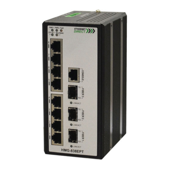
- Page 1 HMG-838PT HMG-838EPT Industrial 8 x 10/100Base-T(X) + 3 x 100/1000Base SFP Gigabit Managed Ethernet Switch User’s Manual (Web Configuration) V1.3 11-06-2017...
- Page 2 Husky Series Industrial Ethernet Switch Solutions HMG-838PT & HMG-838EPT Industrial Gigabit Managed Ethernet Switch User’s Manual (Web Configuration) Copyright Notice Copyright © 2017 Ethernet Direct Corp. All rights reserved. Reproduction in any form or by any means without Ethernet Direct prior written permission is prohibited.
-
Page 3: Table Of Contents
Table of Contents Chapter 1 Web Configuration Home ..............................1 Entering Web Configuration..............................1 Port State ..................................1 Refresh .....................................2 Save ....................................2 Help ....................................2 Logout....................................2 Chapter 2 System ....................................1 System Information Configuration.............................1 System Information................................1 System IP ..................................2 System IP Status ................................3 System NTP..................................4 System Time ..................................5 System Log..................................5 Detailed Log..................................6... - Page 4 5-1.7.6 SNMPv3 View Configuration ..........................11 5-1.7.7 SNMPv3 Access Configuration.........................12 5-1.8 RMON ................................13 5-1.8.1 RMON Statistics Configuration .........................13 5-1.8.2 RMON History Configuration ..........................13 5-1.8.3 RMON Alarm Configuration ..........................13 5-1.8.4 RMON Event Configuration ..........................14 5-1.8.5 RMON Statistics Overview ..........................15 5-1.8.6 RMON History Overview ..........................16 5-1.8.7 RMON Alarm Overview ............................16 5-1.8.8 RMON Event Overview ............................17 Network ..................................17...
- Page 5 5-3.2 RADIUS Overview ............................46 5-3.3 RADIUS Details ..............................46 TACACS+ ..................................49 Chapter 6 Aggregation ..................................1 Static ....................................1 LACP ....................................2 6-2.1 Port Configuration...............................2 6-2.2 System Status ..............................3 6-2.3 Port Status................................3 6-2.4 Port Statistics..............................4 Chapter 7 Redundancy..................................1 Direct-Ring..................................1 7-1.1 Configuration ..............................1 7-1.2 Status .................................5 Loop Protection.................................5 7-2.1 Configuration ..............................6...
- Page 6 10-2.5 Groups Information.............................9 10-2.6 IPv6 SFM Information............................10 Chapter 11 LLDP ....................................1 11-1 Configuration ..................................1 11-2 LLDP-MED..................................3 11-3 Neighbors ..................................5 11-4 LLDP-MED Neighbors ..............................5 11-5 LLDP EEE..................................5 11-6 LLDP Global Counters ..............................6 Chapter 12 MAC Table ..................................1 12-1 Configuration ..................................1 12-2 MAC Address Table ................................2 Chapter 13 VLAN Translation ................................1 13-1 Port to Group Mapping ..............................1 13-2 VID Translation Mapping ..............................1...
- Page 7 21-2 Status....................................4 Chapter 22 L2CP ....................................1 Chapter 23 Diagnostics ..................................1 23-1 Ping ....................................1 23-2 Ping6 ....................................1 23-3 Traceroute ..................................2 Chapter 24 Maintenance..................................1 24-1 Reboot ....................................1 24-2 Factory Defaults................................1 24-3 Software....................................1 24-3.1 Upload ................................1 24-3.2 Image Select ..............................2 24-4 Configuration ..................................2 24-4.1 Save startup-config.............................2 24-4.2...
-
Page 8: Chapter 1 Web Configuration Home
IP address “192.168.16.1” in your web browser. Then, a standard login prompt will appear depending on the type of browser used. The example below is with Chrome browser. Enter the Ethernet Direct factory default username “admin” with “no password”. After successfully entering the web based management, the Port State page will appear. -
Page 9: Refresh
Web Configuration Home "Green" port indicates a LAN connection with a speed of 100M. The "Amber" colored port indicates a LAN connection speed of 1000M. The status display can be reached by using the left side menu, and return to Ports > State. 1-3 Refresh To update the screen, click the "Refresh"... - Page 10 Web Configuration Home After clicking the logout icon, a confirmation screen will be displayed. Click "OK" to finish logging out or click "Cancel" to return to the web configuration GUI. For the remainder of this section, each menu item will be explained one by one, in order as they descend down the menu screen, starting with the "System"...
-
Page 11: Chapter 2 System
Chapter 2 System The configuration under the "System" menu includes device settings such as IP address, time server, etc. System Information Configuration The configuration information entered here will be reported in the standard SNMP MIB2 for 'sysContact' (OID 1.3.6.1.2.1.1.4), 'sysName' (OID 1.3.6.1.2.1.1.5) and 'sysLocation' (OID 1.3.6.1.2.1.1.6). Remember to click the “Save” button after entering the configuration information. -
Page 12: System Ip
System System IP The section allows you to setup the switch’s IP configuration, interface and routes. IP Configuration: Mode: The pull-down configures whether the IP stack should act as a Host or a Router. Host: IP traffic between interfaces will not be routed. Router: Traffic is routed between all interfaces. -
Page 13: System Ip Status
System IP Interface: Click "Add Interface" to add a new IP interface. A maximum of 8 interfaces is supported. VLAN: This is the VLAN associated with the IP interface. Only ports in this VLAN will be able to access the IP interface. -
Page 14: System Ntp
System Please refer to “System IP” for the configuration of the interfaces and routes. This page is informational only. System NTP Display the status of IP interfaces and routes. NTP Configuration: Mode: Configure the NTP mode operation. Possible modes are: Enabled: Enable NTP client mode operation. -
Page 15: System Time
System System Time Setup the switch’s time from which time zone and daylight saving time mode. The setting example above is for Eastern Standard Time in the United States. Daylight savings time starts on the second Sunday in March at 2:00AM. Daylight savings ends on the first Sunday in November at 2:00AM. The daylight savings time offset is 60 minutes (1 hour). -
Page 16: Detailed Log
System Setup a single or the multiple Remote System Log Servers on this page. The max. remote system log server can setup to 3 servers. System Log Configuration: Server Mode: This sets the server mode operation. When the mode of operation is enabled, the syslog message will send out to syslog server (at the server address). -
Page 17: System Smtp
System The load is measured as averaged over the last 100ms, 1sec and 10 seconds intervals. The last 120 samples are graphed, and the last numbers are displayed as text as well. In order to display the SVG graph, your browser must support the SVG format. - Page 18 System SMTP Port: Set the SMTP port number. The default SMTP port is 25. Server requires authentication: Check this box if your server requires authentication. In most cases, this is required and the following must be entered. Username: Enter the valid authentication username for SMTP server Password: Enter the authentication password for username of SMTP server Recipient mail address: Up to four recipient's E-mail addresses may be entered to be sent alert emails.
-
Page 19: Chapter 3 Green Ethernet
Chapter 3 Green Ethernet The configuration under the "Green Ethernet" menu includes a number of power saving techniques. Green Ethernet LED Configure the LED light intensity to reduce power consumption. LED Power Reduction Configuration: The LED light intensity may be adjusted in a percentage of intensity during programmable time periods. In the above setting example, the LED intensity has been adjusted to 50% during daylight hours and reduced to only 10% intensity during night hours. - Page 20 Green Ethernet Port Power Savings Configuration: Optimize EEE for: Enables/disables the EEE function for this switch. The two options are: Power: The EEE function is enabled. This is the default setting. Legacy: EEE is not enabled. Port Configuration: ActiPHY™: ActiPHY™ works by lowering the power for a port when there is no link. The port is power up for short moment in order to determine if an Ethernet cable is inserted.
-
Page 21: Green Ethernet Status
Green Ethernet transmission until a burst of frames can be transmitted. Green Ethernet Status Display the energy saving status for all ports. Port Power Savings Status: In the above we can see that port 8 is saving power through PerfectReach™ as the Ethernet cable is short. Our port 6 is connected to an EEE compliant device but with short cable, so we have savings both by EEE and PerfectReach™. -
Page 22: Chapter 4 Ports
Chapter 4 Ports Configurations related to the fiber and electrical ports are performed under the Ports menu. Ports Configuration This page displays current port configurations and allows some configuration here. Port Configuration: Port: This device is an industrial switch with 8 electrical LAN ports numbered 1~8 and 3 fiber optical ports (for SFP modules) numbered 9~11. -
Page 23: Ports State
Ports Possible copper port settings are: Disabled: Disables the switch port operation. Auto: Port auto negotiating speed with the link partner, selecting the highest speed that is compatible with the link partner and negotiating the duplex mode. 10Mbps HDX: Forces the port to 10Mbps half duplex mode. 10Mbps FDX: Forces the port to 10Mbps full duplex mode. -
Page 24: Ports Traffic Overview
Ports indicate a 100M linked state, while "Amber" colored ports indicate a 1G linked state. "Dark Grey" ports have no link. The link status display can be updated by clicking the "Refresh" button. When "Auto-refresh" is checked, the display will be updated every seconds. -
Page 25: Ports Qcl Status
Ports Rx/Tx: The number of received and transmitted packets per queue. Ports QCL Status This page shows the QCL status by different QCL users. QoS Control List Status: Each row describes the QCE that is defined. It is a conflict if a specific QCE is not applied to the hardware due to hardware limitations. - Page 26 Ports Detailed Port Statistics (Port 1: Port number selectable): Receive Total and Transmit Total: Rx and Tx Packets: The number of received and transmitted (good and bad) packets. Rx and Tx Octets: The number of received and transmitted (good and bad) bytes. Includes FCS, but excludes framing bits.
-
Page 27: Utp Cable Diagnostics
Ports Rx Jabber: The number of long frames received with invalid CRC. Rx Filtered: The number of received frames filtered by the forwarding process. Short frames are frames that are smaller than 64 bytes. Long frames are frames that are longer than the configured maximum frame length for this port. Transmit Error Counters: Tx Drops: The number of frames dropped due to output buffer congestion. -
Page 28: Ports Sfp
Ports Short A: Cross-pair short to pair A Short B: Cross-pair short to pair B Short C: Cross-pair short to pair C Short D: Cross-pair short to pair D Cross A: Abnormal cross-pair coupling with pair A Cross B: Abnormal cross-pair coupling with pair B Cross C: Abnormal cross-pair coupling with pair C Cross D: Abnormal cross-pair coupling with pair D Length: The length (in meters) of the cable pair. - Page 29 Ports RX Sensitivity: The Receive Sensitivity is reported by SFP that support DDI. Temperature: The internal temperature is reported by SFP that support DDI. HMG-838PT & HMG-838EPT Web Configuration...
-
Page 30: Chapter 5 Security
Chapter 5 Security Under the Security heading are three major icons, Switch, Network and RADIUS. Switch 5-1.1 User This page provides an overview of the current users. Currently the only way to login as another user on the web server is to close and reopen the browser. -
Page 31: 5-1.2 Privilege Levels
Security defaults and etc.) need user privilege level 15. Generally, the privilege level 15 can be used for an administrator account, privilege level 10 for a standard user account and privilege level 5 for a guest account. 5-1.2 Privilege Levels This page provides an overview of the privilege levels. -
Page 32: 5-1.3 Auth Method
Security configuration read-only configuration/execute read-write status/statistics read-only status/statistics read-write (e.g. for clearing of statistics) User Privilege should be the same or greater than the authorization Privilege level to have access to that group. 5-1.3 Auth Method This page allows you to configure how users are authenticated when they log into the switch via one of the management client interfaces. -
Page 33: 5-1.5 Https
Security Note: SSH is preferred to Telnet, unless the management network is trusted. Telnet passes authentication credentials in plain text, making those credentials susceptible to packet capture and analysis. SSH provides a secure authentication method. The SSH in this device uses version 2 of SSH protocol. 5-1.5 HTTPS This page allows you to configure the HTTPS HTTPS Configuration:... -
Page 34: 5-1.6 Access Management
Security Note: Make sure you have enter all fields of “Certificate File, Private Key File, Pass Phrase” before you upload the SSL certificate. 5-1.6 Access Management 5-1.6.1 Access Management Configuration Configure the access management table on this page. The maximum number of entries is 16. If the application's type matches any one of the access management entries, it will be allowed access to the switch. -
Page 35: 5-1.7 Snmp
Security Interface: The interface type through which any remote host can access the switch. Received Packets: The number of received packets from the interface when access management mode is enabled. Allowed Packets: The number of allowed packets from the interface when access management mode is enabled. - Page 36 Security Alarm Configuration: Global Settings: Mode: Globally enable or disable trap function. Click the “Add New Entry” to insert a SNMP trap entry. SNMP Trap Configuration: Trap Config Name: Indicates a descriptive name for this SNMP trap entry. Trap Mode: Indicates the SNMP trap mode operation. Enabled: Enable SNMP trap mode operation.
- Page 37 Security Trap Community: Indicates the community access string when sending SNMP trap packet. The allowed string length is 0 to 255, and the allowed content is ASCII characters from 0x21 to 0x7E. Trap Destination Address: Indicates the SNMP trap destination address. It allows a valid IP address in dotted decimal notation ('x.y.z.w').
-
Page 38: 5-1.7.3 Snmpv3 Community Configuration
Security After completing all the trap settings, click the "Save" button. Alarm Relay: Power: Indicates the Power group's alarm relay. Possible options are: Power 1 Status: Select the checkbox to enable Power 1 status alarm relay function. Once power 1 fails, the alarm relay contacts are open and Fault LED indicator is on in amber. -
Page 39: 5-1.7.4 Snmpv3 User Configuration
Security SNMPv3 Community Configuration: Delete: Check to delete the entry. It will be deleted during the next save. Community: Indicates the community access string to permit access to SNMPv3 agent. The allowed string length is 1 to 32, and the allowed content is ASCII characters from 0x21 to 0x7E. The community string will be treated as security name and map a SNMPv1 or SNMPv2c community string. -
Page 40: 5-1.7.5 Snmpv3 Group Configuration
Security SHA: An optional flag to indicate that this user uses SHA authentication protocol. The value of security level cannot be modified if entry already exists. That means it must first be ensured that the value is set correctly. Authentication Password: A string identifying the authentication password phrase. For MD5 authentication protocol, the allowed string length is 8 to 32 characters. -
Page 41: 5-1.7.7 Snmpv3 Access Configuration
Security SNMPv3 View Configuration: View Name: A string identifying the view name that this entry should belong to. The allowed string length is 1 to 32, and the allowed content is ASCII characters from 0x21 to 0x7E. View Type: Indicates the view type that this entry should belong to. Possible view types are: included: An optional flag to indicate that this view subtree should be included. -
Page 42: 5-1.8 Rmon
Security new values. The allowed string length is 1 to 32, and the allowed content is ASCII characters from 0x21 to 0x7E. 5-1.8 RMON 5-1.8.1 RMON Statistics Configuration Configure RMON Statistics table on this page. The entry index key is ID. RMON Statistics Configuration: Delete: Check to delete the entry. -
Page 43: 5-1.8.4 Rmon Event Configuration
Security any specified time interval and can monitor absolute or changing values. Alarms can also be set to respond to rising or falling thresholds. RMON Alarm Configuration: ID: Indicates the index of the entry. The range is from 1 to 65535. Interval: The polling interval for sampling and comparing the rising and falling threshold. -
Page 44: 5-1.8.5 Rmon Statistics Overview
Security RMON Event Configuration: Delete: Check to delete the entry. It will be deleted during the next save. ID: Specify an ID index. The range is 1~65535. Desc: Enter a descriptive comment for this entry. Type: Select an event type that will take when an alarm is triggered. None: No event is generated. -
Page 45: 5-1.8.6 Rmon History Overview
Security X~Y (65~127, 128~255, 256~511, 512~1023, 1024~1588): The total number packets received between X and Y octets in length. 5-1.8.6 RMON History Overview RMON History Overview: History Index: Display Index of History control entry. Sample Index: Display Index of the data entry associated with the control entry. Sample Start: The time at which this sample started, expressed in seconds since the switch booted up. -
Page 46: 5-1.8.8 Rmon Event Overview
Security Rising Threshold: If the current value is greater than the rising threshold, and the last sample value was less than this threshold, then an alarm will be generated. Rising Index: The index of the event to use if an alarm is triggered by monitored variables crossing above the rising threshold. - Page 47 Security Port Security Limit Control Configuration: System Configuration Mode: Enable or disable port security limit control globally. If globally disabled, other modules may still use the underlying functionality, but limit checks and corresponding actions are disabled. Aging Enabled: If enabled, secured MAC addresses are subject to aging as discussed under Aging Period. With aging enabled, a timer is started once the end-host gets secured.
-
Page 48: 5-2.1.2 Switch Status
Security Disable and re-enable Limit Control on the port or the switch Click the “Reopen” button Trap & Shutdown: If Limit + 1 MAC addresses is seen on the port, both the “Trap” and the “Shutdown” actions described above will be taken. State: Display the current state of the port from the port security limit control's point of view. -
Page 49: 5-2.1.3 Port Status
Security unknown MAC addresses to arrive. Limit Reached: The Port Security service is enabled by at least the Limit Control user module, and that module has indicated that the limit is reached and no more MAC addresses should be taken in. Shutdown: The Port Security service is enabled by at least the Limit Control user module and that module has indicated that the limit is exceeded. - Page 50 Security Port Security Link Detection Configuration: Global Configuration Mode: Enable or disable link detection function globally. Port Configuration Mode: Enable or disable link detection function on a per port basis. Condition: Select a link condition that applies to the selected action. Link down: If the link is changed from up to down, the device will trigger the selected action.
-
Page 51: 5-2.2 Nas
Security However, the action is not yet triggered. Trap Event: The link detection "Trap" action is triggered. Shutdown: The link detection "Shutdown" or "Trap & Shutdown" action is triggered. Reopen: Click on the re-open button to open or activate the shutdown port. This button works only when the port is in "Shutdown"... - Page 52 Security Network Access Server Configuration: System Configuration Mode: Enable 802.1X and MAC-based authentication globally on the switch. If globally disabled, all ports are allowed to forward frames. Reauthentication Enabled: Select the checkbox to set clients to be re-authenticated after an interval set in "Reauthentication Period"...
- Page 53 Security setting applies to ports running Single 802.1X, Multi 802.1X, or MAC-based authentication. By default, hold time is set to 10 seconds. The allowed range is 10~1000000 seconds. Radius-Assigned QoS Enabled: Select the checkbox to globally enable RADIUS assigned QoS. Radius-Assigned VLAN Enabled: RADIUS-assigned VLAN provides a means to centrally control the VLAN on which a successfully authenticated supplicant is placed on the switch.
-
Page 54: 5-2.2.2 Switch Status
Security frames. In MAC-based authentication, the switch acts as the supplicant on behalf of clients. The initial frame (any kind of frame) sent by a client is snooped by the switch, which in turn uses the client's MAC address as both username and password in the subsequent EAP exchange with the RADIUS server. The 6-byte MAC address is converted to a string on the following form "xx-xx-xx-xx-xx-xx", that is, a dash (-) is used as separator between the lower-cased hexadecimal digits. -
Page 55: 5-2.2.3 Port Statistics
Security Last ID: The user name (supplicant identity) carried in the most recently received Response Identity EAPOL frame for EAPOL-based authentication. QoS Class: Display the QoS class that NAS assigns to the port. This field is left blank if QoS is not set by NAS. Port VLAN ID: The VLAN ID of the port assigned by NAS. -
Page 56: 5-2.3.1 Ports
Security ACL is a sequential list established to allow or deny users to access information or perform tasks on the network. In this switch, users can establish rules applied to port numbers to permit or deny actions or restrict rate limit. 5-2.3.1 Ports ACL Ports Configuration:... -
Page 57: 5-2.3.2 Rate Limiters
Security Mirror: Enable or disable mirroring feature. When enabled, a copy of matched frames will be mirrored to the destination port specified in “Mirror” configuration page. ACL-based port mirroring set by this parameter and port mirroring set on the general Mirror Configuration page are implemented independently. To use ACL-based mirroring, enable the Mirror parameter on the ACL Ports Configuration page. - Page 58 Security ACL Rate Limiter Configuration: Ingress Port: The ingress port of the access control entry. Select “All” to apply to all ports or select a particular port. Policy Bitmask: The policy number and bitmask of the ACE. Frame Type: The type of frame that matches to this rule. Action: Display the action type, either to permit or deny.
- Page 59 Security Any: No VLAN ID filter is specified. (Don’t care) Specific: Specify a VLAN ID. A frame with the specified VLAN ID matches this ACE rule. Tag Priority: Select the User Priority value found in the VLAN tag to match this rule. When you choice different Frame Type, different configure options will display on screen as below: Frame Type: ARP Frame Type: Ethernet Type...
- Page 60 Security ARP Parameter: ARP/RARP: Specify the type of ARP packet. Any: No ARP/RARP opcode flag is specified ARP: The frame must have ARP/RARP opcode set to ARP, RARP: The frame must have ARP/RARP opcode set to RARP Other: The frame has unknown ARP/RARP opcode flag Request/Reply: Specify whether the packet is an ARP request, reply, or either type.
-
Page 61: 5-2.3.4 Acl Status
Security frames where the options flag is set must match this entry. “No” denotes that Pv4 frames where the options flag is set must not match this entry SIP Filter: Select “Any”, “Host”, or “Network” for source IP filtering. If “Host” is selected, you need to indicate a specific host IP address. -
Page 62: 5-2.4 Dhcp
Security Rate Limiter: Indicates the rate limiter number of the ACE. The allowed range is 1 to 16. When Disabled is displayed, the rate limiter operation is disabled. Port Redirect: Indicates the port redirect operation of the ACE. Frames matching the ACE are redirected to the port number. -
Page 63: 5-2.4.2 Dhcp Server Binding Ip
Security Database Counters Pool: The number of pool that has been configured. Excluded IP Address: The number of excluded IP address. Declined IP Address: The number of declined IP address. Binding Counters Automatic Binding: The number of bindings with network-type pools. Manual Binding: The number of bindings that the network engineer assigns an IP address to a client. -
Page 64: 5-2.4.4 Dhcp Server Mode Configuration
Security Declined IP: Displays a list of declined IP addresses. 5-2.4.4 DHCP Server Mode Configuration DHCP Server Mode Configuration: Global Mode Mode: Enable or disable DHCP server mode. When enabled, this device can act as a DHCP server and provide IP address to clients that request for one. -
Page 65: 5-2.4.6 Dhcp Server Pool Configuration
Security DHCP Server Excluded IP Configuration: Click “Add IP Range” to set up IP pool range. IP Range: Enter the starting and ending IP address that are not allocated to DHCP clients. The starting IP address must be smaller or equal to the ending IP address. If there is only one excluded IP address, it can be entered either in starting or ending IP address field. - Page 66 Security Pool Name: Select the pool name that you want to configure from the pull-down menu. Setting Pool Name: Display the pool name for this configured entry. Type: Select the pool type. Network: The pool defines a pool of IP addresses to service more than one DHCP client. Host: The pool services for a specific DHCP client identified by client identifier or hardware address.
-
Page 67: 5-2.4.7 Snooping Configuration
Security NetBIOS Name Server: Specify a list of NBNS name servers listed in order of preference. NIS Domain Name: Specify the name of the client's NIS domain. NIS Server: Specify a list of IP addresses indicating NIS servers available to the client. Client Identifier: Specify client's unique identifier to be used when the pool is the type of host. -
Page 68: 5-2.4.8 Snooping Table
Security 5-2.4.8 Snooping Table DHCP clients who obtained the dynamic IP address from the DHCP server will be listed in this table except for local VLAN interface IP addresses. Items displayed include the following: Dynamic DHCP Snooping Table: MAC Address: Client hardware MAC address VLAN ID: VLAN number of the client interface Source Port: The port number of the client that binds with IP address. -
Page 69: 5-2.5 Ip Source Guard
Security DHCP Relay Statistics Transmit to Server: The number of packets that are relayed from client to server. Transmit Error: The number of packets that resulted in errors while being sent to clients. Receive from Client: The number of packets received from server. Receive Missing Agent Option: The number of packets received without agent information options. -
Page 70: 5-2.5.2 Static Table
Security IP Source Guard Configuration: Mode: Enable or disable IP source guard globally. Port Mode Configuration: Port: The port number. “Port *” rules apply to all ports. Mode: Enable or disable IP source guard on a port. Please note that to make IP source guard work, both global mode and port mode must be enabled. -
Page 71: 5-2.5.3 Dynamic Table
Security Click the “Add New Entry” button to insert an entry to the table. Select the “Delete” checkbox to remove the entry during the next save. Click the “Save” button to save settings or changes. Click the “Reset” button to restore settings to default settings or previously configured settings. 5-2.5.3 Dynamic Table The Dynamic IP Source Guard table shows entries sorted by port, VLAN ID, IP address and MAC address. -
Page 72: 5-2.6.2 Vlan Mode Configuration
Security ARP Inspection Configuration: Mode: Enable or disable ARP inspection function globally. Port Mode Configuration: Port: The port number. “Port *” rules apply to all ports. Mode: Enable or disable ARP Inspection on a port. Please note that to make ARP inspection work, both global mode and port mode must be enabled. -
Page 73: 5-2.6.3 Static Table
Security VLAN ID: Specify ARP Inspection is enabled on which VLANs. First, you have to enable the port setting on Port mode configuration web page. Only when both Global Mode and Port Mode on a given port are enabled, ARP Inspection is enabled on this given port. -
Page 74: 5-3.1 Configuration
Security 5-3.1 Configuration RADIUS Server Configuration: Global Configuration Timeout: The time the switch waits for a reply from an authentication server before it retransmits the request. Retransmit: Specify the number of times to retransmit request packets to an authentication server that does not respond. -
Page 75: 5-3.2 Radius Overview
Security Auth Port: The UDP port to be used on the RADIUS server for authentication. Acct Port: The UDP port to be used on the RADIUS server for accounting. Timeout: If timeout value is specified here, it will replace the global timeout value. If you prefer to use the global value, leave this field blank. - Page 76 Security RADIUS Authentication Statistics for Server #1: RADIUS Authentication Statistics for Server Access Accepts: The number of RADIUS Access-Accept packets (valid or invalid) received from the server. Access Rejects: The number of RADIUS Access-Reject packets (valid or invalid) received from the server. Access Challenges: The number of RADIUS Access-Challenge packets (valid or invalid) received from the server.
- Page 77 Security State: Shows the state of the server. It takes one of the following values: Disabled: The selected server is disabled. Not Ready: The server is enabled, but IP communication is not yet up and running. Ready: The server is enabled, IP communication is up and running and the RADIUS module is ready to accept access attempts.
-
Page 78: Tacacs
Security TACACS+ TACACS+ Server Configuration: Global Configuration Timeout: The time the switch waits for a reply from a TACACS+ server before it retransmits the request. Deadtime: Deadtime is the period during which the switch will not send new requests to a server that has failed to respond to a previous request. -
Page 79: Chapter 6 Aggregation
Chapter 6 Aggregation Compared with adding cost to install extra cables to increase the redundancy and link speed, link aggregation is a relatively inexpensive way to set up a high-speed backbone network that transfers much more data than any one single port or device can deliver. -
Page 80: Lacp
Aggregation Group ID 1~5. Port Members: Select ports to belong to a certain trunk. LACP The Switch supports dynamic Link Aggregation Control Protocol (LACP) which is specified in IEEE 802.3ad. Static trunks have to be manually configured at both ends of the link. In other words, LACP configured ports can automatically negotiate a trunked link with LACP configured ports on another devices. -
Page 81: 6-2.2 System Status
Aggregation Timeout: The Timeout controls the period between BPDU transmissions. Fast will transmit LACP packets each second, while Slow will wait for 30 seconds before sending a LACP packet. Prio: The priority of the port. The lower number means greater priority. This priority value controls which ports will be active and which ones will be in a backup role. -
Page 82: 6-2.4 Port Statistics
Aggregation 6-2.4 Port Statistics LACP Statistics: Port: The port number. LACP Received: The number of LACP packets received on a port. LACP Transmitted: The number of LACP packets transmitted by a port. Discarded: The number of unknown and illegal packets that have been discarded on a port. HMG-838PT &... -
Page 83: Chapter 7 Redundancy
Chapter 7 Redundancy Designing redundant paths that can protect networks from unexpected failovers is extremely important in mission-critical networks that need to provide uninterrupted services. However, redundant paths mean that possible loops may occur in networks and bring down networks eventually if they are not treated carefully. In practice, several loop protection methods are implemented to ensure that networks function normally without loops and recover as soon as possible when a point of failure occurs. - Page 84 Redundancy Direct-Ring Configuration: Click “Add New Instance” button to add a new entry. Instance: The instance number. The total instances supported are 5. Type: Direct-Ring supports 4 ring types, and these ring types are: Direct-Ring Direct-Chain Join-Ring X-Slave And they are explained below individually. Direct-Ring Sample: Direct-Ring: Direct-Ring type is used in a closed ring topology.
- Page 85 Redundancy Other Network Direct-Chain Edge Direct-Chain Edge Direct-Chain Direct-Chain Figure 3. Direct-Chain interconnects to a non Direct-Ring supported network, eg. RSTP Note: Normally RSTP recovery time is 3s, but those switches in Direct-Chain group are having 10ms recovery time. Join-Ring Sample: Join-Ring: Join-Ring is used in an open ring and only has one node.
- Page 86 Redundancy Note: Due to X-Slave implementation please take note that these functions (GVRP, LLDP) in switch may not work, and that is because “L2CP Mode” for these two DMAC has to default as “Forward” instead of “Peer”: 01:80:C2:00:00:0D Provider bridge GVRP address (System Default: Forward) 01:80:C2:00:00:0E Link Layer Discovery Protocol (System Default: Forward) And if you don’t need X-Slave redundancy to be functioning in you environment you can change these 2 DMAC’s L2CP Mode from “Forward”...
-
Page 87: 7-1.2 Status
Redundancy Master Example Port-1 Port-2 Port-1 Port-2 Port-2 Port-1 Port-2 Port-1 7-1.2 Status Direct-Ring Status: Instance: The instance number. Type: Display the type of redundancy ring. Role: This field can be Master or Slave (paths in Slave device will not be blocked). East &... -
Page 88: 7-2.1 Configuration
Redundancy protection packet form the switch can be shut down or looped events can be logged. 7-2.1 Configuration Loop Protection Configuration: General Settings Enable Loop Protection: Enable or disable loop protection function. Transmission Time: The interval between each loop protection PDU sent on each port. Valid values are 1 to 10 seconds. -
Page 89: Spanning Tree
Redundancy Loop Protection Status: Port: The port number. Action: Display the configured action that the switch will react when loops occur. Transmit: Display the configured transmit (Tx) mode. Loops: The number of loops detected on a port. Status: The current loop status detected on a port. Loop: Loops detected on a port or not. - Page 90 Redundancy STP Bridge Configuration: Basic Settings Protocol Version: Select the appropriate spanning tree protocol. Protocol versions provided include “STP”, “RSTP” and “MSTP”. Bridge Priority: Each switch has a relative priority and cost that is used to decide what the shortest path is to forward a packet.
-
Page 91: 7-3.2 Msti Mapping
Redundancy BPDU Guard is therefore used to prevent the device from suffering malicious attacks. With this function enabled, when edge ports receive configuration BPDUs, STP disables those affected edge ports. After a period of recovery time, those disabled ports are re-activated. Port Error Recovery: When enabled, a port that is in the error-disabled state can automatically be enabled after a certain time. -
Page 92: 7-3.3 Msti Priorities
Redundancy Configuration Name: The name for this MSTI. By default, the switch’s MAC address is used. The maximum length is 32 characters. In order to share spanning trees for MSTI, bridges must have the same configuration name and revision value. Configuration Revision: The revision number for this MSTI. - Page 93 Redundancy STP CIST Port Configuration: CIST Aggregated Port Configuration (Global configuration for all ports) Port: The port number. STP Enabled: Enable STP function Path Cost: Path cost is used to determine the best path between devices. If “Auto” mode is selected, the system automatically detects the speed and duplex mode to decide the path cost.
-
Page 94: 7-3.5 Msti Ports
Redundancy 7-3.5 MSTI Ports Select a specific MSTI that you want to configure and then click the “Get” button. MST1 MSTI Port Configuration: Port: The port number. Path Cost: Path cost is used to determine the best path between devices. If “Auto” mode is selected, the system automatically detects the speed and duplex mode to decide the path cost. - Page 95 Redundancy STP Bridge: MSTI: The bridge instance. Click this instance to view STP detailed bridge status. Bridge ID: The unique bridge ID for this instance consisting a priority value and MAC address of the bridge switch. Root ID: Display the root device’s priority value and MAC address. Root Port: The number of the port on this switch that is closest to the root.
-
Page 96: 7-3.7 Port Status
Redundancy CIST instances in the same MSTP region, it is the sum of the Internal Port Path Costs on the least cost path to the Internal Root Bridge. (This parameter only applies to the CIST instance.) Topology Flag: The current state of the Topology Change Notification flag for this bridge instance. Topology Change Last: The time since this spanning tree was last configured. -
Page 97: Mep
Redundancy STP Statistics: Port: Display the port number. Transmitted & Received MSTP/RSTP/STP: The number of MSTP/RSTP/STP configuration BPDU messages transmitted and received on a port. Transmitted & Received TCN: The number of TCN messages transmitted and received on a port. Discarded Unknown/Illegal: The number of unknown and illegal packets discarded on a port. - Page 98 Redundancy MEP Configuration – Instance Data: Display the details of the current instance item. MEP Configuration – Instance Configuration: Level: Select a MEP level. The allowed range is 0~7. Format: Two formats are available. ITU ICC: This is defined by ITU in Y.1731 ANNEX A. “Domain Name” is not used. MEG id must be maximum 13 characters.
- Page 99 Redundancy MEP Configuration – Peer MEP Configuration: Click the “Add New Peer MEP” button to create a new entry. Click the “Delete” button to remove an entry from the table. Peer MEP ID: The peer MEP ID of the target MEP. This is used only when Unicast Peer MAC is all zeros. Unicast Peer MAC: The target switch or device’s unicast MAC address.
- Page 100 Redundancy Fault Management - Instance 1 – Loop Back: Enable: Select the checkbox to enable Loop Back based on transmitting and receiving LBM/LBR PDU. Loop Back is automatically disabled when all “To Send” LBM PDU has been transmitted. Dei: The DEI to be inserted as PCP bits in TAG (if any). Priority: The priority to be inserted as PCP bits in TAG (if any).
- Page 101 Redundancy from the “Unicast Peer MAC” configuration of this peer. Unicast MAC: This is only used if NOT configured to all zero. This will be used as the LBM PDU unicast MAC. This is the only way to configure Loop Back to-wards a MIP. To Send: The number of LBM PDU to send in one loop test.
- Page 102 Redundancy Dei: The DEI to be inserted as PCP bits in TAG (if any). Priority: The priority to be inserted as PCP bits in TAG (if any). Peer MEP: The TST frame destination MAC will be taken from the “Unicast Peer MAC” configuration of this peer. Rate: The TST frame transmission bit rate - in Mega bits pr.
- Page 103 Redundancy Performance Monitor - Instance 1 – Performance Monitoring Data Set: Enable: When enabled, this MEP instance will contribute to the 'PM Data Set' gathered by the PM Session. Performance Monitor - Instance 1 – Loss Measurement: Enable: Loss Measurement based on transmitting/receiving CCM or LMM/LMR PDU can be enabled/disabled - see 'Ended'.
-
Page 104: Erps (Itu-T G.8032)
Redundancy Performance Monitor - Instance 1 – Delay Measurement: Enable: Select the checkbox to enable Delay Measurement based on transmitting 1DM/DMM PDU. Delay Measurement based on receiving and handling 1DM/DMR PDU is always enabled. Priority: The priority to be inserted as PCP bits in TAG (if any). Cast: Selection of 1DM/DMM PDU transmitted unicast or multicast. - Page 105 Redundancy traffic to flow to ring protection link (RPL) so as to protect the entire Ethernet ring. In a ring topology that runs ERPS, only one switch is assigned as an owner that is responsible for blocking traffic in RPL so as to avoid loops.
- Page 106 Redundancy ring. If ring is set to major, this value is same as the protection group ID of this ring. Alarm: When settings are complete, then the switch will show an alarm status on the ERPS. Click the “Add New Protection Group” button to create a new entry. Click the “Delete”...
-
Page 107: Chapter 8 Ipmc Profile
Chapter 8 IPMC Profile The "IPMC Profile" includes the following two sub menus. Profile Table IPMC Profile Configurations: Global Profile Mode: Enable or disable IPMC Profile feature globally. IPMC Profile Table Setting Profile Name: Enter a name for this profile. Profile Description: Enter a brief description for this profile. -
Page 108: Address Entry
IPMC Profile Action: Select the action taken upon receiving the Join/Report frame that has the group address matches the address range of the rule. Permit: Group address matches the range specified in the rule will be learned. Deny: Group address matches the range specified in the rule will be dropped. Log: Select the logging preference receiving the Join/Report frame that has the group address matches the address range of the rule. -
Page 109: Chapter 9 Mvr
Chapter 9 Multicast VLAN Registration protocol (MVR) allows a media server to transmit multicast stream in a single multicast VLAN when clients receiving multicast VLAN stream can reside in different VLANs. Clients in different VLANs intend to join or leave the multicast group simply by sending the IGMP Join or Leave message to a receiver port. The receiver port that belongs to one of the multicast groups can receive multicast stream from the media server. -
Page 110: Mvr Statistics
management VLAN ports. MVR source ports should be configured as members of the MVR VLAN, but MVR receiver ports should not be manually configured as members of this VLAN. MVR Name: Optionally specify a user-defined name for this multicast VLAN. The maximum length of the MVR name string is 32. -
Page 111: Mvr Channel Groups
MVR Channel Groups This table displays MVR channels (groups) information and is sorted by VLAN ID MVR Channels (Groups) Information: VLAN ID: VLAN ID of the group. Groups: Group ID Port Members: Ports that belong to this group. MVR SFM Information MVR SFM Information: VLAN ID: VLAN ID of the group. -
Page 112: Chapter 10 Ipmc
Chapter 10 IPMC The “IPMC” menu includes IGMP Snooping and MLD Snooping sub menu. Select the appropriate menu to set up detailed configurations. 10-1 IGMP Snooping The Internet Group Management Protocol (IGMP) is a communications protocol used to manage the membership of Internet Protocol multicast groups. - Page 113 IPMC IGMP Snooping Configuration: Global Configuration: Snooping Enabled: Select the checkbox to globally enable IGMP Snooping feature. When enabled, this device will monitor network traffic and determine which hosts will receive multicast traffic. The switch can passively monitor or snoop on IGMP Query and Report packets transferred between IP multicast routers and IP multicast service subscribers to identify the multicast group members.
-
Page 114: 10-1.2 Vlan Configuration
IPMC the maximum number is reached on a port, any new IGMP join reports will be dropped. By default, unlimited is selected. Other allowed options are 1~10 10-1.2 VLAN Configuration This page is used to configure IGMP Snooping for an interface. Click the “Add New IGMP VLAN”... -
Page 115: 10-1.3 Port Filtering Profile
IPMC 10-1.3 Port Filtering Profile The Port Filtering Configuration page is to filter specific multicast traffic on a per port basis. Before you select a filtering profile for filtering purposes, you must set up profiles in IPMC Profile page. IGMP Snooping Port Filtering Profile Configuration: Port: The port number. -
Page 116: 10-1.5 Groups Information
IPMC Querier Status: Show the Querier status that is either "ACTIVE" or "IDLE". "DISABLE" denotes the specific interface is administratively disabled. Queries Transmitted: The number of queries transmitted. Queries Received: The number of queries received. V1 Reports Received: The number of Received V1 Reports. V2 Reports Received: The number of Received V2 Reports. -
Page 117: Mld Snooping
IPMC 10-2 MLD Snooping Multicast Listener Discovery (MLD) snooping, similar to IGMP snooping for IPv4, operates on IPv6 for multicast traffic. In other words, MLD snooping configures ports to limit or control IPv6 multicast traffic so that multicast traffic is forwarded to ports (or users) who want to receive it. -
Page 118: 10-2.2 Vlan Configuration
IPMC upstream interface, and performs the host portion of the MLD task on the upstream interface as follows: When queried, it sends multicast listener reports to the group. When a host joins a multicast group to which no other host belongs, it sends unsolicited multicast listener reports to that group. -
Page 119: 10-2.3 Port Filtering Profile
IPMC The value should be 2 or greater. By default, it is set to 2. The allowed range is 1~255. QI (sec): The Query Interval is the interval between IGMP General Query messages sent by the Querier. The default Querier Interval is 125 seconds. The allowed interval range is 1~31744 seconds. QRI: The Query Response Interval is the maximum amount of time that the IGMP router waits to receive a response to a General Query message. -
Page 120: 10-2.5 Groups Information
IPMC MLD Snooping Status: Statistics VLAN ID: The VLAN ID of this entry. Querier Version: The current working Querier version. Host Version: The current host version. Querier Status: Show the Querier status that is either "ACTIVE" or "IDLE". "DISABLE" denotes the specific interface is administratively disabled. -
Page 121: 10-2.6 Ipv6 Sfm Information
IPMC MLD Snooping Group Information: VLAN ID: Display the VLAN ID of the group. Groups: Display the group address. Port Members: Ports that belong to this group. Note: The maximum number of IGMP Snooping groups can be learned is 32. 10-2.6 IPv6 SFM Information MLD SFM Information: VLAN ID: Display the VLAN ID of the group. -
Page 122: Chapter 11 Lldp
Chapter 11 LLDP LLDP (Link Layer Discovery Protocol) runs over data link layer which is used for network devices to send information about themselves to other directly connected devices on the network. By using LLDP, two devices running different network layer protocols can learn information about each other. A set of attributes referred to TLVs are used to discover neighbor devices. - Page 123 LLDP LLDP Configuration: LLDP Parameters Tx Interval: Specify the interval between LLDP frames are sent to its neighbours for updated discovery information. The valid values are 5 - 32768 seconds. The default is 30 seconds. Tx Hold: This setting defines how long LLDP frames are considered valid and is used to compute the TTL. Valid range is 2~10 times.
-
Page 124: Lldp-Med
LLDP not appropriate to be known by other neighbour devices. 11-2 LLDP-MED LLDP for Media Endpoint Devices (LLDP-MED) is an extension to LLDP that operates between endpoint devices such as IP phones and network devices such as switches. It specifically provides support for voice over IP (VoIP) applications and provides additional TLVs for capabilities discovery, network policy, Power over Ethernet, inventory management and location information. - Page 125 LLDP Longitude: Longitude SHOULD be normalized to within 0-180 degrees with a maximum of 4 digits. It is possible to specify the direction to either East of the prime meridian or West of the prime meridian. Altitude: Altitude SHOULD be normalized to within -32767 to 32767 with a maximum of 4 digits. It is possible to select between two altitude types (floors or meters).
-
Page 126: Neighbors
LLDP Emergency Call Service Emergency Call Service: Emergency Call Service (e.g. E911 and others), such as defined by TIA or NENA. Policies Policy ID: Specify the ID for this policy. Application Type: The application types include “Voice”, “Voice Signaling”, “Guest Voice”, “Guest Voice Signaling”, “Softphone Voice”, “Video Conferencing”, “Streaming”, and “Video Signaling”. -
Page 127: Lldp Global Counters
LLDP LLDP Neighbors EEE Information: Local Port: The port for this switch on which the LLDP frame was received. Tx Tw: The link partner's maximum time that transmit path can hold-off sending data after deassertion of LPI. Rx Tw: The link partner's time that receiver would like the transmitter to hold-off to allow time for the receiver to wake from sleep. - Page 128 LLDP LLDP Statistics Local Counters: Local Port: The port number. Tx Frames: The number of LLDP PDUs transmitted. Rx Frames: The number of LLDP PDUs received. Rx Errors: The number of received LLDP frames with some kind of error. Frames Discarded: The number of frames discarded because they did not conform to the general validation rules as well as any specific usage rules defined for the particular Type Length Value (TLV).
-
Page 129: Chapter 12 Mac Table
Chapter 12 MAC Table The “MAC Table” menu contains configuration and status sub menu. Select the configuration page to set up detailed configuration 12-1 Configuration MAC Address Table Configuration: Aging Configuration Disable Automatic Aging: Learned MAC addresses will appear in the table permanently. Aging Time: Set up the aging time for a learned MAC to be appeared in MAC learning table. -
Page 130: Mac Address Table
MAC Table switch via the serial interface. Static MAC Table Configuration Static MAC Table Configuration: This table is used to manually set up static MAC entries. The total entries that can be entered are 64. Delete: Delete this MAC address entry. VLAN ID: Specify the VLAN ID for this entry. -
Page 131: Chapter 13 Vlan Translation
Chapter 13 VLAN Translation VLAN Translation is especially useful for users who want to translate the original VLAN ID to a new VLAN ID so as to exchange data across different VLANs and improve VLAN scaling. VLAN translation replaces an incoming C-VLAN tag with an S-VLAN tag instead of adding an additional tag. - Page 132 VLAN Translation VLAN Translation Table: Group ID: Indicate the Group ID that applies to this translation rule. VLAN ID: Indicate the VLAN ID that will be mapped to a new VID. Translated to VID: Indicate the new VID to which VID of ingress frames will be changed. Click the “Add New Entry”...
-
Page 133: Chapter 14 Vlans
Chapter 14 VLANs IEEE 802.1Q VLAN (Virtual Local Area Network) is a popular and cost-effectively way to segment your networking deployment by logically grouping devices with similar attributes irrespective of their physical connections. VLANs also segment the network into different broadcast domains so that packets are forwarded to ports within the VLAN that they belong. - Page 134 VLANs Global VLAN Configuration: Allowed Access VLANs: This shows the allowed access VLANs. This setting only affects ports set in “Access” mode. Ports in other modes are members of all VLANs specified in “Allowed VLANs” field. By default, only VLAN 1 is specified.
- Page 135 VLANs frame and is forwarded. The final statuses of the frame after If the TPID of tagged frame is not 0x8100 (ex. 0x88A8), it will be egressing are also affected by egress discarded. rule. When an untagged frame is received on a port, a tag (PVID) is attached and then forwarded.
-
Page 136: Membership
VLANs 14-2 Membership This page shows the current VLAN membership saved on the Switch. VLAN Membership Status for Combined users: VLAN ID: VLANs that are already created. Port members: Display member ports on the configured VLANs. 14-3 Ports This page shows the current VLAN settings on a per-port basis saved on the Switch. VLAN Membership Status for Combined users: Port: The port number. -
Page 137: Chapter 15 Private Vlans
Chapter 15 Private VLANs The “Private VLANs” menu contains the following sub menus. Select the appropriate one to configure its detailed settings. 15-1 PVLAN Membership This page is used to configure private VLANs. New Private VLANs can be added here and existing VLANs can be modified. - Page 138 Private VLANs Port Isolation Configuration: Port Number: Select the checkbox if you want a port or ports to be isolated from other ports. HMG-838PT & HMG-838EPT Web Configuration 15-2...
-
Page 139: Chapter 16 Gvrp
Chapter 16 GVRP GVRP (GVRP VLAN Registration Protocol) is defined in the IEEE 802.1Q standard and enables the switch to dynamically create IEEE 802.1Q compliant VLANs between GVRP-enabled devices. With GVRP, VLAN information can be automatically propagated from device to device so as to reduce errors when creating VLANs manually and provide VIDs consistency across network. -
Page 140: Port Configuration
GVRP registrations are shortly de-registered. Participants will need to rejoin in order to maintain registration. The valid value is 1000 to 5000 centi-seconds. The factory default 1000 centi-seconds. Note: The “LeaveAll-time” parameter must be greater than the “Leave-time” parameter. Max VLANs: The maximum number of VLANs can be learned via GVRP. 16-2 Port Configuration GVRP Port Configuration: Port: The port number. -
Page 141: Chapter 17 Vcl
Chapter 17 The “VCL” menu contains the following sub menus. 17-1 MAC-based MAC-based VLAN configuration page is to set up VLANs based on source MAC addresses. When ingress untagged frames are received by a port, source MAC address is processed to decide which VLAN these untagged frames belong. When source MAC addresses does not match the rules created, untagged frames are assigned to the receiving port’s native VLAN ID (PVID). -
Page 142: Protocol-Based Vlan
MAC-based VLAN Membership Status for User Static: MAC Address: Display the configured MAC addresses. VLAN ID: Display the VLAN ID of this membership entry. Port Members: Display ports that accept the configured MAC address. 17-2 Protocol-based VLAN The network devices required to support multiple protocols cannot be easily grouped into a common VLAN. This may require non-standard devices to pass traffic between different VLANs in order to encompass all the devices participating in a specific protocol. -
Page 143: 17-2.2 Group To Vlan
Service Access Point) values. By default, the value is 0xff. Valid range is 0x00 to 0xff. Group Name: Indicate the descriptive name for this entry. This field only allows 16 alphabet characters (a-z; A-Z) or integers (0-9). Delete: Click the “Delete” button to remove a newly-inserted entry or select the checkbox to remove a saved entry during the next save. - Page 144 Group Name to VLAN mapping Table: VCE ID: Index of the entry. Valid range is 0-128. IP Address: Indicate the IP address for this rule. Mask Length: Indicate the network mask length. VLAN ID: Indicate the VLAN ID Port Members: Assign ports to this rule. Delete: Click the “Delete”...
-
Page 145: Chapter 18 Qos
Chapter 18 Network traffic is always unpredictable and the only basic assurance that can be offered is the best effort traffic delivery. To overcome this challenge, Quality of Service (QoS) is applied throughout the network. This ensures that network traffic is prioritized according to specified criteria and receives preferential treatments. QoS enables you to assign various grades of network service to different types of traffic, such as multi-media, video, protocol-specific, time critical, and file-backup traffic. -
Page 146: Port Policing
PCP: Select the appropriate value for the default Priority Code Point (or User Priority) for untagged frames. DEI: Select the appropriate value for the default Drop Eligible Indicator for untagged frames. Tag Class: This field displays classification mode for tagged frames on this port: Disabled: Use the default QoS class and DP level for tagged frames. -
Page 147: Port Scheduler
QoS Ingress Queue Policers: Port: The port number. “Port *” settings apply to all ports. Queue 0~7 Enable: Select the appropriate checkboxes to enable queue policing function on switch ports. When enabled, the following image will appear: Rate: Indicate the rate for the ingress queue policer. By default, 500kbps is used. Allowed range for kbps is 100 to 1000000. - Page 148 QoS Egress Port Scheduler: Port: Click the port to set up detailed settings for port scheduler. Mode: Display scheduler mode selected. Weight: Display the weight in percentage assigned to Q0~Q5. This page allows you to set up the Schedulers and Shapers for a specific port. HMG-838PT &...
- Page 149 Scheduler Mode: The device offers two modes to handle queues. Strict mode: This gives egress queues with higher priority to be transmitted first before lower priority queues are serviced. Weight mode: Deficit Weighted Round-Robin (DWRR) queuing which specifies a scheduling weight for each queue.
-
Page 150: Port Shaping
Percent: The weight as a percentage for this queue. Port Shaper Port Shaper: Set the rate at which traffic can egress this queue. Enable: Select the checkbox to enable Port shaper. Rate: Indicate the rate for Port Shaper. By default, 500kbps is used. Allowed range for kbps is 100 to 1000000. Allowed range for Mbps is 1 to 3300Mbps. -
Page 151: Port Dscp
Tag Remarking Mode: Select the appropriate remarking mode used by this port. Classified: Use classified PCP/DEI values. Default: Use default PCP/DEI values (Default PCP:0; Default DEI:0). Mapped: Use the mapping of the classified QoS class values and DP levels to PCP/DEI values. QoS Egress Port Tag Remarking Port 1 - Tag Remarking Mode: Default: QoS Egress Port Tag Remarking Port 1 - Tag Remarking Mode: Mapped: QoS class/DP level: Show the mapping options for QoS class values and DP levels (drop precedence). -
Page 152: Dscp-Based Qos
QoS Port DSCP Configuration: Port: The port number. “Port *” settings apply to all ports. Ingress Translate: Select the checkbox to enable ingress translation of DSCP values based on the selected classification method. Ingress Classify: Select the appropriate classification method: Disable: No ingress DSCP classification is performed. -
Page 153: Dscp Translation
DSCP-Based QoS Ingress Classification: DSCP: DSCP value in ingress packet. DSCP range is from 0 to 63. Trust: Select the checkbox to indicate that DSCP value is trusted. Only trusted DSCP values are mapped to a specific QoS class and drop precedence level (DPL). Frames with untrusted DSCP values are treated as non-IP frames. -
Page 154: Dscp Classification
DSCP Translation: DSCP: DSCP value in ingress packet. DSCP range is from 0 to 63. Ingress Translate: Enable Ingress Translation of DSCP values based on the specified classification method. Ingress Classify: Enable classification at ingress side as defined in the QoS port DSCP Configuration Table. Egress Remap DP0: Remap DP0 value to the selected DSCP value. -
Page 155: Qos Control List
DSCP Classification: QoS Class: List of actual QoS class values. DPL: List of actual DPL values DSCP: Select the DSCP value to map QoS class and DPL value. DSCP value selected for “*” will map to all QoS class and DPL value. 18-11 QoS Control List Quality of Service control list is used to establish policies for handling ingress packets based on frame type, MAC address, VID, PCP, DEI values. - Page 156 PCP: Display PCP value. DEI: Display DEI value. Action: Display the classification action taken on ingress frames when the configured parameters are matched in the frame’s content. If a frame matches the QCL, the following actions will be taken. CoS: If a frame matches the QCL, it will be put in the queue corresponding to the specified QoS class. DPL: The drop precedence level will be set to the specified value.
- Page 157 DEI: Select a DEI value. By default, any is used. Frame Type: The frame types can be selected are listed below. Any: By default, any is used which means that all types of frames are allowed. Ethernet: This option can only be used to filter Ethernet II formatted packets (Options: Any, Specific – 600-ffff hex;...
-
Page 158: Storm Control
IPv4: Protocol: IPv4 frame type includes Any, TCP, UDP, Other. If “TCP” or “UDP” is selected, you might further define Sport (Source port number) and Dport (Destination port number). Source IP: Select source IP type. By default, any is used. Select “Specific” to indicate self-defined source IP and submask format. - Page 159 Storm Control Configuration: Enable: Enable Unicast storm, Multicast storm or Broadcast storm protection. Rate (pps): Select the packet threshold. The packets received exceed the selected value will be dropped. HMG-838PT & HMG-838EPT Web Configuration 18-15...
-
Page 160: Chapter 19 Mirroring
Chapter 19 Mirroring Storm Control Configuration: Port to mirror: Select the mirror port to which rx or tx traffic will be mirrored. Or disable port mirroring function. HMG-838PT & HMG-838EPT Web Configuration 19-1... - Page 161 Mirroring Mirror Port Configuration Mode: There are four modes that can be used on each port. Disabled: Disable the port mirroring function on a given port. Rx only: Only frames received on this port are mirrored on the mirror port. Tx only: Only frames transmitted on this port are mirrored on the mirror port.
-
Page 162: Chapter 20 Upnp
Chapter 20 UPnP UPnP Configuration: Mode: Enable or disable UPnP operation. TTL: TTL (Time to live) is used to configure how many steps an UPnP advertisement can travel before it disappears. Advertising Duration: This defines how often an UPnP advertisement is sent. The duration is carried in Simple Service Discover Protocol (SSDP) packets which informs a control point how often it should receive a SSDP advertisement message from the switch. -
Page 163: Configuration
Chapter 21 PTP (IEEE1588) 21-1 Configuration PTP Clock Configuration: Click on “Add New PTP Clock” button to create a new entry. Clock Instance: Indicate the Instance of a particular Clock Instance. The valid instance number is from 0 to 3. Device Type: Indicate the Type of the Clock Instance. - Page 164 PTP (IEEE1588) and the port is member of the VLAN. VID: VLAN Identifier used for tagging the PTP frames. PCP: Priority Code Point value used for PTP frames. Click on the “Clock Instance number” to edit the Clock details. Local Clock Current time: This shows and updates local clock data. PTP Time: Shows the actual PTP time with nanosecond resolution.
- Page 165 PTP (IEEE1588) 6 (Currently the clock Accuracy is set to 'Unknown' as default). Pri1: Configure Clock priority 1 used by the BMC master select algorithm. The valid value is from 0 to 255. Pri2: Configure Clock priority 2 used by the BMC master select algorithm. The valid value is from 0 to 255. Protocol: This shows transport protocol used by the PTP protocol engine.
-
Page 166: Status
PTP (IEEE1588) Unicast Slave Configuration: When operating in IPv4 Unicast mode, the slave is configured up to 5 master IP addresses. The slave then requests Announce messages from all the configured masters. The slave uses the BMC algorithm to select one as master clock, the slave then request Sync messages from the selected master. Duration: Configure the number of seconds a master is requested to send Announce/Sync messages. - Page 167 PTP (IEEE1588) PTP Clock Status: Clock Instance: This indicates the Instance of a particular Clock Instance 0 to 3. Device Type: This indicates the Type of the Clock Instance. There are five Device Types. Port List: This shows the ports configured for that Clock Instance. HMG-838PT &...
-
Page 168: Chapter 22 L2Cp
Chapter 22 L2CP L2CP stands for Layer 2 Control Protocol and contains Ethernet control protocols such as Spanning Tree BPDUs, LACP, Pause frames, etc. A L2CP frame has a specific destination address (DA) belonging to reserved multicast MAC address ranges. MEF defines L2CP processing rules for Ethernet Frames carrying a MAC destination address (DA) within the range of 01-80-C2-00-00-00 through 01-80-C2-00-00-0F and 01-80-C2-00-00-20 through 01-80-C2-00-00-2F. - Page 169 Diagnostics L2CP Port Configuration: DMAC: The destination MAC address. The MAC DA range for Bridge block of protocol is 01-80-C2-00-00-00 through 01-80-C2-00-00-0F and for GARP block of protocol is 01-80-C2-00-00-20 through 01-80-C2-00-00-2F. L2CP Mode: Select the L2CP frame handling mode for the corresponding destination MAC address (DMAC). Peer: Redirect to CPU to allow peering/tunneling/discard depending on ECE and protocol configuration.
-
Page 170: Chapter 23 Diagnostics
Chapter 23 Diagnostics The “Diagnostics” menu provides ping function to test the connectivity of a certain IP. 23-1 Ping This Ping function is for ICMPv4 packets. ICMP Ping: IP Address: Enter the IP address that you wish to ping. Ping Length: The size or length of echo packets. Ping Count: The number of echo packets will be sent. -
Page 171: Traceroute
Diagnostics 23-3 Traceroute TraceRoute: IP Address: Specify the destination IP address for traceroute. MAX TTL: Specify the maximum number of hops (max time-to-live value) traceroute will probe. Values range from 1 to 255. The default is 30. Wait Time: Set the time (in seconds) to wait for a response to a probe (default 2 seconds). Values range from 1 to HMG-838PT &... -
Page 172: Chapter 24 Maintenance
Chapter 24 Maintenance The “Maintenance” menu contains several sub menus. Select the appropriate sub menu to restart the device, set the device to the factory default or upgrade firmware image. 24-1 Reboot Reboot Device: Click “Yes” button to reboot the switch. 24-2 Factory Defaults Factory Defaults: Keep IP: Check the “Keep IP”... -
Page 173: 24-3.2 Image Select
Maintenance Software Upload: Update the latest Firmware file. Select a Firmware file (this file should have “.dat” extension name) from your local device and then click “Upload” to start updating. The upload process will take about 5 minutes. After the Firmware file has been successfully uploaded to the switch, the switch will use the new Firmware file and reboot the switch to activate settings. -
Page 174: 24-4.3 Restore
Maintenance Backup Configuration: running-config: Download a copy of the current running configurations to your local device. default-config: Download a copy of the factory default configurations to your local device. startup-config: Download a copy of startup configurations to your local device. 24-4.3 Restore Restore Configuration: Select a file and then click “Upload Configuration”... - Page 175 Maintenance Select the file that you would like to delete. Click on the “Delete Configuration File” to remove the file from the device. HMG-838PT & HMG-838EPT Web Configuration 24-4...
-
Page 176: Appendix A G.8032 Configuration Procedure
Appendix A G.8032 Configuration Procedure Abstract: ERPS (Ethernet Ring Protection Switching), is an effort at ITU-T under G.8032 Recommendation to provide sub-50ms protection and recovery switching for Ethernet traffic in a ring topology and at the same time ensuring that there are no loops formed at the Ethernet layer. - Page 177 G.8032 Configuration Procedure SW #1 SW #3 MEP ID=1 MEP ID=6 Port-1 Port-2 MAC: MAC: 0018A9004E20 0018A9004E40 MEP ID=2 MEP ID=5 Port-2 Port-1 MAC: 0018A9004E30 MEP ID=3 MEP ID=4 Port-1 Port-2 SW #2 Warning: Please design your network topology and physical links first. Since G.8032 syncs with neighbor switch's MAC address (Peer to peer), it is important to make sure your physical connections are in correct locations and that they are not arbitrarily changed.
- Page 178 G.8032 Configuration Procedure Configure MEP (Maintenance associated End Point) on SW#1 by clicking “Add New MEP” button on MEP configuration page, and please follow the parameters as below. HMG-838PT & HMG-838EPT Web Configuration...
- Page 179 G.8032 Configuration Procedure Enter port 1 into “Residence Port” and "Flow Instance" and set VID to 100 (user defined, we will use 100 here and throughout) Click "Save" Enter port 2 into “Residence Port” and "Flow Instance" and set VID to 100 (user defined, we will use 100 here and throughout) Click "Save"...
- Page 180 G.8032 Configuration Procedure The MEP ID (1) here is for Port 1 of SW#1. And Peer MEP ID (6) is the neighbor port 2 of SW#3. Always refer back to your design topology as in < Figure 1>. Click “Instance 2“ to configure further setting of MEP for port 2 Set the first MEP ID to "2"...
- Page 181 G.8032 Configuration Procedure When MEP instances are created, an entry of VLAN membership associated with MEP configuration will be established automatically in VLAN Membership Table. Hence, you do not manually create this VLAN entry. In this example, VLAN ID 100 entry with port 1 & 2 as members is created dynamically. Note: When MEP instances are deleted, VLAN membership associated with MEP configuration will also be deleted automatically.
- Page 182 G.8032 Configuration Procedure Configure MEP (Maintenance associated End Point) on SW#1 by clicking “Add New MEP” button on MEP configuration page, and please follow the parameters as below. HMG-838PT & HMG-838EPT Web Configuration...
- Page 183 G.8032 Configuration Procedure Enter port 1 into “Residence Port” and "Flow Instance" and set VID to 100 (user defined, we will use 100 here and throughout) Click "Save" Enter port 2 into “Residence Port” and "Flow Instance" and set VID to 100 (user defined, we will use 100 here and throughout) Click "Save"...
- Page 184 G.8032 Configuration Procedure The MEP ID (3) here is for Port 1 of SW#2 And Peer MEP ID (2) is the neighbor port 2 of SW#1. Always refer back to your design topology as in < Figure 1>. Click “Instance 2“ to configure further setting of MEP for port 2 Set the first MEP ID to "4"...
- Page 185 G.8032 Configuration Procedure When MEP instances are created, an entry of VLAN membership associated with MEP configuration will be established automatically in VLAN Membership Table. Hence, you do not manually create this VLAN entry. In this example, VLAN ID 100 entry with port 1 & 2 as members is created dynamically. Note: When MEP instances are deleted, VLAN membership associated with MEP configuration will also be deleted automatically.
- Page 186 G.8032 Configuration Procedure Configure MEP (Maintenance associated End Point) on SW#1 by clicking “Add New MEP” button on MEP configuration page, and please follow the parameters as below. HMG-838PT & HMG-838EPT Web Configuration A-11...
- Page 187 G.8032 Configuration Procedure Enter port 1 into “Residence Port” and "Flow Instance" and set VID to 100 (user defined, we will use 100 here and throughout) Click "Save" Enter port 2 into “Residence Port” and "Flow Instance" and set VID to 100 (user defined, we will use 100 here and throughout) Click "Save"...
- Page 188 G.8032 Configuration Procedure The MEP ID (5) here is for Port 1 of SW#3 And Peer MEP ID (4) is the neighbor port 2 of SW#2. Always refer back to your design topology as in < Figure 1>. Click “Instance 2“ to configure further setting of MEP for port 2 Set the first MEP ID to "6"...
-
Page 189: Erps Configuration
G.8032 Configuration Procedure When MEP instances are created, an entry of VLAN membership associated with MEP configuration will be established automatically in VLAN Membership Table. Hence, you do not manually create this VLAN entry. In this example, VLAN ID 100 entry with port 1 & 2 as members is created dynamically. Note: When MEP instances are deleted, VLAN membership associated with MEP configuration will also be deleted automatically. - Page 190 G.8032 Configuration Procedure From ERPS Click "Add New Protection Group" and follow the setting logic described above Click "Save" Note: The Port 0 and 1 send the CCM (Continuity Check Message) packets of Y.1731 out from switch physical interfaces. We use Port 1 and 2 for the ERPS example here.
- Page 191 G.8032 Configuration Procedure Click "Save" Click "VLAN Config" and follow the settings below Click "Add New Entry" Set VLAN ID to "1" Click "Save" Note: RPL Role RPL_Owner = Master switch RPL_Neighbor = Neighbor switch None = Member switch RPL port : Assign which port is standby path, we assign port 1 (Interface 2 of SW1) for example. Finally, we add VLAN ID 1 for management VLAN of ERPS ERPS configuration of SW#2 (Neighbor switch) Create 1 ERPS protection Group...
- Page 192 G.8032 Configuration Procedure For Neighbor switch, please select "RPL_Neighbour" RPL Role Set the "RPL Port" to Port0 Click "Save" Click "VLAN Config" and follow the settings below Click "Add New Entry" Set VLAN ID to "1" Click "Save" Note: RPL Port => Port 0 (Interface 1 of SW#2 ) ERPS configuration of SW#3 (Member switch) HMG-838PT &...
- Page 193 G.8032 Configuration Procedure Create 1 ERPS protection Group From ERPS Click "Add New Protection Group" and follow the setting logic described above Click "Save" Note: The Port 0 and 1 send the CCM (Continuity Check Message) packets of Y.1731 out from switch physical interfaces. We use Port 1 and 2 for the ERPS example here.
- Page 194 G.8032 Configuration Procedure Click "Save" Click "VLAN Config" and follow the settings below Click "Add New Entry" Set VLAN ID to "1" Click "Save" Note: RPL Role => None = Member switch. Verification and Testing 1 Put the connection back to form a Ring network. SW #1 SW #3 MEP ID=1...
- Page 195 G.8032 Configuration Procedure <SW#2> <SW#3> Note: If the Alarm indication is shown in red, please recheck your configuration in MEP setting and make sure your physical connection is correct as described in topology <Figure 1>. Check ERPS Primary and standby path can auto switch correctly while pinging all switches continuously. HMG-838PT &...
- Page 196 G.8032 Configuration Procedure Note: In normal status, Port 0 (Interface 1) is primary path (Unblock), Port 1 (Interface 2) is standby path, so it is blocked. Verification and Testing 2 Disconnect path between SW#1 and SW#3, like the figure below. The standby path should now be active and still can ping all switches.
- Page 197 G.8032 Configuration Procedure When you put the primary path back, the “WTR Remaining” will start to count down for 1 min before changing primary and standby paths back to normal status. Reference The configuration can use a different MEP CCM frame rate to obtain the desired protection switching times. The following are rough switching times with configured CCM frame rates.
- Page 198 G.8032 Configuration Procedure 10 f/sec switching time is around 350ms 1 f/sec switching time is around 250ms ~ 3.5s These settings must be made for each switch and for each (Instance) MEP ID. Care must be taken if performing this configuration remotely since changing the CCM on one side of an RPL will block that link until both sides of the RPL have equal CCM frame rate settings.
- Page 199 Appendix B Acronyms ACE is an acronym for Access Control Entry. It describes access permission associated with a particular ACE ID. There are three ACE frame types (Ethernet Type, ARP, and IPv4) and two ACE actions (permit and deny). The ACE also contains many detailed, different parameter options that are available for individual application.
-
Page 200: Appendix B Acronyms
Acronyms transmitting CCM frames to a peer MEP. CCM is an acronym for Continuity Check Message. It is a OAM frame transmitted from a MEP to it's peer MEP and used to implement CC functionality. CDP is an acronym for Cisco Discovery Protocol. DEI is an acronym for Drop Eligible Indicator. - Page 201 Acronyms EPS is an abbreviation for Ethernet Protection Switching defined in ITU/T G.8031. Ethernet Type Ethernet Type, or EtherType, is a field in the Ethernet MAC header, defined by the Ethernet networking standard. It is used to indicate which protocol is being transported in an Ethernet frame. FTP is an acronym for File Transfer Protocol.
- Page 202 Acronyms IEEE 802.1X IEEE 802.1X is an IEEE standard for port-based Network Access Control. It provides authentication to devices attached to a LAN port, establishing a point-to-point connection or preventing access from that port if authentication fails. With 802.1X, access to all switch ports can be centrally controlled from a server, which means that authorized users can use the same credentials for authentication from any point within the network.
- Page 203 Acronyms streams. IP Source Guard IP Source Guard is a secure feature used to restrict IP traffic on DHCP snooping untrusted ports by filtering traffic based on the DHCP Snooping Table or manually configured IP Source Bindings. It helps prevent IP spoofing attacks when a host tries to spoof and use the IP address of another host.
- Page 204 Acronyms addresses. Dynamic entries are removed from the MAC table if no frame with the corresponding SMAC address has been seen after a configurable age time. MEP is an acronym for Maintenance Entity Endpoint and is an endpoint in a Maintenance Entity Group (ITU-T Y.1731).
- Page 205 Acronyms The NetBIOS giving each computer in the network both a NetBIOS name and an IP address corresponding to a different host name, provides the session and transport services described in the Open Systems Interconnection (OSI) model. NFS is an acronym for Network File System. It allows hosts to mount partitions on a remote system and use them as though they are local file systems.
- Page 206 Acronyms computer in order to generate a response from that computer. The other computer responds with an acknowledgment that it received the packets. Ping was created to verify whether a specific computer on a network or the Internet exists and is connected. Ping uses Internet Control Message Protocol (ICMP) packets.
- Page 207 Acronyms QCE is an acronym for QoS Control Entry. It describes QoS class associated with a particular QCE ID. There are six QCE frame types: Ethernet Type, VLAN, UDP/TCP Port, DSCP, TOS, and Tag Priority. Frames can be classified by one of 4 different QoS classes: "Low", "Normal", "Medium", and "High" for individual application. QCI is an acronym for QoS Class Identifier.
- Page 208 Acronyms centralized access, authorization and accounting management for people or computers to connect and use a network service. RDI is an acronym for Remote Defect Indication. It is an OAM functionality that is used by a MEP to indicate defect detected to the remote peer MEP.
- Page 209 Acronyms The SubNetwork Access Protocol (SNAP) is a mechanism for multiplexing, on networks using IEEE 802.2 LLC, more protocols than can be distinguished by the 8-bit 802.2 Service Access Point (SAP) fields. SNAP supports identifying protocols by Ethernet type field values; it also supports vendor-private protocol identifier. SNMP SNMP is an acronym for Simple Network Management Protocol.
- Page 210 Acronyms more centralized servers. TACACS+ provides separate authentication, authorization and accounting services. Tag Priority Tag Priority is a 3-bit field storing the priority level for the 802.1Q frame. The 3-bits provide 8 priority levels (0~7). TCP is an acronym for Transmission Control Protocol. It is a communications protocol that uses the Internet Protocol (IP) to exchange the messages between computers.
- Page 211 Acronyms UDP is an acronym for User Datagram Protocol. It is a communications protocol that uses the Internet Protocol (IP) to exchange the messages between computers. UDP is an alternative to the Transmission Control Protocol (TCP) that uses the Internet Protocol (IP). Unlike TCP, UDP does not provide the service of dividing a message into packet datagram, and UDP doesn't provide reassembling and sequencing of the packets.
- Page 212 Acronyms Voice VLAN is VLAN configured specially for voice traffic. By adding the ports with voice devices attached to voice VLAN, we can perform QoS-related configuration for voice data, ensuring the transmission priority of voice traffic and voice quality. WEP is an acronym for Wired Equivalent Privacy. WEP is a deprecated algorithm to secure IEEE 802.11 wireless networks.
- Page 213 Acronyms as input to WRED. A higher DP level assigned to a frame results in a higher probability that the frame is dropped during times of congestion. WTR is an acronym for Wait To Restore. This is the time a fail on a resource has to be 'not active' before restoration back to this (previously failing) resource is done.
Need help?
Do you have a question about the Husky HMG-838PT and is the answer not in the manual?
Questions and answers