Table of Contents
Advertisement
Quick Links
Installation Instructions
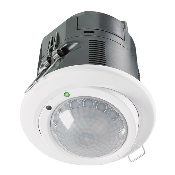
LightSpot HD Dimming PIR Sensors
Only suitably qualified personnel should install this equipment
Installing the Sensor into Ceiling Tile
73mm
1
2
Electrical Connections
Cable clamps can
be reversed to
reduce aperture
Channel D0
(QuickLink
connection)
Mains supply
and Channel S1
fig 2
Part Number
LS3000AR
●
●
LS3000D
●
LS3000DR
●
●
LS3243R
●
●
LS3043AR
●
●
●
LS3043DR
●
●
●
LS3000ARMB
●
●
LS3000DMB
●
LS3000DRMB
●
●
LS3000ARHB
●
●
LS3000DHB
●
LS3000DRHB
●
●
LS3243RMB
●
●
LS3043DRMB
●
●
●
LS3243RHB
●
●
LS3043DRHB
●
●
●
Add suffix F for flush mount or SM for surface mount
Removing the Terminal Cover
1
2
The following wiring diagrams show how to connect some of the more
fully-featured products listed in the product table above. For clarity, the wiring
for some of the lesser-featured products is not shown, but the wiring principles
are the same and equally applicable. Simply omit any sections that are not
relevant to the product being installed.
Two-Channel Application, One Channel Switching,
One Channel Digital Dimming (fig 3)
NOTE:
1. Digital ballasts are normally
wired from an unswitched
supply.
2. The sensor will
automatically adjust to
control DSI or DALI
ballasts, but all ballasts
must be of the same type.
Switch
SW1
Channel
SWITCHING
S1
LUMINAIRES
Channel D1
D
DIGITAL BALLAST
D
D
DIGITAL BALLAST
D
MORE
Digital Dimming
Luminaires Channel D1
Positioning the Sensor
●
●
●
●
●
●
●
●
●
●
●
●
●
●
●
●
●
●
●
●
●
Macro
High Sensitivity Micro Detection
●
●
Detection
Fixing to Ceiling – Standard Method
1
2
Single Channel Dimming Using Analogue
or Digital Ballasts (fig 4)
Analogue ballasts cannot be switched off from the control terminals, so it is
necessary to switch the mains power from the sensor as shown in the diagram
below. Although switching the mains power is not necessary with digital ballasts,
they may be wired this way in order to reduce the quiescent power consumption
in unoccupied areas to an absolute minimum.
Ch D0
Data & Control
LS3043DR
IEC 60669-2-1
Digital Dimming
+ _
230VAC 15%
Ch S1
Ch D1
50-60Hz
SW
Lout
L
N
Switch
SW1
L
N
E
Supply
+
L
ANALOGUE BALLAST
–
N
E
+
L
ANALOGUE BALLAST
–
N
E
MORE
Switched Dimming
Luminaires Channel D1
fig 3
The sensor should be positioned on the ceiling in the centre of the occupied
space. This product is available in three different mounting height variants;
see fig.1 and the table below. Ensure that the maximum recommended
mounting height is not exceeded.
h
Avoid mounting next to an AC unit.
For additional information on
positioning please refer to Tilt
and Lock the Sensor, overleaf.
Micro Detection -
Type
High Sensitivity
2.8:1
Office
(7m diameter @ 2.5m height)
Mid Bay
N/A
Macro
High Bay
N/A
Detection
fig 1
Fixing to Ceiling – Secure Lockring Method
(Available separately, please order lockring)
Ceiling tile
1
2
thickness range
1-20mm
Remove spring
Connecting Sensors together with QuickLink,
and Creation of an Additional Dimming Channel (fig 5)
The wiring diagram below shows how to connect sensors together using the
QuickLink Bus. QuickLink is a convenient way of wiring multiple sensors so
that they share information (e.g. occupancy) and are able to work in
harmony. Some sensors operate from a low voltage derived from the
QuickLink bus and therefore do not require a mains connection – this
enables fast and convenient installation. The Low Voltage Bus sensors
are not described in detail here (see QuickLink Bus Sensors Installation
Instructions for further information). It is permissible to connect up to four
sensors together in this way. No more than two mains-powered sensors
Ch D0
are allowed in a common connection.
Data & Control
LS3043AR
IEC 60669-2-1
Analogue Dimming
230VAC 15%
+ _
Ch S1
Ch D1
50-60Hz
SW
Lout
L
N
Ch D0
Data & Control
LS3043DR
Digital Dimming
L
230VAC 15%
+ _
Ch S1
50-60Hz
SW
Lout
L
N
N
E
Supply
L
N
Switch
E
SW1
L
N
E
SWITCHING
LUMINAIRES
fig 4
Channel S1
The sensor is more sensitive
to movement across the beam
compared with movement
towards the centre.
Aspect ratio
(diameter : height)
Macro Detection -
Max recommended
Standard Sensitivity
mounting height
4:1
3.5m
(10m diameter @2.5m height)
2:1
12m
(20m diameter @10m height)
1.9:1
16m
(27m diameter @14m height)
Ratchet Component x4
3
2
3
1
4
Ceiling tile
thickness range
1-20mm
NOTE: To remove sensor
Ratchet
rotate Lockring and
moulding
pull up
QuickLink Bus
Internally Looped
To next
sensor
Ch D0
D D
Loop in
D
D
Ch D0
Data & Control
Loop Out
LS3260
IEC 60669-2-1
Low voltage
IEC 60669-2-1
Ch D1
L
N
E
Supply
DIGITAL
DALI
DIMMING
DIMMING
LOAD
LOAD
fig 5
Channel D1
Channel D0
Advertisement
Table of Contents

Related Manuals for Ex-Or LS3000AR

Summary of Contents for Ex-Or LS3000AR
- Page 1 This product is available in three different mounting height variants; Part Number see fig.1 and the table below. Ensure that the maximum recommended mounting height is not exceeded. LS3000AR ● ● ● Avoid mounting next to an AC unit.
- Page 2 Cut the Function NOTE: Please go to www.ex-or.com for a complete list of Channel D0 or Channel D1 error – e.g. mask segment(s) as desired and install by pushing the mask lip between the programmable parameters.
Need help?
Do you have a question about the LS3000AR and is the answer not in the manual?
Questions and answers