
Related Manuals for Bolton Tools BS-128DR


Summary of Contents for Bolton Tools BS-128DR
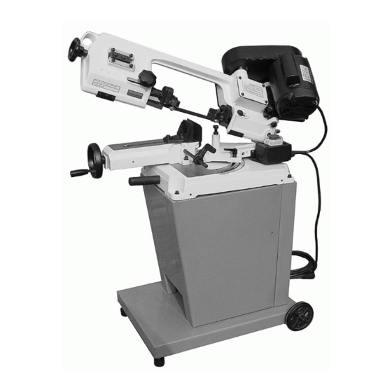
- Page 1 Horizontal and Vertical Metal Cutting Band Saw OPERATION MANUAL MODEL: BS-128DR BS-128HDR...
- Page 2 SAFETY 1. Know your bandsaw. Read the operator’s Manual carefully. Learn the operations, applications and limitation as well as the specific potential hazards peculiar to this band saw. 2. This unit is equipped with a three-prong (grounded) plug for your protection against shock hazards and should be plugged directly into a property grounded three-prong receptacle.
-
Page 3: Tell Tale Chips
A guard or other part that is damaged should be properly repaired or replaced. 20. When moving the saw, ALWAYS have the head lowered to the horizontal position. SPECIFICATION: Model BS-128DR BS-128HDR Motor 1/3 OR 1/2HP Blade size 12.7x0.64x1638mm... - Page 4 Burned heavy Chips-reduce feed rate and/or band speed. Curly silvery and warm chips-optimum Feed rate and band speed. ASSEMBLY A 1/3 or 1/2 HP motor split phase or capacitor start is recommended for best economical performance. Counter clockwise is required. Note that rotation can be reversed by following directions given on terminal or name plate.
- Page 5 depression in the belt when applying pressure with your thumb. 12. Tighten the head screw holding the motor mounting plate to the guard plate. 13. Connect the electrical harness to the motor terminal box. The motor should be protected with a time delay fuse or circuit breaker with a rated amperage slightly greater than the full-load amperage of the motor.
-
Page 6: Blade Direction Of Travel
Mild steel, hard brass Medium Medium or bronze Aluminum plastic Large Small BLADE DIRECTION OF TRAVEL Be sure the blade is assembled to the pulleys such that the vertical edge engages the work piece first. STARTING SAW Switch button function description (FOR CE ONLY) CAUTION: NEVER OPERATE SAW WITHOUT BLADE GUARDS IN PLACE. -
Page 7: Blade Guide Bearing Adjustment
4. Remove left hand from bottom pulley and place it at the top aide of the blade to continue the application on the upward pull on the blade. 5. Remove right hand from blade and adjust the position of the top pulley to permit left hand to slip the blade around the pulley using the thumb index and little finger as guides. -
Page 8: Adjusting Blade Tension
ADJUSTING BLADE TENSION 1. Make sure the motor is shut off. 2. Press the blade lightly with left hand, make the rear blade against the flange of blade wheel and test the blade tension. Adjusting Blade Tension 3. Adjust the blade tension adjustable knob with the right hand until the blade obtain the proper tension. -
Page 9: Maintenance
D. Tighten the screw #11. Adjusting the blade MAINTENANCE CAUTION: MAKE CERTAIN THAT THE UNIT IS DISCONNECTED FROM THE POWER SOURCE BEFORE ATTEMTING TO SERVICE OR REMOVE ANY COMPONENT! LUBRICATION Lubricate the following components using SAE-30 oil as noted. 1. Ball-bearing none. 2. -
Page 10: Troubleshooting Chart
TROUBLE SHOOTING CHART Symptom Possible Cause (s) Corrective Action Material loose in vise 1. Clamp work securely Incorrect speed or feed 2. Adjust speed or feed Blade teeth spacing too 3. Replace with a small teeth Excessive Blade large spacing blade Breakage Material too coarse 4. - Page 11 Symptom Possible Cause (s) Corrective Action 1. Tooth too coarse for work 1. Use finer tooth blade 2. Too heavy pressure, too 2. Decrease pressure, slow speed increase speed Teeth Ripping from Blade 3. Vibrating work piece 3. Clamp work piece 4.
-
Page 12: Parts List
PARTS LIST Part Part Description Qty. Description Qty. Hex. Head screw Motor mount plate Hex. nut Motor Spring washer Motor pulley Washer Oil seal Wheel (option) Worm gear assembly Hex. Head screw Gear box gasket Hex. nut Gear box cover Motor cable Worm gear shaft assembly Pivoting rod... - Page 13 Hex. Head screw Hex. Nut Cylinder assembly Balancing bracket Cylinder upper support Flat washer Hex. Socket headless screw Hexagon head screw Hex. Head screw Flat briquette Spring washer Screw rod Hex. Socket head screw Balancing spring Vise jaw bracket (rear) Vise jaw bracket (front) Built-in shelf (option) Wall plate...
Need help?
Do you have a question about the BS-128DR and is the answer not in the manual?
Questions and answers