Table of Contents
Advertisement
Advertisement
Table of Contents

Related Manuals for Bolton Tools GK-4235


Summary of Contents for Bolton Tools GK-4235
- Page 1 METAL CUTTING BAND SAW MODEL: GK-4235 Operation manual Table of contents...
-
Page 2: Table Of Contents
1. Safety ........................1 2. Specification ......................4 3. Identification ......................5 4. Set up ........................7 4.1 Moving & placing base unit ................7 4.2 Clean up ......................8 4.3 Work stop ....................... 8 4.4 Test run ......................9 5. -
Page 3: Safety
1. SAFETY Warning! This manual provides critical safety instruction on the proper setup, operation, maintenance and service of this machine. Failure to read, understand and follow the instruction given in this manual may result in serious personal injury, including amputation, electrocution or death. The owner of this machine is solely responsible for its safe use. - Page 4 permanent hearing damage. 11. Wear proper apparel. Don’t wear loose clothing, gloves, neckties, rings, or jewelry which may get caught in moving parts. Wear protective hair covering to contain long hair and wear non-slip footwear. 12. Never operate machinery when tired, or under the influence of drugs or alcohol. Be mentally alert at all times when running machinery.
- Page 5 designed. 29. Secure workpiece. Use clamps or a vise to hold the workpiece when practical. A secured workpiece protects your hands and frees both hands to operate the machine. 30. Don’t overreach. Keep proper footing and balance at all times. 31.
-
Page 6: Specification
with the machine OFF and the power disconnected to the machine. Wait for all moving parts to come to a complete stop. 47. Hot surfaces, due to friction, the workpiece, chips and some machine components can be hot enough to burn you. 2. -
Page 7: Identification
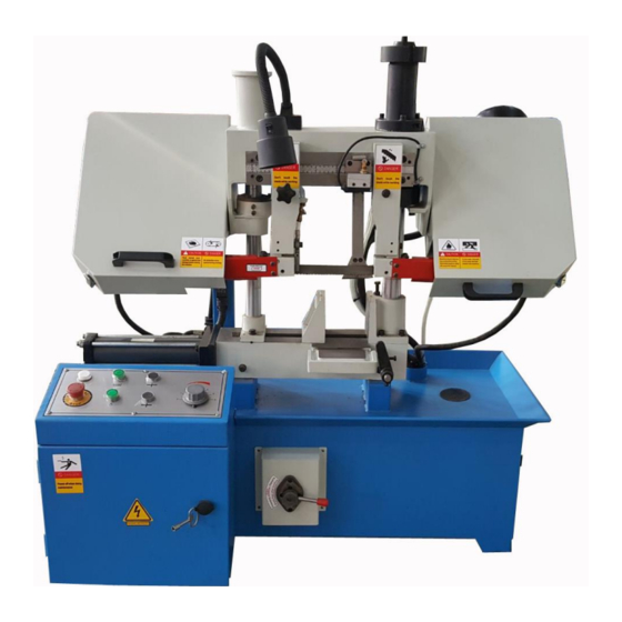
3. IDENTIFICATION Figure 1 A. Saw frame I. Coolant valve controls B. Arm J. Coolant pan C. Light K. Work stop D. Blade guide scale L. Vise clamping (optional) E. Quick feeder M. Control panel F. Column N. Electric box G. -
Page 8: Control Panel
Control panel Figure 2 A. Power light: when light, indicates that system is energized and machine is ready to operate. B. Start: press this button, the machine can start working. C. Saw frame up: press this button, the saw frame will go up until it touch the top limit point. -
Page 9: Set Up
Blade speed switch: Usually we use two speeds motor, so TGK-4220 has two blade speeds. You can change blade speed by this switch. For optional: we can supply servo motor, then you can change blade speed variable. You can change the blade speed by the speed rate dial on panel A. -
Page 10: Clean Up
Please install the machine on the horizontal ground. Although not required, we recommend that you mount your new machine to the floor. 4.2 Clean up The unpainted surfaces are coated with a waxy oil to protect them for corrosion during shipment. -
Page 11: Test Run
4.4 Test run Starting the machine: (1) Read the entire instruction manual. (2) Make sure all tools and foreign objects have been removed from the machine. (3) Put on safety glasses and secure loose clothing or long hair. (4) Connect the band saw to power. (5) Raise the band saw and close the feed control knob to keep the saw in place. -
Page 12: Vise
Our band saws have 3 types clamping system, to ensure that you can hold the workpiece tightly. (1) Raise the bow to the maximum height and lock in place. (2) Clamping the workpiece by hand wheel or hydraulic cylinder A: You clamp the workpiece by the hand wheel as picture 5. Hand wheel Figure 5 B: It has a small hydraulic cylinder to tighten the vise, you need to clamp the workpiece by... -
Page 13: Coolant System
C: It has a long hydraulic cylinder for clamping, you can tighten the vise by the vise clamping handle, as picture 7. long hydraulic cylinder vise clamping handle Figure 7 5.2 Coolant system Our band saw has a built-in coolant system that extends the life of your band saw blades by lowering the temperature of the blade and workpiece. -
Page 14: Cutting Fluid
(5) Turn the coolant pump on before making your cut. (6) Monitor the coolant level frequently to keep the system working properly, to ensure the oil is above top water level, you had better is in 2/3 top water level. Note: Coolant pump can’t working without coolant oil, or will damage the pump. -
Page 15: Blade Selection
Knob Guide block Figure 9 5.5 Blade selection Selecting the right blade for the job depends on a variety of factors, such as the type of material being cut, hardness of the material, material shape, machine capacity, and operator technique. We suggest you do some research for your specific situation so you get the best blade to match your needs. -
Page 16: Blade Speed
5.6 Blade speed Please adjust proper feeding distance and speed according to material and shape. Usually our TGK-4220/TGK-4235/TGK-4240 have two blade speeds, of course, we can use a servo motor, then you can change blade speed by speed adjustment knob. Note: only change speeds while the motor is running. -
Page 17: Telltale Chips
switch, the bow will stop raising. (see figure 10) 2. Set the feed rate dial to the desired feed rate. Range is from 1 being slowest to 6 being fastest. We have a optional accessory: quick feed. The quick feed is a little lower than blade, the bow will feed down quickly with quick feed, when the quick feed touch the cutting material, the bow will feed down according to the feed rate which you set. -
Page 18: Blade Tension
Burned heavy chips: reduce feed rate and/or blade speed. Curly silvery and warm chips: optimum feed rate and blade speed. 5.9 Blade tension Proper blade tension is essential to long blade life, straight cuts, and efficient cutting. Our band saw feature a blade tension to assist you with blade tensioning. Two major signs that you don’t have proper blade tension are: (1) the blade stalls in cut and slips on the wheels;... -
Page 19: Manual Workpiece Feeder
5.10 Manual workpiece feeder Maybe some customers want to cut big & heavy material, it will be difficult to feed the material by hand, so our TGK-4235 has a manual workpiece feeder, you can feed the workpiece by the hand wheel easily. The detail operation information as below: (1) Put the workpiece onto the roller (see figure 14). - Page 20 B. Damaged saw blade C. Worn or damaged wires D. Any other unsafe condition E. Clean after each use: Please clean the chip on time and carefully, otherwise it will block the blade tooth, influence cutting result and blade using life. F.
-
Page 21: Hydraulic System
7. HYDRAULIC SYSTEM Please check the oil is enough by fluid, if the oil is not enough, please inject the hydraulic oil. For example, please use #46 hydraulic oil in summer and #32 hydraulic oil in winter. Turn on the oil pump to make the clamping cylinder to the clamping position, system pressure to 2.5 Mpa. -
Page 22: Trouble Shooting
8. TROUBLE SHOOTING Symptom Possible Cause (s) Corrective Action 1. Material loose in vise 1. Clamp work securely 2. Incorrect speed or feed 2. Adjust speed or feed 3. Blade teeth spacing too large 3. Replace with a small teeth 4. - Page 23 Symptom Possible Cause (s) Corrective Action Unusual Wear 1. Blade guides worn 1. Replace on Side/Back of 2. Blade guide bearings not 2. Adjust as per operators manual blade adjusted properly 3. Tighten 3. Blade guide bearing bracket is loose 1.
- Page 24 Symptom Possible Cause (s) Corrective Action Bad Cuts 1. Too much speed or feed 1. Decrease speed or feed (Rough) 2. Blade is too coarse 2. Replace with finer blade 3. Blade tension loose 3. Adjust blade tension Blade is twisting 1.
-
Page 25: Electrical Drawing & Breakdown/Part List
9. Electrical drawing & breakdown/part list... - Page 26 9.2 Electric drawing TGK-4235/TGK-4240...
- Page 28 9.2 Breakdown TGK4235...
- Page 30 Part list TGK4235 Part No. Description Part No. Description Reducer Right bearing bracket Flange plate Roll pin 10x55 Washer Cap screw M10x30 Slotted set screw with Hex bolt M12x45 flat point M6X12 Nut M12 Nut M6 Lock washer 12 Hex bolt M6x35 Right blade cover Right arm Bracket for blade...
- Page 31 Part No. Description Part No. Description Shaft Control plate Left cover Plate Cap screw M8x25 Electric box Nut M8 Cap screw M6x20 Left cover Panel Seat Door Cap screw M5x12 Lock Washer 10 Side plate Cap screw M10x25 Cylinder for clamp Connector Hex bolt M10x45 Up/down cylinder...
-
Page 32: Tgk4235
Part No. Description Part No. Description Big washer 6 Cap screw M8x16 Screw M6x8 Cover Hand wheel ¢125x¢15 Back cover Key 5x15 Bolt M10x1 ¢1.8x¢9.5 External retaining ring 17 O Ring Shaft Pump Bearing 61803-2Z Bolt M5x10 Worm shaft Stand Pin 4x22 Front plate Slight glass for...
Need help?
Do you have a question about the GK-4235 and is the answer not in the manual?
Questions and answers