Advertisement
Quick Links
Advertisement

Related Manuals for Bolton Tools VS-400


Summary of Contents for Bolton Tools VS-400
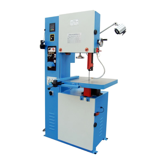
- Page 1 THE VERTICAL BAND SAW MODEL VS-400 Assembly & Operating Instruction...
- Page 2 1. INTRODUCTION This operation instruction manual conforms to the requirements of the 98/37/EEC Machine Directives and subsequent amendments. In the light of this,special attention has been given to safety aspects and accident prevention in the work-place for each stage in the machine’s “life”. Information which could be of particular assistance to the operator has been highlighted.
- Page 3 Code of any relevant drawings ● Requests for compensation for the inactivity of the machine will not be accepted. ● The guarantee does not cover uses which are not in line with these operating instructions which are an integral part of the machine. Nor is maintenance covered if the instructions supplied are not observed.
- Page 4 Description of routine maintenance Chap. 10 Information regarding environmental noise Chap. 11 List of spare parts Chap. 12 Laying off-Demolition 3.2 INDEX OF DRAWINGS,DIAGRAMS AND TABLES ENCL.TYPE DESCRIPTION ENCL NO. CHAP Table Cutting capacity-Selection blade-cutting speeds-Installation plan Drawings Handling and transportation Drawings Blade guides-Blade guide bearings Drawings...
- Page 5 aspects-design principles. - EN 983 1996 Safety requirements related to systems and components for hydraulic and pneumatic transmissions. - EN 1037 1995 Safety of machinery. Isolation and energy dissipation. Prevention of unexpected start-up. EN 1088 1995 Safety of machinery- Interlocking devices with and without guard- locking.
- Page 6 button and a START button. The control lever,fitted with an ergonomic hand-grip and activation button with safety release action, reduces fatigue during operation to a minimum. The blade is protected by a guard with interlock which covers the upper area and the hand wheels and by two adjustable lower guards which protect the operator from ejected shavings and coolant.
- Page 7 E. Welder F. Grinder G. Blade installation H. Guide rob adjustment I. Inverter speed selection J. Air pump K. Angle cutting L. Safety and maintenance M. Inverter parameters ACTION TAKEN A. Power 1. First, before operating the machine, be sure to check the voltage which is in accordance with the power supply system.
- Page 8 3. When cutting ‘Radius’ – the smaller the ‘Radius’ the narrower the blade. 4. Refer to the Speed & Pitch Selector guide on the machine for proper radius and pitch. D. Blade cutting Device: Use the Blade cutter only for cutting blades if you want to maintain the cutter for a long period of time.
- Page 9 K. Air pump: Voltage: 220V/60HZ Current: 0.5mA Flow rate:10-12(L/min) Pressure: 0.20Kg/cm2 Type of fluid: Air L. Angles Cutting: 1. Declination sawing: Loose table nuts; adjust the table into the desirable position, and retighten the nuts. “R” shape sawing: Turn slowly because the sawing edge must remain flat, straight and smooth.
- Page 10 take away the chips, and slightly lubricate the surface of the machine and all joints to keep them from rusting. N. INVERTER PARAMETER: (1) Consumers allowed adjust parameters without authorization .(In case that machine failure is caused by any consumer who alters any parameter without authorization, the consumer should be responsible for the failure.) (2) Inverter parameters are only provided for the qualified technician.
- Page 11 4. Push the welding button (green) so as to start welding operation. Notes: During welding process, wear goggles and keep away from flammable material because spark may be caused during the operation. 5. Loosen the handle for clamping saw blade, and then turn the pressure regulator counterclockwise to position “0”.
- Page 12 V400-1003 Up door GB/T6170 Nut M16 Blade weld GB/T96 Big washer 8 GB/T818 Bolt M5X10 54.1 GB/T6170 Nut M8 GB/T70.1 Bolt M8X16 GB/T77 Bolt M8X16 Blade cutter GB/T5783 Bolt M8X35 GB/T818 Bolt M5X10 GB/T818 Bolt M5X8 Transducer V400-3014 Finger display Transducer small V400-1020 V400-3017...
- Page 13 3X24 丝杆 V400-5011 Washer V400-4004 V400-5010 Bolt washer GB/T5783 Bolt M8X25 V400-5007 Slanting gear GB/T95 Washer 8 V400-5006 Shaft bolt V400-4019 Shaft seat Handle φ80Xφ10 V400-4006 Up wheel seat V400-5008 Screw V400-4011 Right wash board V400-5003 Washer V400-4003 Up wheel seat Elasticity pin V400-5001 Up guard seat...
- Page 14 24(4) 25(4) 27(4) 28(4) 18(4) 16(2) 15(6) 31(4) 34(2) 36(10) 37(10) 11(4) 9(2) 6(4) 5(4) 3(2) 4(4) 2(2) 38(2) 39(2)
- Page 15 96(2) 87 88 89 90 85(2) 84(2) 75(2) 82(2) 79(4) 78(4) 73(4) 72(4) 66(2) 65(2) 60(4) 47(2) 46(2) 48(2) 45(2) 44(4) 43(4) 42(4) 56(4) 55(4) 54(8) 45.1(2) 54.1(4)
- Page 16 131.1 133(4) 134(4) 137(2) 127(2) 126(2) 124(2) 123(2) 122(2) 112(2) 117(4) 116(4) 119(2) 120(2) 111(2) 110(4) 115.1(3) 108(2) 99.1(2) 97(3) 106(2) 101(4) 102(4) 104(2) 105(2)
- Page 17 VII THE ELECTRICAL DRAWING FOR VS-400 0.7 5m m S Q2 S Q1 SA 1 FU 6 L1 1 L2 1 L3 1 K M 1 F U4 KM 2 S B 1-1 S B 2 FU 7 FU 5...
Need help?
Do you have a question about the VS-400 and is the answer not in the manual?
Questions and answers