Table of Contents
Advertisement
Quick Links
FCC / IC
En
This device complies with part 15 of the FCC and Industry Canada license-exempt RSS standard(s).
Operation is subject to the following two conditions:
(1) this device may not cause harmful interference, and (2) this device must accept any
interference received, including interference that may cause undesired operation.
FCC NOTE: The manufacturer is not responsible for any radio or TV interference caused by
unauthorized modifications to this equipment. Such modifications could void the user's authority
to operate the equipment.
NOTE: This equipment has been tested and found to comply with the limits for a Class B digital
device, pursuant to Part 15 of the FCC Rules. These limits are designed to provide reasonable
protection against harmful interference in a residential installation. This equipment generates,
uses and can radiate radio frequency energy and, if not installed and used in accordance with
the instructions may cause harmful interference to radio communications. However, there is no
guarantee that interference will not occur in a particular installation. If this equipment does cause
harmful interference to radio or television reception, which can be determined by turning the
equipment off and on, the user is encouraged to try to correct the
interference by one or more of the following measures:
— Reorient or relocate the receiving antenna.
— Increase the separation between the equipment and receiver.
— Connect the equipment into an outlet on a circuit different from that to which the receiver is
connected.
— Consult the dealer or an experienced radio/TV technician for help
Important note: To comply with the FCC RF exposure compliance requirements, no change to
the antenna or the device is permitted. Any change to the antenna or the device could result in
the device exceeding the RF exposure requirements and void user's authority to operate the device.
Fr
Cet appareil est conforme au paragraphe 15 des normes FCC et au CNR pour les appareils
exempts de licence d'Industrie Canada. Son utilisation est sujette aux deux conditions suivantes :
1) cet appareil ne doit pas occasionner de brouillage préjudiciable et 2) cet appareil doit accepter
toutes les interférences reçues, notamment les interférences qui peuvent provoquer un
fonctionnement non désiré.
NOTE DE LA FCC : Le fabricant n'est pas responsable des interférences sur les fréquences
radioélectriques ou télévisuelles pouvant être causées par des modifications non autorisées de ce
matériel. De telles modifications peuvent annuler le droit de l'utilisateur à utiliser cet appareil.
REMARQUE : Cet appareil a été testé et certifié conforme aux limites relatives aux appareils
numériques de catégorie B définies dans le paragraphe 15 des normes FCC. Ces limites ont été
définies afin de fournir une protection raisonnable contre le brouillage préjudiciable en milieu
résidentiel. Cet appareil produit, utilise et peut émettre des ondes de fréquence radio et, s'il n'est
pas installé et utilisé conformément aux instructions, il peut provoquer un brouillage préjudiciable
aux communications radio. Il n'existe toutefois aucune garantie que des interférences ne se
produiront pas au sein d'une installation donnée. Si cet appareil occasionne un brouillage
préjudiciable à la réception radiophonique ou télévisuelle, il suffit d'allumer et d'éteindre l'appareil
pour déterminer sa responsabilité. Nous encourageons l'utilisateur à essayer de corriger ces
interférences en appliquant une ou plusieurs des mesures suivantes :
— Réorienter ou déplacer l'antenne de réception.
— Augmenter la distance entre l'appareil et le récepteur.
— Brancher l'appareil à une prise secteur différente de celle du récepteur.
— Consulter le revendeur ou un technicien spécialisé en postes radio ou téléviseurs.
Remarque importante : Pour se conformer aux exigences de conformité de la FCC concernant
l'exposition aux RF, aucune modification apportée à l'antenne ou au dispositif n'est autorisée. Toute
modification apportée à l'antenne ou au dispositif pourrait faire en sorte que le dispositif dépasse
les exigences d'exposition aux RF et pourrait annuler le droit de l'utilisateur à utiliser ce dispositif.
Es
Este dispositivo cumple con las Especificaciones del apartado 15 de las normas de la FCC y con
las especificaciones de las normas radioeléctricas (RSS) del Ministerio de Industria de Canadá
aplicables a aparatos exentos de licencia. El funcionamiento está sujeto a las siguientes dos
condiciones: (1) este dispositivo no debe provocar interferencia perjudicial, y (2) este dispositivo
debe aceptar toda interferencia que reciba, incluso la que pudiera causar un funcionamiento no
deseado.
NOTA DE LA FCC: El fabricante no se hace responsable de ninguna interferencia de radio o TV
ocasionada por modificaciones no autorizadas efectuadas a este equipo. Dichas modificaciones
podrían anular la autoridad del usuario para utilizar el equipo.
NOTA: Este equipo ha sido probado y cumple con los límites para aparatos digitales de Clase B,
de conformidad con el apartado 15 de las normas de la FCC. Estos límites están diseñados para
proveer protección razonable contra interferencias perjudiciales en una instalación residencial.
Este equipo genera, usa y puede irradiar energía de radiofrecuencias y, si no se instala y usa según
las instrucciones, puede provocar interferencia perjudicial a las radiocomunicaciones. No obstante,
no hay garantías de que no ocurrirá interferencia en una instalación en particular. Si este equipo
provoca interferencia perjudicial a la recepción de radio o televisión, lo que puede determinarse
encendiendo y apagando el equipo, se recomienda que el usuario intente corregir la
interferencia por medio de la implementación de una o más de las siguientes medidas:
— Reorientar o reubicar la antena receptora.
— Incrementar la separación entre el equipo y el receptor.
— Conectar el equipo a un tomacorriente de un circuito diferente del circuito al que está
conectado el receptor.
— Consultar al distribuidor o a un técnico con experiencia en radio/televisión para
solicitar asistencia.
Nota importante: Para cumplir con los requisitos de cumplimiento de exposición de
radiofrecuencia de la FCC, no se permiten cambios a la antena o el dispositivo. Cualquier cambio a
la antena o dispositivo podría hacer que el dispositivo supere los requerimientos de exposición de
radiofrecuencia y anular la autoridad del usuario para operar el dispositivo.
FCC — U2ZZW4004 | IC: 6924A-ZW4004
Jasco Products Company | Model: ZW4004 / 12726
CAN ICES-3(B) / NMB-3(B)
All brand names shown are trademarks
MADE IN CHINA/FABRIQUÉ EN CHINE/HECHO EN CHINA
of their respective owners.
GE IS A TRADEMARK OF GENERAL ELECTRIC COMPANY
Tous les noms de marque illustrés sont
AND IS UNDER LICENSE BY
des marques de commerce de leurs
JASCO PRODUCTS COMPANY LLC,
propriétaires respectifs.
10 E. MEMORIAL RD.,
Todas las marcas que aparecen aquí
OKLAHOMA CITY, OK 73114.
son marcas registradas de sus
© JASCO 2016 | 12726 | ZW4004 | rev. 021/19/16 DA
respectivos dueños.
1.
Tools You Will Need
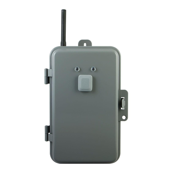
Getting To Know Your New Z-Wave Device
• Operation mode switch allows operation without requiring Z-Wave network
• Remote ON/OFF control via the Z-Wave controller, on mobile devices
• Manual override ON/OFF control with the exterior-mounted pushbutton
• Weather resistant, rainproof housing; suitable for use outdoors in damp or wet conditions
• Lockable tamper resistant metal case ensures secure connection and keeps dirt & debris out
• Energy monitoring capability allows remote monitoring of Watts and Kilowatt hours with
compatible systems
2.
A
B
C
D
A. Indicator Lights
RED light indicates AC power "ON"
GREEN light indicates connected device power "ON"
B. Manual Override Button
Single press — turn the connected device(s) On/Off when
Operation Mode Switch is set to "Z-Wave"
C. Operation Mode Switch
On — When set to "
" icon, the connected device has
continuous power. Z-Wave control is disabled.
Off — When set to "
" icon, the connected device has no
power. Z-Wave control is disabled.
Z-Wave — When set to "
" icon, the connect device has
continuous power. Z-Wave control is enabled.
D. Connection Terminal
Z-WAVE INTEROPERABILITY
This product can be included and operated
in any Z-Wave network with other Z-Wave
certified devices from other manufacturers
and/or other applications. All non-battery
operated nodes within the network will
act as repeaters regardless of vendor to
increase reliability of the network.
MANUAL • MANUEL •
MANUAL
Direct Wire
Indoor/Outdoor
Smart Switch
À Raccordement Direct
Intérieur/Extérieur
Interrupteur Intelligent
Cable Directo
Para Interiores/Exteriores
Interruptor Inteligente
Scan to view
installation guide
Balayez ce code pour
consulter le guide
d'installation.
Escanear para ver
la guía de instalación
Z-Wave® Certified Wireless Lighting Control
Certifié Z-Wave Commande d'éclairage sans fil
Control inalámbrico para iluminación certificado por Z-Wave®
3.
1/2"
3/4"
Pre-installation
Before you start, follow the instructions below to remove knockouts in order to route wiring to connection
terminals. Knockouts may be made 1/2" or 3/4".
For 1/2" knockout:
1. Place small blade screwdriver into inner ring of knockout circle as pictured above.
2. Tap down lightly with the screwdriver in order to punch the 1/2" knockout loose.
For 3/4" knockout:
1. Create 1/2" Knockouts as instructed.
2. With pliers, grip outer ring of knockout circle as pictured above.
3. Gently twist and pull in order to remove outer ring and form 3/4" knockout.
5.
240 VAC - Single Load Energy Monitored
1
2
3
4
5
6
Line 1
Load Line 1
Jumper
Line 2
Load Line 2
Green/Bare
Ground
Terminal 1: 240V Line 1
Terminal 4: Load Line 2
Terminal 2: 240V Line 2
Terminal 6: Load Line 1
Terminal 3/5: Jumper connection
between Terminals
For proper wiring connections:
1. Strip ½" of insulation covering wires
2. Tighten all screw terminals to 25 lbf-in.
Note: Improper tightening can cause overheating and equipment failure.
Warning! Turn off power to the switch at the service panel. Refer to 'Warning – Shock Hazard'
above.
1. Open metal enclosure door. Raise plastic guard covering terminals 1-6.
2. Input voltage connection
a. Connect 240VAC Line 1 (black) to Terminal 1.
b. Connect 240VAC Line 2 (black) to Terminal 2.
c. Connect ground wire (green/bare) to ground terminal.
3. Jumper connection
Connect jumper wire between terminals 3 and 5.
4. Load connection
a. Connect Load Line 1 (black) to Terminal 4.
b. Connect Load Line 2 (black) to Terminal 6.
c. Connect ground wires (green/bare) to ground terminal.
5. Lower plastic guard covering terminals 1-6. Close metal enclosure door.
6. Connection check
a. After 24 hours, disconnect power to module and check the connections.
b. Open metal enclosure door. Raise plastic guard covering terminals 1-6.
c. Verify that all screws/connections are securely tightened.
7. Lower plastic guard covering terminals 1-6. Close metal enclosure door.
IMPORTANT: Always close rain-proof door after use.
6.
DO NOT RETURN THIS
PRODUCT TO THE STORE
STOP
NE RETOURNEZ PAS
CE PRODUIT AU MAGASIN
NO DEVUELVA ESTE
PRODUCTO A LA TIENDA
If you have any problems or questions, contact our tech support team
at; 1-800-654-8483, option 1 Monday–Friday, 7:30–5pm CST
For the most up-to-date product support, accessories, electronic (PDF) format
manuals and more, visit www.jascoproducts.com/support.
• No user servicable parts in this unit.
Si vous avez des problèmes ou des questions, communiquez avec notre
équipe de soutien technique au 1-800-654-8483, option1, du lundi au vendredi,
de 7 h 30 à 17 h (HNC).
Pour le soutien relatif aux produits le plus à jour, les accessoires,
les manuels en format électronique (PDF) et plus encore, visitez le site
www.jascoproducts.com/support.
• Aucune des pièces de ce dispositif ne peut être réparée par l'utilisateur.
Si tiene problemas o dudas, comuníquese con nuestro equipo técnico al número:
1-800-654-8483, opción 1 de lunes a viernes, de 7:30 a 5 p.m., hora estándar del
centro (CST).
Para recibir el soporte técnico más actualizado sobre productos,
accesorios, manuales en formato digital (PDF), entre otros,
visite www.jascoproducts.com/support.
• Esta unidad no contiene piezas que el usuario pueda reparar.
WARNING
• RECOMMEND INSTALLATION BY LICENSED
• SE RECOMIENDA QUE LA INSTALACIÓN LA
ELECTRICIAN.
REALICE UN ELECTRICISTA AUTORIZADO.
CAUTION:
PRECAUCIÓN:
• RISK OF ELECTRIC SHOCK — MORE THAN ONE
• RIESGO DE DESCARGA ELÉCTRICA — PUEDE
DISCONNECT SWITCH MAY BE REQUIRED TO DE-
QUE SEA NECESARIO DESCONECTAR MÁS
ENERGIZE THE DEVICE BEFORE SERVICING.
DE UN INTERRUPTOR PARA DESENERGIZAR
• HIGH VOLTAGE (THERE MAY BE MORE THAN ONE
EL DISPOSITIVO ANTES DE REALIZAR EL
SOURCE OF SUPPLY) DISCONNECT ALL POWER
MANTENIMIENTO.
SOURCES BEFORE SERVICING.
• ALTA TENSIÓN (ES POSIBLE QUE HAYA MÁS DE
• USE COPPER CONDUCTORS ONLY
UNA FUENTE DE ENERGÍA), DESCONECTE TODAS
• CLOSE THE COVER AFTER USE
LAS FUENTES DE ENERGÍA ANTES DE REALIZAR EL
• TIGHTEN CONNECTIONS TO 25 LBF-IN.
MANTENIMIENTO.
• USE CORRECT GAUGE WIRE (8-14 AWG) BASED
• USE SÓLO CONDUCTORES DE COBRE
ON LOCAL ELECTRICAL CODE OF AT LEAST 80°C
• CIERRE LA TAPA DESPUÉS DE USAR
RATING (SINGLE CORE IN 8 AWG)
• APRIETE LAS CONEXIONES A 25 LBF-IN.
• RAINTIGHT, APPROVED FOR OUTDOOR USE
• USE CABLE DEL CALIBRE CORRECTO (8-14
• WIRE STRIP LENGTH 1/2"
AWG) TENIENDO COMO BASE EL CÓDIGO DE
• GROUNDING: NATIONAL ELECTRICAL CODE
NORMAS DE ELECTRICIDAD LOCAL DE UN
REQUIRES THAT GROUNDING MUST BE
RÉGIMEN NOMINAL DE AL MENOS 80 °C (CABLE
CONTINUOUS AND IN PROPER ELECTRICAL
MONOCONDUCTOR DE 8 AWG)
CONTACT IN ALL GROUNDING CONDUCTORS,
• IMPERMEABLE, APROBADO PARA USO EN
METALLIC CONDUITS AND GROUNDING
EXTERIORES
TERMINALS.
• LONGITUD DE CABLE SIN AISLAMIENTO 1/2"
• CONEXIÓN A TIERRA: EL CÓDIGO
AVERTISSEMENT
ESTADOUNIDENSE DE NORMAS DE ELECTRICIDAD
EXIGE QUE LA PUESTA A TIERRA SEA CONTINUA,
• INSTALLATION EFFECTUÉE PAR UN ÉLECTRICIEN
CON EL CONTACTO ELÉCTRICO ADECUADO EN
QUALIFIÉ RECOMMANDÉE.
TODOS LOS CONDUCTORES DE PUESTA A TIERRA,
ATTENTION:
LAS CANALETAS METÁLICAS Y LOS BORNES DE
• RISQUE DE CHOC ÉLECTRIQUE – PLUS D'UN
PUESTA A TIERRA.
SECTIONNEUR PEUT ÊTRE NÉCESSAIRE POUR
METTRE L'APPAREIL HORS TENSION AVANT UNE
NOT FOR USE WITH MEDICAL OR LIFE
RÉPARATION.
SUPPORT EQUIPMENT
• HAUTE TENSION (IL PEUT Y AVOIR PLUS D'UNE
Z-WAVE ENABLED DEVICES SHOULD NEVER BE USED TO
SOURCE D'ALIMENTATION), COUPER TOUTES LES
SUPPLY POWER TO, OR CONTROL THE ON/OFF STATUS
SOURCES D'ALIMENTATION AVANT DE PROCÉDER
OF MEDICAL AND/OR LIFE SUPPORT EQUIPMENT.
À LA RÉPARATION.
• UTILISER SEULEMENT DES CONDUCTEURS DE
NE PAS UTILISER AVEC UN ÉQUIPEMENT
CUIVRE.
MÉDICAL OU DE SURVIE
• REFERMER LE COUVERCLE APRÈS L'UTILISATION.
LES DISPOSITIFS COMPATIBLES AVEC LA TECHNOLOGIE
• SERRER LES CONNEXIONS À 25 LBF/PO.
Z-WAVE NE DEVRAIENT JAMAIS ÊTRE UTILISÉS POUR
• UTILISER UN FIL DU BON CALIBRE (8-14 AWG),
ALIMENTER OU COMMANDER LA MISE EN MARCHE OU
D'APRÈS LE CODE DE L'ÉLECTRICITÉ LOCAL, AYANT
L'ARRÊT DE L'ÉQUIPEMENT MÉDICAL OU DE SURVIE.
UNE TEMPÉRATURE NOMINALE D'AU MOINS 80 °C
(FIL UNIPOLAIRE 8 AWG).
SE PROHÍBE SU EMPLEO EN EQUIPO MÉDICO
• ÉTANCHE À LA PLUIE, APPROUVÉ POUR USAGE À
O EQUIPO PARA EL MANTENIMIENTO DE LAS
L'EXTÉRIEUR.
FUNCIONES VITALES
• LONGUEUR DE FIL À DÉNUDER 1/2 PO
• MISE À LA TERRE: SELON LE CODE NATIONAL DE
LOS DISPOSITIVOS Z-WAVE NUNCA SE DEBEN USAR
L'ÉLECTRICITÉ, LA MISE À LA TERRE DOIT ÊTRE
PARA SUMINISTRAR ENERGÍA ELÉCTRICA AL EQUIPO
CONTINUE ET ASSURER UN CONTACT ÉLECTRIQUE
MÉDICO O AL EQUIPO PARA EL MANTENIMIENTO DE
ADÉQUAT SUR L'ENSEMBLE DES CONDUCTEURS
FUNCIONES VITALES, NI PARA CONTROLAR EL ESTADO
DE TERRE, CONDUITS MÉTALLIQUES ET BORNES
DE ENCENDIDO O APAGADO DE DICHOS EQUIPOS.
DE TERRE.
WARNING — SHOCK HAZARD
Turn OFF the power to the branch circuit for the
switch and lighting fixture at the service panel. All
wiring connections must be made with the POWER
OFF to avoid personal injury and/or damage to the
switch.
This device is intended for installation in accordance
with the National Electric Code and local regulations
in the United States, or the Canadian Electrical Code
and local regulations in Canada. If you are unsure
12726
or uncomfortable about performing this installation
ZW4004
consult a qualified electrician.
4.
Choose a suitable mounting location:
Before you start, choose a location for mounting the box with the
following considerations in mind:
• RF Range can be affected by obstructions, metal objects, distance
• Mount in a location with at least 4" of space above unit to allow
• Install upright, in vertical orientation.
Mounting the box for drywall:
1. Hold the box in place and use the three holes (highlighted left) to
2. Drill a 3/16" size hole for the drywall anchors at each marked
3. Insert an anchor in each hole gently tap the open end of anchor
4. Mount the box to the anchors using the supplied screws.
120 VAC - Single Load Energy Monitored
1
2
3
4
Neutral
Line
LOAD
Line
Neutral
Green/Bare
Ground
Terminal 1: 120V Neutral
Terminal 3: Load Neutral
Terminal 2: 120V Line
Terminal 4: Load Line
For proper wiring connections:
1. Strip ½" of insulation covering wires
2. Tighten all screw terminals to 25 lbf-in.
Note: Improper tightening can cause overheating and equipment failure.
Warning! Turn off power to the switch at the service panel. Refer to 'Warning – Shock Hazard'
above.
1. Open metal enclosure door. Raise plastic guard covering terminals 1-6.
2. Input voltage connection
a. Connect 120VAC Neutral (white) to Terminal 1.
b. Connect 120VAC Line (black) to Terminal 2.
c. Connect ground wire (green/bare) to ground terminal.
3. Load connection
a. Connect Load Neutral (white) to Terminal 3.
b. Connect Load Line (black) to Terminal 4.
c. Connect ground wires (green/bare) to ground terminal.
4. Lower plastic guard covering terminals 1-6. Close metal enclosure door.
5. Connection check
a. After 24 hours, disconnect power to module and check the connections.
b. Open metal enclosure door. Raise plastic guard covering terminals 1-6.
c. Verify that all screws/connections are securely tightened.
6. Lower plastic guard covering terminals 1-6. Close metal enclosure door.
IMPORTANT: Always close rain-proof door after use.
Adding your device
1. Follow the instructions for your Z-wave certified
controller to include a device to the Z-wave network.
2. Once the controller is ready to include your device,
press and release the exterior-mounted push button
to include it in the network.
Note: Your controller may need to be within 10 feet
of the device to be included.
3. Once your controller has confirmed that the device
has been included, refresh the Z-wave network to
optimize performance.
WARRANTY
JASCO Products warrants this product to be free from manufacturing defects for a period of
two years from the original date of consumer purchase. This warranty is limited to the repair or
replacement of this product only and does not extend to consequential or incidental damage to
other products that may be used with this product. This warranty is in lieu of all other warranties,
expressed or implied. Some states do not allow limitations on how long an implied warranty lasts or
permit the exclusion or limitation of incidental or consequential damage, so the above limitations
may not apply to you. This warranty gives you specific rights, and you may also have other rights
which vary from state to state. Please contact Customer Service at 800-654-8483 (option 1) between
7:30AM – 5:00PM CST or via our website (www.byjasco.com) if the unit should prove defective within
the warranty period.
GARANTIE
JASCO Products garantit que ce produit est exempt de tout défaut de fabrication pour une
période de deux ans à compter de la date de l'achat original par l'acheteur. Cette garantie se
limite exclusivement à la réparation ou au remplacement de ce produit et n'est pas applicable aux
dommages indirects ou accessoires survenus sur d'autres produits utilisés avec ce produit. Cette
garantie se substitue à toute autre garantie expresse ou implicite. Certains États ne permettent pas
de restrictions quant à la durée d'une garantie implicite ou permettent l'exclusion ou la limitation des
dommages indirects et accessoires; il se peut, par conséquent, que cette garantie ne s'applique pas
dans votre cas. Cette garantie vous confère des droits juridiques précis; vous pouvez jouir d'autres
droits qui peuvent varier d'un État à l'autre. Veuillez communiquer avec le service à la clientèle au
1-800-654-8483 (option 1) entre 7 h 30 et 17 h (heure normale du Centre) ou par l'intermédiaire de
notre site Web (www.byjasco.com) si l'appareil s'avère défaillant au cours de la période de garantie.
GARANTÍA
JASCO Products garantiza que este producto está libre de defectos de fabricación durante un
periodo de dos años a partir de la fecha original de compra por parte del consumidor. Esta
garantía se limita a la reparación o sustitución de este producto solamente y no se extiende a
daños derivados o accidentales causados a otros productos que se usen con esta unidad. Esa
garantía remplaza a todas las demás garantías expresas o implícitas. Algunos estados no autorizan
limitaciones en cuanto a la duración de una garantía implícita ni permiten la exclusión o limitación
por daños accidentales o derivados; por lo tanto, puede que las anteriores limitaciones no apliquen
en su caso. Esta garantía le da a usted derechos específicos, y otros que usted puede tener y que
ADVERTENCIA
varían según el estado en el que usted reside. Si la unidad resultare defectuosa dentro del periodo de
garantía, comuníquese por favor con Atención al Cliente en el 800-654-8483 (opción 1) entre 7.30 y
17 h, Hora del Centro, o a través de nuestro sitio de internet (www.byjasco.com).
JASCO Products Company, Building B
10 E Memorial Rd. Oklahoma City, OK 73114
SPECIFICATIONS
ZW4004
Power: 120-277 VAC, 60Hz, Single Phase
Signal (Frequency): 908.42 MHz
Range: Up to 100 feet line of sight between the Wireless Controller and the closest Z-Wave receiver module.
Operating Temperature Range: 5-104° F (-15-40° C)
For outdoor use in dry, damp or wet locations.
Contact Ratings: 120-277 VAC, 40A Resistive Single Phase
120-277 VAC, 20A Ballast load (Inductive) Single phase
125 VAC, 15 A Tungsten
250 VAC, 5 A Tungsten
1HP@120VAC,
2HP @ 240VAC
SPÉCIFICATIONS
ZW4004
Tension : Entre 120 et 277 V c.a., 60 Hz, monophasé.
Signal (fréquence) : 908,42 MHz
Portée : Distance à vue entre la télécommande et le module de réception Z-Wave le plus proche
allant jusqu'à 100 pi.
Plage de températures de fonctionnement : de 5 à 104 °F (de -15 à 40 °C).
Pour une utilisation extérieure dans des endroits secs, humides ou mouillés.
Caractéristiques nominales des contacts : Entre 120 et 277 V c.a., 40 A de résistivité, monophasé.
Entre 120 et 277 V c.a., 20 A de charge de délestage (inductif), monophasé.
125 V c.a., 15 A tungstène
250 V c.a., 5 A tungstène
1 HP à 120 V c.a.,
2 HP à 240 V c.a.
ESPECIFICACIONES
ZW4004
Electricidad: 120-277 VCA, 60 Hz, Monofásica
Señal (Frecuencia): 908.42 MHz
Alcance: Hasta 100 pies en línea recta entre el controlador inalámbrico y el módulo receptor Z-Wave
más cercano.
Rango de temperatura de funcionamiento: 5-104 °F (-15 a 40 °C)
Para uso en exteriores secos, húmedos o mojados.
Regímenes nominales de contacto: 120-277 VCA, Monofásica Resistiva 40 A
120-277 VCA, 20A Balasto (Inductivo) Monofásica
125 VCA, 15 A Tungsteno
250 VCA, 5 A Tungsteno
1 HP@ 120 VCA,
2 HP@ 240 VCA
AVERTISSEMENT — RISQUE D'ÉLECTROCUTION
Coupez l'alimentation dans le circuit de dérivation relatif à
l'interrupteur et à l'appareil d'éclairage sur le panneau de
branchement. Toutes les connexions de câblage doivent
être effectuées HORS TENSION pour éviter de vous blesser
ou d'endommager l'interrupteur.
Ce dispositif est prévu pour une installation conforme au
Code national de l'électricité et aux règlements locaux
des États-Unis ou au Code canadien de l'électricité et aux
règlements locaux du Canada. Si vous n'êtes pas certain
de la façon d'effectuer cette installation ou si vous ne vous
sentez pas à l'aise pour l'accomplir, veuillez consulter un
électricien qualifié.
Mounting the box for plywood:
1. Hold the box in place and use the three holes (highlighted left) to mark
position on the mounting surface.
2. Drill a 3/32" size hole at each marked location.
and weather. Mount unit as close to the Z-Wave controller as
3. Mount the box to the surface using the 3 supplied #10 screws.
possible.
IMPORTANT! Always close the rainproof door after use.
space for antenna.
Antenna setup:
1. Make sure the black antenna wire is routed through the externally
threaded hole on top of the unit.
2. A weather-resistant black rubber antenna cover is included in the
mark position on the mounting surface.
metal casing. Place the plastic antenna cover over the wire and
screw down securely.
location .
with a hammer until the anchor is almost flush with the wall.
120 VAC - Dual Load (Load 1 Monitored)
5
6
1
2
Neutral
LOAD
Line
Neutral
Green/Bare
Connections:
Terminal 1: 120V Neutral / Load 2 Neutral
Terminal 2/5: 120V Line/Jumper
Connection between Terminals
120 VAC - Dual Load (Total of Both Loads Monitored)
1
2
Neutral
Line
Neutral
Green/Bare
Connections:
Terminal 1: 120V Neutral
Terminal 2/5: 120V Line/Jumper
Connection between Terminals
Now you have complete control to turn your fixture
ON/OFF according to groups, scenes, schedules and
interactive automations programmed by your controller.
If your Z-wave certified controller features Remote
Access, you can now control your fixture from your
mobile devices.
To exclude and reset the device
Follow the instructions provided by your Z-Wave controller
ADVERTENCIA — DESCARGA ELÉCTRICA
Interrumpa el suministro de corriente del circuito
de derivación del interruptor y del artefacto de
iluminación en el panel de servicio. Todas las
conexiones de cableados deben realizarse con el
SUMINISTRO DE CORRIENTE INTERRUMPIDO para
evitar lesiones personales y/o provocar daños al
interruptor.
Este dispositivo está diseñado para la instalación
conforme al Código de Normas de Electricidad y las
reglamentaciones locales en EE. UU. o el Código
de Normas de Electricidad y las reglamentaciones
locales en Canadá. Si no está seguro o tiene dudas
sobre cómo realizar la instalación, contacte a un
electricista profesional.
3
4
5
6
Jumper
Line
LOAD
Neutral
1
Line
LOAD
2
Ground
Terminal 3: Load 1 Neutral
Terminal 4: Load 1 Line
Terminal 6: Load 2 Line
3
4
5
6
Jumper
Line
LOAD
Neutral
1
Line
LOAD
Neutral
2
Ground
Terminal 3: Load 1 & 2 Neutral
Terminal 4: Load 1 Line
Terminal 6: Load 2 Line
.
Advertisement
Table of Contents

Related Manuals for GE 12726


Summary of Contents for GE 12726
- Page 1 ZW4004 électricien qualifié. Control inalámbrico para iluminación certificado por Z-Wave® consult a qualified electrician. electricista profesional. © JASCO 2016 | 12726 | ZW4004 | rev. 021/19/16 DA respectivos dueños. Tools You Will Need 1/2” 3/4” Choose a suitable mounting location:...
- Page 2 5. Un protège-antenne en caoutchouc noir résistant aux intempéries • Boîtier métallique verrouillable et inviolable qui assure un branchement solide et protège de la 2. À l’aide de pinces, saisir la bague extérieure du cercle du disque de la manière illustrée.
Need help?
Do you have a question about the 12726 and is the answer not in the manual?
Questions and answers