Advertisement
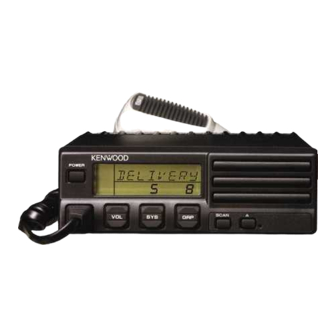
Kenwood TK-930 Interface
The following items are included in the Kenwood TK-930 interface kit:
1. Kenwood TK-930 interface cable assembly.
2. Instruction sheet.
The following steps outline the procedure for interfacing the Kenwood TK-930 radio to the TrakIt-
20.
1. Set the TrakIt-20 up for a bench test and use the AVL Installer program to set the
following operating constants in the installer table to the indicated value:
2. Configure the following jumpers as indicated:
3. Remove top cover from radio.
4. Locate the accessory cable wires (near CN2), cut the following wires and attach them to
locations shown below using wire wrap wire and heat shrink.
5. Replace top radio cover.
6. Connect the DB15 end of the Kenwood TK-930 interface cable to the DB15 connector on
TRAKIT-20.
7. Connect the 15 pin Molex connector to the Kenwood TK-930 radio.
8. Check the Trakit-20 audio levels by performing the alignment procedures described in the
TRAKIT-20 manual.
Transmit indicator active:
Receive indicator active:
PTT output active:
Enable Tx indicator as event 2:
External output active:
External output mode:
JP1
JP4
Green
IC601 pin 1
Red
IC200 pin 7
Yellow
IC200 pin 8
Brown
IC107 pin 2
White/Green
Jct. C123 & R119
Orange
IC107 pin 6 *install 100K resistor
in series with this wire
Low
Low
Low
No
Low
Speaker mute
Removed
A-B
1
Advertisement
Table of Contents

Summary of Contents for Kenwood TK-930
- Page 1 IC107 pin 6 *install 100K resistor in series with this wire 5. Replace top radio cover. 6. Connect the DB15 end of the Kenwood TK-930 interface cable to the DB15 connector on TRAKIT-20. 7. Connect the 15 pin Molex connector to the Kenwood TK-930 radio.
- Page 2 Kenwood TK-930 Interface (cont.) 15 PIN MOLEX DB-15 WHITE YELLOW ORANGE GRAY GREEN BLACK SHIELD BLUE BROWN Kenwood TK-930 Interface Cable Kit 106-KENTK930 Item Description Part No. Qty. HEAT SHRINK TUBE 3/8 199-6099 SCREW/CLIP KIT 231-0014 MOLEX PIN MALE 231-0034...


Need help?
Do you have a question about the TK-930 and is the answer not in the manual?
Questions and answers