
Related Manuals for Ampco Pumps Company QTS-AMPCO


Summary of Contents for Ampco Pumps Company QTS-AMPCO
- Page 1 T w i n S c r e w P u m p Operation and Maintenance Manual QTS-AMPCO w w w . a m p c o p u m p s . c o m Ampco Pumps Company QTS Manual M-030 Rev A 1.16...
-
Page 2: Table Of Contents
Return Policy / Terms & Conditions........Ampco Pumps Company QTS Manual M-030 Rev A 1.16... -
Page 3: About This Manual
Ampco Pumps Company 2045 W Mill Rd. Glendale, WI 53209 414.643.1852 / 800.737.8671 Fax: 414.643.4452 sales@ampcopumps.com The information in this manual may change without notice; we recommend visiting our website for any updates. Ampco Pumps Company QTS Manual M-030 Rev A 1.16... -
Page 4: General Information
Please keep the pump serial number; this will help to order replacement parts and / or make a warranty claim. For more information related to shipping damage and warranty claims please review the General Information or Warranty section in this manual. Ampco Pumps Company QTS Manual M-030 Rev A 1.16... -
Page 5: Safety
• Provide adequate pressure relief devices to prevent excessive pressure on the discharge side of the pump between the pump and the first stop device. • Always follow local safety guidelines. Ampco Pumps Company QTS Manual M-030 Rev A 1.16... -
Page 6: Electrical Connections
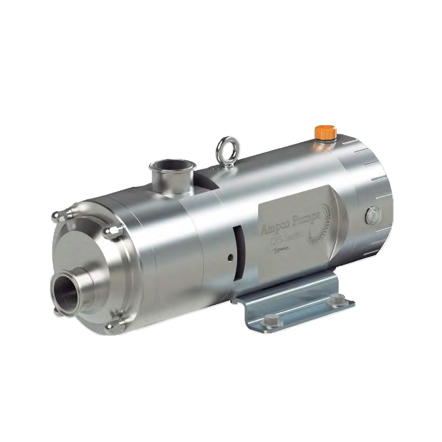
Lifting the Pump Carefully transport the equipment avoiding contact, drops, or damage. To prevent damage, the QTS Series is equipped with an eye bolt located on the gear case for lifting. Ampco Pumps Company QTS Manual M-030 Rev A 1.16... - Page 7 Be sure to place the pump assembly on a stable surface. Once the assembly is in place, check that the screws are properly tightened and that the assembly is aligned; see coupling alignment section in this manual for further instructions. Ampco Pumps Company QTS Manual M-030 Rev A 1.16...
-
Page 8: Know Your Pump
(application) and the CIP process data requirements. This information must match the equipment selection. Be aware that operating your pump under different circumstances can void the warranty. Please keep the data sheet for any clarification. Ampco Pumps Company QTS Manual M-030 Rev A 1.16... - Page 9 Suction port size Tri-Clamp 2" Max. CIP time 30 min Discharge port size Tri-Clamp 2" Max. diff. pressure 50 psi Thermal jacket Piping size 2 in Drive Electric motor with gear reduction Ampco Pumps Company QTS Manual M-030 Rev A 1.16...
-
Page 10: Pump General Assembly
Pump Coupled to a Motor Assembled on a Base. This assembly includes a motor with a coupling, coupling guard, and base. Ampco Pumps Company QTS Manual M-030 Rev A 1.16... -
Page 11: Qts Rotors And Clearances
If you would like to add a variable frequency drive after the analysis of the application, please contact your distributor or Ampco Pumps Company for additional information. Remember that using your pump under different conditions than those explained in the Data Sheet may result in damage to the equipment, injury to personnel and void your warranty. -
Page 12: Pump Operation
If a jacket is used adjust it until the pump temperature drops below 100 ° C/212 ° F. Restart Procedure Before restarting the pump check the smooth rotation of the shafts without restrictions and repeat the startup procedure. Ampco Pumps Company QTS Manual M-030 Rev A 1.16... -
Page 13: Maintenance: Pump Assembly And Disassembly
240 hours Non-continuous operation* 2000 hours Continuous operation** 2500 hours or 4 months (whichever comes first) * Twelve or more pump startups per day ** Less than twelve pump startups per day Ampco Pumps Company QTS Manual M-030 Rev A 1.16... -
Page 14: Bill Of Materials
Coupling set screws 10 lb·ft for all models. Hexagonal bolts/hexagonal nuts motor/base, pump/base, 40 lb·ft. Any other screw 10 lb·ft. Minimum Thickness Gage Model Value 0.007 in 0.007 in 0.010 in Note: Value at both flanks of rotor Ampco Pumps Company QTS Manual M-030 Rev A 1.16... -
Page 15: Exploded View
Exploded View 2X 12K- 2X 12A-J 2X 28 2X 43 6X 38 4X 25 52 4X 2X 15 2X 37 4X 36 2X 26 2X 11 2X 27 33 4X 50 2X 24 2X 23 2X 6X 46 2X 29 22 4X 6X 45 21 4X... - Page 16 Operat ion and Maintenance Manual QTS Series Twin Screw Positive Displacement Pump MAINTENANCE...
-
Page 18: Removing The Rotors
4. Block the rotors with the aid of a wrench using the drive shaft (9) end. Using a six points female socket loosen the rotor nuts (11). First loosen the left side rotor (2) nut torque, then change to the Ampco Pumps Company QTS Manual M-030 Rev A 1.16... -
Page 19: Mechanical Seal Replacement
Now continue with the replacement of the mechanical seals. Mechanical Seal Replacement 1. Here is a description of the procedures for inspection and replacement of the mechanical seals. Every pump has two mechanical seals. Ampco Pumps Company QTS Manual M-030 Rev A 1.16... -
Page 20: Uninstalling The Single Mechanical Seals
Uninstalling the Single Mechanical Seals 1. By hand, remove the stainless steel rotary holder subassembly (12B-F) by grabbing and pulling out from the rotating face (12F). When pulling, the static face (12G) may come along. Ampco Pumps Company QTS Manual M-030 Rev A 1.16... - Page 21 Push with your thumbs from the front of the back cover. Be careful when removing the seal housing to avoid any harsh contact. This step is not necessary if only a seal replacement is required. 8. Repeat these steps to disassemble the other mechanical seal. 12B-F Ampco Pumps Company QTS Manual M-030 Rev A 1.16...
-
Page 22: Installing The Single Mechanical Seals
This step is crucial for the correct assembly of the mechanical seal; failing to do so properly can cause damage to the mechanical seals, the rotors and can even alter the integrity of the pump. DRAG PIN NOTCH Ampco Pumps Company QTS Manual M-030 Rev A 1.16... - Page 23 Place the O-ring (12A) into the front groove. This completes the subassembly of the rotating part of the seal. Ampco Pumps Company QTS Manual M-030 Rev A 1.16...
-
Page 24: Uninstalling The Double Mechanical Seals
5. To remove the seal housing (12L), O-rings (12K and 12N), springs (12M) and the static face of secondary seal (12P) it is necessary to remove the back cover of the pump. Ampco Pumps Company QTS Manual M-030 Rev A 1.16... - Page 25 13. With a hexagonal key, loosen the set screws (12T) from the drive ring (12S) and remove if needed. 14. Repeat these steps to uninstall the rest of the components of the second mechanical seal. Ampco Pumps Company QTS Manual M-030 Rev A 1.16...
-
Page 26: Installing The Double Mechanical Seals
(12G) and two drag pins on the inside for the static face of the secondary mechanical seal (12P). 8. Place O-ring (12K) in the outside groove of the seal housing (12L). 9. Continue placing the springs (12M) inside the seal housing. Ampco Pumps Company QTS Manual M-030 Rev A 1.16... - Page 27 O-ring so there should be no contact between metal and the static face of the primary mechanical seal. Ampco Pumps Company QTS Manual M-030 Rev A 1.16...
- Page 28 (12C) on the inside holes of the holder. 19. Lubricate the inside diameter of the O-ring (12E) and place it on the inside groove of the holder and make sure it is in place. Ampco Pumps Company QTS Manual M-030 Rev A 1.16...
- Page 29 Insert the flush nipples (54), one on each side of the back cover, one works as the inlet and the other as the outlet of the fluid lubricant. 23. At this point you have completed assembly of the double mechanical seals, now continue with the assembly of the rotors. Ampco Pumps Company QTS Manual M-030 Rev A 1.16...
-
Page 30: Rotor Assembly
8. When the rotors reach their end position with the mechanical seals and shafts, tighten the nuts with the torque values according to the pump model. The front faces of the rotors should be aligned. Ampco Pumps Company QTS Manual M-030 Rev A 1.16... - Page 31 13. Secure the front cover with the washers (22) and nuts (21); tighten using a wrench or a six points female socket. Remember to use the corresponding torque values according to the pump model. This concludes the rotor assembly. Ampco Pumps Company QTS Manual M-030 Rev A 1.16...
-
Page 32: Rotor Synchronization
When the keyless shaft hub is tight the gear will rotate with the shaft. 4. Undo the socket head cap screws (46) and remove. All screws have a lock washer (45). Ampco Pumps Company QTS Manual M-030 Rev A 1.16... - Page 33 10. Push the rotors on the shaft until they reach each rotary holder subassembly. Install the rotor nuts (11) and tighten them simultaneously. Avoid contact between rotors. Consult torque specifications for proper settings. Ampco Pumps Company QTS Manual M-030 Rev A 1.16...
- Page 34 14. Tighten the tapered driven ring (20). Tighten the socket head cap screws (46) uniformly, by alternating between them until the maximum torque is reached. View torque table. GAGE GAGE Ampco Pumps Company QTS Manual M-030 Rev A 1.16...
- Page 35 17. Remove the rotors and rotary holder subassemblies. 18. Assemble the gear case cover (10) and fill it with ISO VG-68 oil. 19. Continue to assemble the pump, described in the Seal Assembly and Rotor Assembly section. Ampco Pumps Company QTS Manual M-030 Rev A 1.16...
-
Page 36: Important Notes
14. Every double mechanical seal without exception should be properly lubricated. Even the shortest time operating without lubrication may damage the mechanical seals. The flush system must be installed before starting the pum p. Ampco Pumps Company QTS Manual M-030 Rev A 1.16... - Page 37 18. Use the torque values (according to the pump model) on the components that are indicated. 19. If you have any questions regarding assembly or disassembly, please contact Ampco P u m p s . Ampco Pumps Company QTS Manual M-030 Rev A 1.16...
- Page 38 The following table shows the recommended flow in GPM (LPM) for CIP: Pipe diameter 1.5 m/s 24 (91) 42 (159) 68 (257) 99 (375) 177(670) 410 (1552) Speed 3.0 m/s 48 (121) 84 (318) 136 (295) 198 (749) 354 (1340) 820 (3104) Ampco Pumps Company QTS Manual M-030 Rev A 1.16...
- Page 39 Consideration should also be given to the disposal or recycling of used cleaning liquids and the potential requirement for handling concentrated detergents. Specialists should make the final selection of cleaning detergents/disinfectants. Ampco Pumps Company QTS Manual M-030 Rev A 1.16...
- Page 40 QTS203 - 3.0 m/s 2375 QTS302 - 1.5 m/s 1418 QTS302 - 3.0 m/s 1064 1562 QTS303 - 1.5 m/s 1183 2149 QTS303 - 3.0 m/s 1612 2370 For more information please contact Q-Pumps. Ampco Pumps Company QTS Manual M-030 Rev A 1.16...
- Page 41 Two wrenches are used to tighten one nut against the other so they cannot loosen. To loosen both nuts two wrenches are used turning in the opposite direction. Ampco Pumps Company QTS Manual M-030 Rev A 1.16...
-
Page 42: Return Policy / Terms & Conditions
T E R M S A N D C O N D I T I O N S ENTIRE AGREEMENT. This document contains all of the terms and conditions of the agreement (“the agreement”) between Ampco Pumps Company, Inc. (“Seller”) and the purchaser (“Purchaser”) of the Products (“Products”) to be sold to Purchaser, to the exclusion of any other statements and agreements, and to the exclusion of any terms and conditions incorporated- ted in Purchaser’s order or other documents of Purchaser. - Page 43 In the event performance by Seller under the agreement cannot be accomplished by Seller due to any of the foregoing causes within a reasonable period of time, Seller may, at its option, terminate the agreement Ampco Pumps Company QTS Manual M-030 Rev A 1.16...
- Page 44 Purchaser, Seller has the right to adjust the price to take into account any additional costs caused by an increase or decrease in quantities or in the time required for performance under the agreement. Ampco Pumps Company QTS Manual M-030 Rev A 1.16...
- Page 45 OTHER THEORY OF LIABILITY, AND REGARDLESS OF ANY ADVICE OR REPRESENTA- TIONS (WHETHER OR NOT IN WRITING) THAT MAY HAVE BEEN RENDERED BY SELLER CONCERNING THE DESIGN, MANUFACTURE, SALE, USE OR INSTALLATION OF THE PRODUCTS. Ampco Pumps Company QTS Manual M-030 Rev A 1.16...
- Page 46 Ex-Works (within the meaning of INCOTERMS 2000) and all customs fees, import duties, cargo insurance, taxes and other charges imposed on or relating to the purchase or sale of the Products shall be paid by Purchaser in addition to the stated price. Ampco Pumps Company QTS Manual M-030 Rev A 1.16...
- Page 47 State of Wisconsin, including the Uniform Commercial Code as enacted by such state, without giving effect to its conflict of laws principles. Ampco Pumps Company QTS Manual M-030 Rev A 1.16...
- Page 48 Operation and Maintenance Manual Positive Displacement Pump QTS Series Twin Screw Pump 2045 W. Mill Road Glendale, WI 53209 Phone: 800.737.8671 www.ampcopumps.com...
Need help?
Do you have a question about the QTS-AMPCO and is the answer not in the manual?
Questions and answers