Advertisement
Quick Links
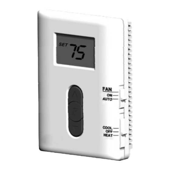
Complete, Easy To Read
INSTALLATION AND OPERATING INSTRUCTIONS
A2203
SYSTEM POWERED, NON-PROGRAMMABLE
DIGITAL HEAT & COOL THERMOSTATS
I M P O R TA N T !
Please read all instructions carefully before beginning installation
and save for future reference. Before removing any wiring from
your existing thermostat, the wires must be labeled with their
terminal designations. Ignore the color of the wires since they
may not comply with any standard.
Thank you for your confidence in our product. You should become fully
acquainted with this thermostat before installing it for usage. Follow the
installation procedures carefully, and one step at a time. This will save you time
and minimize the chance of damaging either the thermostat or the systems that
it controls. These instructions may contain information beyond that required for
your particular installation. Please save these instructions for future reference.
COMPATIBILITY
•The multi-stage A2203 thermostat can be used with most 24 volt, 2 stage heat
and/or 2 stage cool: gas, oil, or electric heating and air conditioning systems,
single-stage heat pump, or single-stage heat pump with Aux heating
systems. .
•These thermostats cannot be used to control gas Millivolt heating systems,
multi-stage heat pumps, or 120/240 volt (line voltage) heating or cooling
systems. Ask your dealer for other thermostats to control those systems.
FEATURES
• Digital, Non-Programmable
• Large, Easy To Read Display
• System Powered Only
with LED Backlight
• Set Temperature Range 45°F to
• F / C Selectable Temperature
95°F
Display
• Clean, Attractive Design
• Fixed 4 Minute Minimum Delay
• Easy To Install
For Compressor Protection
• Gas / Electric Blower Fan Option
INSTALLATION
PLEASE READ ALL INSTRUCTIONS CAREFULLY BEFORE BEGINNING
INSTALLATION.
C A U T I O N
:
This thermostat is protected against normal static electric
discharges. However, in extremely dry weather you should touch
a grounded metal object before touching the thermostat to
minimize the risk of causing damage to the unit.
TOOLS REQUIRED:
• #1 Phillips screwdriver (small - medium)
• Drill with 3/16-in. (4.8mm) drill bit
• Wire stripper/cutter
C A U T I O N :
Turn off electricity to the appliance before
installing or servicing the thermostat or any part
of the system. Do not turn the electricity back on
OFF
until the work is completed.
• Your thermostat is a precision instrument. Please handle it with care.
• Do not short (jumper) across the electric terminals on either the
furnace or air conditioner to test the system. This may damage the
thermostat and void your warranty.
• All wiring must conform to all applicable local codes and ordinances.
• This thermostat should be limited to a maximum of 3 amps; higher
current may cause damage to the thermostat.
THERMOSTAT LOCATION:
On replacement installations, mount the new thermostat in place of the old one
unless the conditions listed below suggest otherwise. On new installations,
follow the guidelines listed below.
1. Locate the thermostat on an inside wall, at about 5 ft. (1.5m) above the floor,
and in a room that is used often.
2. Do not install it where there are unusual heating conditions, such as: direct
sunlight, near a lamp, television, radiator, register, fireplace, on a wall opposite
a stove, or that carries hot water pipes.
3. Do not locate in unusual cooling conditions, such as: on a wall separating an
unheated room, or in a draft from a stairwell, door, or window.
4. Do not locate where air circulation is poor, such as: in a corner or alcove, or
behind an open door.
5. Do not locate in a damp area. This can lead to corrosion that may shorten
thermostat life.
6. Do not install the unit until all construction work and painting has been
completed.
REMOVING THE OLD THERMOSTAT:
1. Switch OFF the electricity to both the furnace and air conditioner; then
proceed with the following:
2. Remove cover from old thermostat. Most are snap-on types and simply pull
off, some have screws on the sides, and these must be loosened first.
3. Take note the letters printed near the wire terminals. Attach labels (enclosed)
to each wire for identification by terminal letter, not color.
4. Make sure the wires do not fall back inside the wall, and remove and label
one wire at a time. Do not allow wires to touch each other or any parts of the
thermostat.
5. Loosen all screws on the old thermostat and/or base, and remove it from the
wall.
C A U T I O N :
Be careful not to drop the body or disturb any
of the electronic parts.
MOUNTING THE NEW THERMOSTAT:
1. Strip insulation leaving 3/8 in. (9.5mm) of bare wire on the ends and clean off
any corrosion present.
2. Fill the wall opening with non-combustible insulation to prevent drafts from
affecting the thermostat while in use.
3. Pull your new thermostat apart by applying pressure to the thumb tab on the
bottom edge of the unit. While pressure is being applied to this release latch,
pull the two halves of the thermostat apart near the bottom edge.
4. Hold the base against the wall. Route the wires through the larger hole
adjacent to the terminal block. Position the base for best appearance (to hide
any marks from an old thermostat). Attach the base to the wall with the four
screws provided.
NOTE: If you are mounting the base to a soft material like plasterboard, or if
you are using the old mounting holes, the screws may not hold. Drill a 3/16-in
(4.8mm) hole at each screw location, and insert the plastic anchors provided.
Then mount the base as described below.
CONNECTING THE WIRES:
5. Clean bare wire ends must be inserted terminal block
and the brass terminal as shown here.
6. Securely tighten all electrical terminal screws
(even unused ones).
WIRING INFORMATION
** Complete heating or cooling system wiring can be found in the WIRE
IDENTIFICATION AND WIRING SCHEMATICS section of this instruction
sheet. The schematics shown provide component information for brand
new installations or for un-referenced wires.
SETUP OPTIONS
A table similar to this one shown below is printed on the thermostat's circuit
board. There may be minor differences present in some of the wording of your
specific model, but the function of each option will be the same.
Jumper
JP1
JP2
JP3
JP4
JP5
JP6
JP7
JP8
JP9
HP-AUX
RC-RH
HEAT
GAS
ELECT
ON
A
Y1
B
O
ONLY
CONCTED
PUMP
HEAT
HEAT
RC-RH
NORMAL
NO FAN
NO B
NO O
OFF
NO A
NO Y1
NORMAL
NO FAN
SEPERATE
Factory
OFF
ON
OFF
ON
OFF
OFF
ON
ON
OFF
Default
JUMPER SETTINGS:
There are ten (10) headers (or jumpers) located inside the thermostat at the
rear of the circuit board. These settings can be changed from their default
values by removing its corresponding black jumper cap and reinstalling the cap
so that it is positioned on the adjacent pair of metal pins. A change to ANY of
the jumper settings will not be recognized until power to the thermostat is
removed, and then power is restored again. This can simply be accomplished
by removing the thermostat from the wired back plate. Each of these jumpers
changes a different setup option. The choices for these options are listed in a
table printed on the circuit board, and are also printed adjacent to each
individual setting jumper.
JP1 - HP-AUX ONLY:
If you have a heat pump with auxiliary heat, and the heat pump is not working,
you can use the auxiliary heat only by moving jumper 1 (heat pump) to jumper
position 1(Aux only).
JP2 - RC-RH CONNECTED OR SEPERATED:
This setting controls whether the HVAC Power is single or RH-RC is separated.
JP3&JP4 - [A] OR [Y1] TERMINAL USAGE OPTION:
This setting determines how the thermostat will use the shared Y1/A terminal
connection on the back plate. Choose the Jumper 3 (A) position to have the
Y1/A terminal powered while in heat mode, and un-powered while in cool and
off modes. Choose the Jumper 4 (Y1) position to have the Y1/A terminal
powered while in cool mode, and un-powered while in heat and off modes.
JP5 - HEAT PUMP OR NORMAL:
This setting determines whether the system is heat-pump or normal.
JP6&JP7 - GAS / ELECTRIC FAN OPERATION:
This setting changes whether the system's blower fan (if applicable) is
controlled by the thermostat in HEAT mode. Choose JP7(ELECT) if you have
electric heating, and require the thermostat to control the fan. Choose JP6(GAS)
if you have a gas heating system, this will allow the furnace itself to control the
operation of the blower fan. In the HEAT PUMP system, you also should choose
JP7(ELECT).
NOTE: If you have an Electric Heat system and the blower does not operate
after installation, locate the "Gas/Electric" option jumper and ensure that it is in
the "Electric" position.
JP8&JP9 - [B] OR [O] TERMINAL USAGE OPTION:
This setting determines how the thermostat will use the shared B/O terminal
connection on the back plate. Choose the Jumper 8 (B) position to have the B/O
terminal powered while in heat mode, and un-powered while in cool and off
modes. Choose the Jumper 9 (O) position to have the B/O terminal powered
while in cool mode, and un-powered while in heat and off modes.
JP10 - FAHRENHEIT OR CELSIUS DISPLAY FORMAT:
This setting controls whether the temperature is shown in degrees
FAHRENHEIT or CELSIUS on the LCD display screen.
COMPLETING THE INSTALLATION
Install your new thermostat onto its base. To do this, start with the bottom tilted
out towards you at first, and line up the two holes in the top of the thermostat
with the two hooks on the top of the back plate. Slowly pivot the bottom of the
thermostat towards the back plate and push firmly on the bottom half of the
thermostat until it is securely latched to the back plate. If the two thermostat
halves do not latch easily, remove and try again. Do not attempt to force them
together.
NOTE: Before use, remove the plastic film (if present) that is
protecting the LCD display screen.
Turn the electrical power back ON to both your heating and/or air conditioning
systems. Verify that both systems (and the blower fan if used) are operating
properly. When set to a high temperature, the heating system should provide
warm air after a short time in Heat Mode. Likewise, a cooling system should
provide cool air after a short time when set to a low temperature in Cool Mode.
JP10
Usually, sound from the furnace and/or air conditioning units can be heard while
Fahrenheit
DISPLAY
either is running. If your system uses a blower fan, the rush of moving air should
Celcious
be heard within a short time after either has been started. Your installation is
DISPLAY
now complete.
ON
FRONT PANEL ITEMS
SYSTEM MODE SWITCH:
The MODE switch has three positions: HEAT, OFF, and COOL. In the winter,
set the mode switch to HEAT to control your heating system; in the summer, set
the switch to COOL to control your air conditioning.
In the spring and fall, or when the windows are open, you can set the switch
OFF.
NOTE: When the system mode switch is in the OFF position, it is normal for the
system's blower fan ("G" terminal if used) to still become activated depending
upon the position of the FAN mode switch (see below).
FAN MODE SWITCH:
The FAN switch has two positions: ON and AUTO.
• In the ON position, the system's blower fan will be commanded ON, and
remain ON while the FAN switch is in the ON position (this also includes when
the System Mode Switch is in the OFF position).
• When the FAN switch is In the AUTO position, the operation of the blower fan
is determined only by the on/off cycling of the heating and cooling systems.
NOTE: The FAN switch only works if your system provides a wire
for the thermostat's "G" terminal.
PUSH BUTTONS:
There are three push buttons in the middle of the unit's display screen. "UP" and
"DOWN" buttons are used to adjust the set point temperature. "F" button is used
to monitor the filter.
FILTER MONITOR
Your thermostat also keeps a record of the number of hours your filter has been
in use. To maximize your system's performance and energy efficiency, change
or clear your filter regularly.
When the total system run time for heat and cool reaches 400 hours, you need
clean or change your system's filter, "FILT" will continue to flash until the
counter is set back to zero.
Under the Filter count screen. Press and hold F for 3 seconds to reset the
FILTER counter. The display will blink, and counters will be cleared to zero.
OPERATING INSTRUCTIONS
TEMPERATURE ADJUSTMENT:
While in HEAT or COOL mode, a single press on either the UP or DOWN button
causes the word "TEMP SET" to appear on the screen. Once "TEMP SET" is
present, the set point temperature can be altered by pressing either the UP or
DOWN button once per degree(FAHRENHEIT) of change.
If there is a large thermal demand present which is greater than the first stage of
heating (W1) or cooling (Y1) can accommodate for, then a second stage of
heating (W2) or cooling (Y2) will be activated.
When the second stage of either heating or cooling becomes active,,the word
"AUX" will be shown on the display screen.
TEMPERATURE LIMIT STOPS:
There are two independent set temperature stops: a Maximum Heat Set
Advertisement

Related Manuals for HaiLin Controls A2203


Summary of Contents for HaiLin Controls A2203
- Page 1 4. Do not locate where air circulation is poor, such as: in a corner or alcove, or •The multi-stage A2203 thermostat can be used with most 24 volt, 2 stage heat changes a different setup option. The choices for these options are listed in a behind an open door.
- Page 2 Temperature, and a Minimum Cool Set Temperature. Each of these WIRING DIAGRAM temperature stops is user adjustable in one-degree (FAHRENHEIT) increments. The heat limit stop prevents the set temperature from being adjusted higher than the heat limit setting. The cool limit stop prevents the set Jumper Figure 4 Jumper Figure 7 Jumper Figure 1...
Need help?
Do you have a question about the A2203 and is the answer not in the manual?
Questions and answers